Table of Contents
Advertisement
Quick Links
Advertisement
Table of Contents

Subscribe to Our Youtube Channel
Related Manuals for ADLINK Technology AMSTX-CF Series


Summary of Contents for ADLINK Technology AMSTX-CF Series
- Page 1 AMSTX-CF Series User’s Manual Embedded Motherboard supporting MXM Graphics Module with 8th/9th Generation Intel® Core™ i7/i5/i3 in LGA1151 Socket Manual Rev.: Revision Date: April 20, 2021 Part Number: 50M-00020-1010 Leading EDGE COMPUTING...
- Page 2 Preface Copyright Copyright © 2020, 2021 ADLINK Technology, Inc. This document contains proprietary information protected by copyright. All rights are reserved. No part of this manual may be reproduced by any mechanical, electronic, or other means in any form without prior written permission of the manufacturer.
- Page 3 AMSTX-CF Series Revision History Revision Description Date Initial release 2020-12-21 Add new models (EGX-MXM-RTX3000 and EGX-MXM-RTX5000); add MXM 2021-04-20 cooler for RTX5000 and 500W power supply; update specifications; update block diagrams; add mating connector list; update DisplayPort BIOS settings Preface...
-
Page 4: Table Of Contents
Table of Contents Preface ..........................ii List of Figures ........................vi List of Tables........................vii Introduction........................1 Packing List ........................1 Available Models......................1 Optional Accessories ....................1 Specifications ......................3 Core System .......................3 I/O Interface ........................3 Video........................... 4 Audio........................... 4 Power Supply......................4 Temperatures ......................4 Humidity........................4 Certificate (EMC) ......................5 Form Factor ........................5 2.10 Operating Systems .....................5... -
Page 5: Preface
AMSTX-CF Series Digital Input/Output Function Library ..............33 DI/O with Windows API.....................33 DisplayPort BIOS Settings..................35 MXM P1000/P2000/T1000/RTX3000/ RTX5000 ............35 MXM P3000/P5000....................35 BIOS Setup.......................37 Menu Structure ......................38 Main ..........................39 Advanced........................42 Chipset........................56 Security........................61 Boot ..........................62 Save & Exit .......................63 Safety Instructions......................64 Getting Service.........................65... -
Page 6: List Of Figures
List of Figures Figure 1: Functional Block Diagram ......................5 Figure 2: IO Panel Connector Locations ....................7 Figure 3: Onboard Connector Locations- Top Side .................8 Figure 4: Onboard Connector Locations - Bottom Side ................9 Figure 5: Mechanical Dimensions - Top View ..................10 Preface... - Page 7 AMSTX-CF Series List of Tables Table 1: IO Panel Connector Definitions ....................7 Table 2: Onboard Connector Definitions - Top Side ................8 Table 3: Onboard Connector Definitions - Bottom Side ................9 Table 4: System Memory Map ......................27 Table 5: IO Map............................. 27 Table 6: IRQ Lines PIC Mode........................
- Page 8 This page intentionally left blank. viii Preface...
-
Page 9: Introduction
ADLINK’s large portfolio of computing products designed in a wide range of form factors. The AMSTX-CF Series Micro-STX motherboard features a socket-type CPU and support for Scalable Graphics Processing Ranging from Pascal to Turing GPUs in a compact form factor. - Page 10 This page intentionally left blank. Introduction...
-
Page 11: Specifications
AMSTX-CF Series Specifications Core System CPU: Desktop 8th/9th Generation Intel® Core™ i7/i5/i3 Processor, LGA1151 socket • Intel® Core™ i7-9700E, 2.6GHz, 12M Cache, 65W TDP, LGA1151, DDR4 2666MHz support (8C/8T) • Intel® Core™ i7-9700TE, 1.8GHz, 12M Cache, 35W TDP, LGA1151, DDR4 2666MHz support (8C/8T) •... -
Page 12: Video
M.2: • Q370 SKU: 1x M.2 E key supporting 1630 or 2230 for Wi-Fi/BT module, 1x M.2 B key supporting 2242 or 2280 for SATA storage module, 1x M.2 M key supporting 2242 or 2280 for SATA/PCIe x4 storage module •... -
Page 13: Certificate (Emc)
AMSTX-CF Series Certificate (EMC) EN55032/35, EN61000-6-2/-4, CE, FCC Part 15B Class B Form Factor 197.72 x 167.32 mm (W x L) ADLINK proprietary mounting hole locations, ADLINK proprietary CPU cooler bracket 2.10 Operating Systems Microsoft® Windows® 10 64-bit Ubuntu 18.04.10 LTS 64-bit 2.11 Functional Block Diagram... - Page 14 This page intentionally left blank. Specifications...
-
Page 15: Mechanical Layout
AMSTX-CF Series Mechanical Layout Connector Locations Figure 2: IO Panel Connector Locations Table 1: IO Panel Connector Definitions Item Description Remarks DisplayPort (from CPU) LAN (I210-AT) RJ453 LAN (I210-AT) CN24 LAN (I219-LM) CN23 2x USB 3.2 Gen1 x1 CN24 2x USB 3.2 Gen1 x1... -
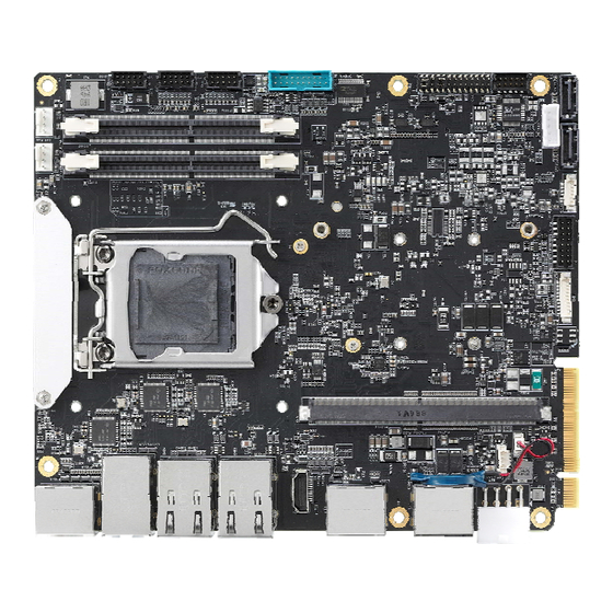
Page 16: Figure 3: Onboard Connector Locations- Top Side
Figure 3: Onboard Connector Locations- Top Side Table 2: Onboard Connector Definitions - Top Side Item Description Item Description CPU socket Panel backlight power and resolution jumper (CN13) DRAM socket for DIMM1 MXM connector (CN5) DRAM socket for DIMM2 PCB edge connector CPU Fan connector RTC battery connector (CN16) System fan connector... -
Page 17: Figure 4: Onboard Connector Locations - Bottom Side
AMSTX-CF Series Figure 4: Onboard Connector Locations - Bottom Side Table 3: Onboard Connector Definitions - Bottom Side Item Description DB40 connector (CN19) M.2_B Key connector (CN17) M.2_M Key connector (CN20) M.2_E Key connector (CN15) LVDS (CN21) Multi-IO voltage selection (SW9) -
Page 18: Mechanical Dimensions
Mechanical Dimensions Dimensions: mm Top View 7.60 12.90 34.93 55.92 77.62 116.87 132.35 147.86 169.80 183.72 197.72 Figure 5: Mechanical Dimensions - Top View Side View Mechanical Layout... -
Page 19: Connector Pinouts
AMSTX-CF Series Connector Pinouts See 3.1 Connector Locations on page 7 for connector locations. LEDs 4.1.1 BMC Status LED and WDT LED 4.1.1.1 Status LED (Blue, LED2) The Status LED is controlled by SEMA. The Status LED will signal system state changes and power up failures including HW-Reset, SW-Reset, Power-Up, Power-Down, Reset-Button and Power-Button activity. -
Page 20: Internal Connectors
Internal Connectors 4.2.1 USB 2.0 Pin Header (CN22) Signal P5V_USB1 P5V_USB2 CN_U2_USB9_N CN_U2_USB14_N CN_U2_USB9_P CN_U2_USB14_P 4.2.2 USB 3.2 Gen1 x1 Pin Header (CN4) Signal Signal P5V_USB56 CN_U3_USB6_T_P CN_U2_USB5_N CN_U3_USB6_T_N CN_U2_USB5_P CN_U3_USB6_R_P CN_U3_USB5_R_N CN_U3_USB6_R_N CN_U3_USB5_R_P CN_U2_USB6_P CN_U3_USB5_T_N CN_U2_USB6_N CN_U3_USB5_T_P P5V_USB56 Note: An adapter cable is available to convert the USB 3.2 signals to USB 2.0. Contact your ADLINK representative for more information. - Page 21 AMSTX-CF Series 4.2.3 PCIe Power Connector Pin Header (CN10) Signal P_+12V_S P_+12V_S P_+5V0_S P_+5V0_S 4.2.4 SATA Power Connector Pin Header (CN14) Signal P_+5V0_S P_+5V0_S P_+5V0_S 4.2.5 COM Pin Headers (CN7) Signal Name RS-232 CC Talk mode DCD# DSR# RS232_RX_ccTalk RTS#...
- Page 22 4.2.6 COM Pin Headers (CN8) Signal Name RS-232 RS-422 RS-485 DCD# Tx/Rx- DSR# Tx/Rx+ N /A RTS# N /A N /A N /A CTS# N /A N /A DTR# N /A N /A N /A N /A 4.2.7 CPU Fan and System Fan Signal FAN_GND P_+12V_FAN...
- Page 23 AMSTX-CF Series 4.2.9 Audio Pin Header (CN9) Signal AUDIO_Sense SPK_RP A_L_IN_L SPK_RN A_L_IN_R GND_AUD A_MIC_IN_L SPK_LP A_MIC_IN_R SPK_LN 4.2.10 Power On Module Connector (CN12) Signal P_+5V0_A P_+3V3_A PWR_BTN# LED_STANDBY RST_BTN# POWER_ON RESET_BUTTON_ALARM# PCH_SATS-L LED_TEMP_ALARM LED_FAN_ALARM P_+12V_A BEEP_TEMP_ALARM Connector Pinouts...
- Page 24 4.2.11 DIO Connector (CN11) Signal 5V_12V_S 4.2.12 12V DC-in Connector (CN3) Signal DCIN DCIN DCIN DCIN 4.2.13 PCB Edge Connector Signal Signal A1 (pin 1 on bottom) B1 (pin 1 at top) P_+12V_S P_+12V_S P_+12V_S P_+12V_S P_+12V_S JTAGE_CLK(NC) PCH_SMB_CLK_A JTAGE_DI(NC) PCH_SMB_DAT_A JTAGE_DO(NC) JTAGE_MS(NC)
- Page 25 AMSTX-CF Series Signal Signal CLKOUT_PCIE_P7 CLKOUT_PCIE_N7 GF_PCIEX5_21_TX_P GF_PCIEX5_21_TX_N GF_PCIEX21_RX_P GF_PCIEX21_RX_N PCH_CLK_REQ7-L GF_PCIEX22_TX_P GF_PCIEX22_TX_N GF_PCIEX22_RX_P GF_PCIEX22_RX_N GF_PCIEX23_TX_P GF_PCIEX23_TX_N GF_PCIEX23_RX_P GF_PCIEX23_RX_N GF_PCIEX24_TX_P GF_PCIEX24_TX_N GF_PCIEX24_RX_P GF_PCIEX24_RX_N PCH_CLK_REQ7-L GF_PCIEX1_TX_P GF_PCIEX1_TX_N GF_PCIEX1_RX_P GF_PCIEX1_RX_N GF_PCIEX2_TX_P GF_PCIEX2_TX_N GF_PCIEX2_RX_P GF_PCIEX2_RX_N GF_PCIEX3_TX_P GF_PCIEX3_TX_N GF_PCIEX3_RX_P GF_PCIEX3_RX_N GF_PCIEX4_TX_P GF_PCIEX4_TX_N GF_PCIEX4_RX_P GF_PCIEX4_RX_N...
- Page 26 4.2.14 DB40 Connector (CN18) Signal Signal VCC_SPI_IN TXD6 RXD6 SPI_BIOS_CS0# FUMD0 SPI_BIOS_CS1# RESET_IN# SPI_BIOS_MISO DATA SPI_BIOS_MOSI SPI_BIOS_CLK OCD0A 3V3_LPC OCD0B PWRBTN# BIOS_DIS0 SYS_RESET# RST# CB_RESET# CLK33_LPC CB_PWROK LPC_FRAME# SUS_S3# LPC_AD3 SUS_S4# LPC_AD2 SUS_S5# LPC_AD1 POSTWDT_DIS# LPC_AD0 SEL_BIOS 3.3V_SMC BIOS_MODE 3.3V_A SMC_STATUS RSVD Connector Pinouts...
- Page 27 AMSTX-CF Series 4.2.15 LVDS Connector (CN21) Signal Signal BLPWR_12V_5V BLPWR_12V_5V LVDS_A2P_1 BLPWR_12V_5V LVDS_A2N_1 BLPWR_12V_5V LVDS_BKLT_CTRL LVDS_A1P_1 LVDS_BKLT_EN LVDS_A1N_1 LVDS_A0P_1 LVDS_A0N_1 LVDS_B3P_1 LVDS_B3N_1 LCD_SEL68_CN LVDS_I2C_CLK_CN LVDS_BCKP_1 LVDS_I2C_DAT_CN LVDS_BCKN_1 PNLPWR_5V_3V PNLPWR_5V_3V LVDS_B2P_1 LVDS_B2N_1 PNLPWR_5V_3V PNLPWR_5V_3V LVDS_B1P_1 LVDS_B1N_1 LVDS_A3P_1 LVDS_A3N_1 LVDS_B0P_1 LVDS_B0N_1 LVDS_ACKP_1...
- Page 28 4.2.16 Onboard Connector Information Internal Connector Cable Connector Manufacturer Part No. Manufacturer Part No. Signal Connector No. JVE, 23N6850-10S10B-01G-B-V9-01, black EVERCONN 2032H-2x5P-3 USB 2.0 Pin Header CN22 (2.0mm pitch) LOTES, ABA-USB-050-K08, blue Shenzhen XINERCHANG Electronic USB 3.2 Gen1 x1 Pin Co.
-
Page 29: Jumper And Switch Settings
AMSTX-CF Series Jumper and Switch Settings 4.3.1 Panel Backlight Power 5V/12 Selection (CN13) Panel Power 12V (default) 4.3.2 Panel Resolution Selection (CN13) Panel Resolution 8-bit (default) 6-bit 4.3.3 Case Open (CN6) Multi-purpose Connector (CN6) Case open 13-14 Function ON Undo (default) 4.3.4... - Page 30 4.3.7 RS-232/CCtalk Selection (CN6) RS-232/CCtalk RS-232 (default) 8-10 CCtalk 9-11 10-12 4.3.8 Data Format and Color Depth Selection (SW1) Data Format and Color Depth 1-4_ON 18bpp 2-3_ON VESA 24bpp 1-4,2-3 OFF JEIDA 24bpp (default) 4.3.9 LVDS Channel Selection (SW2) LVDS Channel 1-4_ON VESA (default) 1-4_OFF...
- Page 31 AMSTX-CF Series 4.3.11 LVDS VDD Selection (SW6) LVDS VDD Selection 1-4_ON, 2-3_OFF 1-4_OFF, 2-3_ON 3.3V (Default) 4.3.12 RI#, 5V, 12V Selection (SW7) RI#, 5V, 12V Selection 1-8_ON, 2-7_OFF,3-6 OFF 1-8_OFF, 2-7_ON,3-6 OFF 1-8_OFF, 2-7_OFF,3-6 ON RI# (default) 4.3.13 DIO Voltage Selection (SW8)
- Page 32 This page intentionally left blank. Connector Pinouts...
-
Page 33: Driver Installation
AMSTX-CF Series Driver Installation Download the drivers for your system from the AMSTX-CF product page at: https://www.adlinktech.com/Products/Industrial_Motherboards_SBCs/MicroSTX_Motherboard/AMSTX-CF_Series Driver Installation... - Page 34 This page intentionally left blank. Driver Installation...
-
Page 35: System Resources
AMSTX-CF Series System Resources System Memory Map Table 4: System Memory Map Address Range (Decimal) Address Range (Hex) Size Description (4GB – 2MB) FFE00000 – FFFFFFFF 2 MB High BIOS Area (4GB – 18MB) – (4GB –17MB – 1) FEE00000 – FEEFFFFF... -
Page 36: Interrupt Request (Irq) Lines
Interrupt Request (IRQ) Lines 6.3.1 IRQ Lines PIC Mode Table 6: IRQ Lines PIC Mode Note: Table lists IRQ lines mapping when APIC mode is disabled. IRQ # Typical Interrupt Resource Connected to Pin Available Counter 0 Keyboard Controller Cascade Interrupt from slave PIC Serial Port 2 (COM2) IRQ3 via SERIRQ/PIRQ Note... - Page 37 AMSTX-CF Series IRQ # Typical Interrupt Resource Connected to Pin Available IRQ11 via SERIRQ/PIRQ IRQ12 via SERIRQ/PIRQ Math Processor Generic 16-511 Microsoft ACPI-Compliant System System Resources...
-
Page 38: Pci/Pcie Device
PCI/PCIe Device 6.4.1 PCI Configuration Space Map Table 8 PCI Configuration Space Map NOTE: The bus number changes when the PEG/PCIe port has a bridge device connected. Device Function Routing Description Number Number Number 0x00 Intel HOST Bridge - 6 Cores/Desktop 0x02 Internal IGFX - GT2/6 or 8 Cores/Desktop... -
Page 39: Smbus Slave Addresses
AMSTX-CF Series 6.4.2 PCI Interrupt Routing Map Table 9 PCI Interrupt Routing Map Audio xHCI SATA SMBus Line Controller Controller Controller #1 Controller Controller Controller Int0 INTA: 16 INTA: 16 INTA: 16 INTA: 16 INTA: 16 INTA: 16 Int1 INTB: 17... - Page 40 This page intentionally left blank. System Resources...
-
Page 41: Digital Input/Output Function Library
AMSTX-CF DI/O API library files and a demo program (including source code) can be downloaded from https://www.adlinktech.com/Products/Industrial_Motherboards_SBCs/MicroSTX_Motherboard/AMSTX-CF_Series To use the DI/O function library for the AMSTX-CF series, include the GpioLib.h header file and GpioLib.lib linkage library in the C++ project. DI/O functions are as follows. - Page 42 RegisterInterruptEvent This API is used to register the event when there is a change in the state of a digital input pin. char RegisterInterruptEvent(HANDLE Event, UCHAR Pin) Argument: Event: Handle of the event waiting for interrupt notification. Pin: The number of an input pin. Return value: GPIO_OK on success.
-
Page 43: Displayport Bios Settings
AMSTX-CF Series DisplayPort BIOS Settings MXM P1000/P2000/T1000/RTX3000/ RTX5000 BIOS Setting DisplayPort Primary Internal LVDS Post Stage Windows 10 Display Graphics DP port DP port DP port DP port from CPU from MXM from CPU from MXM IGFX Enable Enable Enable... - Page 44 BIOS Setting DisplayPort Primary Internal LVDS Post Stage Windows 10 Display Graphics DP port DP port DP port DP port from CPU from MXM from CPU from MXM Auto Enable Auto Auto Enable IGFX Enable Disable Enable Disable Auto Enable Disable IGFX Disable...
-
Page 45: Bios Setup
AMSTX-CF Series. The BIOS setup program includes menus for configuring settings and enabling features of the AMSTX-CF Series. Most users do not need to use the BIOS setup program, as the AMSTX-CF Series ships with default settings that work well for most configurations. -
Page 46: Menu Structure
9.1 Menu Structure This section presents the six primary menus of the BIOS Setup Utility. Use the following table as a quick reference for the contents of the BIOS Setup Utility. The subsections in this section describe the submenus and setting options for each menu item. -
Page 47: Main
AMSTX-CF Series 9.2 Main The Main Menu provides read-only information about your system and also allows you to set the System Date and Time. Refer to the tables below for details of the submenus and settings. 9.2.1 Main > BIOS Information... - Page 48 9.2.5 Main > PCH Information Feature Options Description PCH SKU Info only PCH SKU Stepping Info only PCH Stepping 9.2.6 Main > Board Information > Board Information Feature Options Description Board Information Info only Serial Number Info only Serial Number Manufacturing Date Info only Manufacturing Date...
- Page 49 AMSTX-CF Series 9.2.9 Main > Access level Feature Options Description Access Level Administrator / User BIOS Setup...
-
Page 50: Advanced
9.3 Advanced This menu contains the settings for most of the user interfaces in the system. 9.3.1 Advanced > CPU Configuration Feature Options Description CPU Configuration Info only Type Info only Displays the Processor Type Package Info only Displays the Processor Package Stepping Info only Displays the Processor Stepping. - Page 51 AMSTX-CF Series Feature Options Description C states Disabled Enable/Disable CPU Power Management. Allows CPU to go to C states when it's not 100% utilized. Enabled C-State Auto Demotion Disabled Configure C-State Auto Demotion C1 and C3 C-State Un-demotion Disabled Configure C-State Un-demotion...
- Page 52 Feature Options Description 1920x1200 1440x900 1600x900 1024x768 1280x800 1920x1080 2048x1536 Spreading depth Clock frequency center spreading depth. No Spreading 0.5% 1.0% 1.5% 2.0% 2.5% Data format and Color Depth Data format and Color Depth select VESA 24 bpp JEIDA 24 bpp JEIDA/vesa 18 bpp LVDS Output Mode Single/Dual mode select...
- Page 53 AMSTX-CF Series Feature Options Description Restore AC Power Loss Power On Select AC power state when power is re-applied after a power failure. Power Off Last State Power Supply Unit Emulate AT Mode ATX: OS will turn off system power when shutdown.
- Page 54 9.3.6 Advanced > System Management > SEMA Features Feature Options Description SEMA Features Info only Uptime & Power Cycles Counter Info only Uptime & Power Cycles Counter System Restart Event Info only System Restart Event 1024 Bytes User-Flash Info only 1024 Bytes User-Flash Watchdog Info only...
- Page 55 AMSTX-CF Series 9.3.7 Advanced > System Management > Flags Feature Options Description Flags Info only BMC Flags Info only BMC Flags BIOS Select Info only BIOS Select ATX/AT-Mode Info only ATX/AT-Mode Exception Code Info only Exception Code 9.3.8 Advanced > System Management > SPI ROM WP...
- Page 56 Feature Options Description Info only GPU Temperatures Current Info only Current of GPU temperature Startup Info only Startup of GPU temperature Info only Min of GPU temperature Info only Max of GPU temperature CPU Fan Speed Info only CPU Fan Speed System Fan Speed Info only System Fan Speed...
- Page 57 AMSTX-CF Series Feature Options Description Trigger Temperature 0-100 Trigger Temperature Default: 85 PWM Level 0-100 PWM Level Default: 80 Trigger Point 4 Info only Trigger Temperature 0-100 Trigger Temperature Default: 92 PWM Level 0-100 PWM Level Default: 100 System Smart FanTemperature Source...
- Page 58 Feature Options Description PWM Level 0-100 PWM Level Default: 25 Trigger Point 2 Info only Trigger Temperature 0-100 Trigger Temperature Default: 45 PWM Level 0-100 PWM Level Default: 50 Trigger Point 3 Info only Trigger Temperature 0-100 Trigger Temperature Default: 60 PWM Level 0-100 PWM Level...
- Page 59 AMSTX-CF Series Feature Options Description COM1 Control Select COM1 mode. RS232 only RS232 Ring1 Wake Disabled Disable/Enable RI ping for Wake On Ring function(PCH PME# signal) Enabled COM2 Device Settings Info only IO=2F8; IRQ=3; COM2 Control Select COM2 mode. RS232, RS422 or RS485...
- Page 60 Feature Options Description Data Bits Data Bits. Parity A parity bit can be sent with the data bits to detect None some transmission errors. Even: parity bit is 0 if the Even num of 1's in the data bits is even. Odd: parity bit is 0 if num of 1's in the data bits is odd.
- Page 61 AMSTX-CF Series Feature Options Description Info only Available PCR banks Disabled Enable or Disable SHA-1 PCR Bank SHA-1 PCR Bank Enabled Disabled Enable or Disable SHA256 PCR Bank SHA256 PCR Bank Enabled Schedule an Operation for the Security Device. Pending operation...
- Page 62 9.3.18 Advanced > NVMe Configuration Feature Options Description Info only NVMe Configuration Info only List NVMe Device 9.3.19 Advanced > Network Stack Configuration Feature Options Description Enable/Disable UEFI Network Stack Network Stack Disable Enable Enable/Disable IPv4 PXE boot support. If disabled, Ipv4 PXE Support Disable IPv4 PXE boot support will not be available.
- Page 63 AMSTX-CF Series 9.3.22 Advanced > RAM Disk Configuration > Create raw Feature Options Description Number The valid RAM disk size should be multiples of the Size (Hex): RAM disk block size. Create a new RAM disk with the given starting and Create &...
-
Page 64: Chipset
9.4 Chipset 9.4.1 Chipset > System Agent (SA) Configuration Feature Options Description Info only System Agent (SA) Configuration Info only SA PCIe Code Version SA PCIe Code Version Info only Supported or not VT-d Sub-Menu Memory Configuration Parameters Memory Configuration ► Sub-Menu Graphics Configuration Graphics Configuration ►... - Page 65 AMSTX-CF Series 9.4.3 Chipset > System Agent (SA) Configuration > Graphics Configuration Feature Options Description Info only Graphics Configuration 14-31 Graphics turbo IMON current values supported (14- Graphics Turbo IMON Current Default: 31 Auto Select which of IGFX/PEG Graphics device should Primary Display be Primary Display.
- Page 66 Feature Options Description Sub-Menu HD Audio Subsystem Configuration Settings HD Audio Configuration ► Disable/Enable PCH digital I/O device PCH digital I/O device Disabled Enabled Enable/Disable setting SPD Write Disable. For SPD Write Disable TRUE security recommendations, SPD write disable bit FALSE must be set.
- Page 67 AMSTX-CF Series Feature Options Description Info only SATA device info Serial ATA Port 3 Info only SATA device info Serial ATA Port 4 9.4.8 Chipset > PCH-IO Configuration > USB Configuration Feature Options Description Info only USB Configuration Select 'Disabled' for pin-based debug. If pin-based...
- Page 68 Feature Options Description Disabled U2_USB9_P (INTERNAL USB) Enabled Disabled U2_USB14_P (INTERNAL USB) Enabled 9.4.9 Chipset > PCH-IO Configuration > Security Configuration Feature Options Description Info only Security Configuration Enable/Disable the PCH BIOS Lock Enable feature. BIOS Lock Disabled Required to be enabled to ensure SMM protection of Enabled flash.
-
Page 69: Security
AMSTX-CF Series 9.5 Security 9.5.1 Security > Password Description Feature Options Description Password Description Info only Administrator Password Enter password Set Administrator Password User Password Enter password Set User Password Secure Boot menu ► Submenu Secure Boot configuration 9.5.2 Security > Secure Boot menu... -
Page 70: Boot
9.6 Boot 9.6.1 Boot > Boot Configuration Feature Options Description Boot Configuration Info only Setup Prompt Timeout Number of seconds to wait for setup activation key. 65535 (0xFFFF ) means indefinite waiting. Bootup NumLock State Select the keyboard NumLock state. Quiet Boot Disabled Enable or disables Quiet Boot option. -
Page 71: Save & Exit
AMSTX-CF Series 9.7 Save & Exit Feature Options Description Save Changes and Exit Yes No Exit system setup after saving the changes. Discard Changes and Exit Yes No Exit system setup without saving any changes. Save Changes and Reset Yes No Reset the system after saving the changes. -
Page 72: Safety Instructions
Safety Instructions Read and follow all instructions marked on the product and in the documentation before you operate your system. Retain all safety and operating instructions for future use. • Please read these safety instructions carefully. • Please keep this User‘s Manual for later reference. •... -
Page 73: Getting Service
5215 Hellyer Avenue, #110, San Jose, CA 95138, USA Tel: +1-408-360-0200 Toll Free: +1-800-966-5200 (USA only) Fax: +1-408-360-0222 Email: info@adlinktech.com ADLINK Technology (China) Co., Ltd. Address: 300 Fang Chun Rd., Zhangjiang Hi-Tech Park, Pudong New Area Shanghai, 201203 China Tel: +86-21-5132-8988 Fax: +86-21-5132-3588 Email: market@adlinktech.com...
Need help?
Do you have a question about the AMSTX-CF Series and is the answer not in the manual?
Questions and answers