Table of Contents
Advertisement
Quick Links
Advertisement
Table of Contents

Related Manuals for ADLINK Technology NuDAQ ACL-8216


Summary of Contents for ADLINK Technology NuDAQ ACL-8216
- Page 1 ® N u D A Q ACL-8216 16-bit High Resolution Data Acquisition Card User’s Guide...
- Page 2 Trademarks NuDAQ, ACL-8216 are registered trademarks of ADLINK Technology Inc., Other product names mentioned herein are used for identification purposes only and may be trademarks and/or registered trademarks...
-
Page 4: Table Of Contents
Table of Contents How to Use This Guide ..........iii Chapter 1 Introduction ..........1 Features................2 Specifications..............2 Software Support..............4 Chapter 2 Installation ..........5 What You Have ..............5 Unpacking................5 ACL-8216's Layout............... 6 Jumper and DIP Switch Description ........8 Base Address Setting............ - Page 5 Digital Input and Output............ 33 Timer/Counter Operation..........33 Chapter 5 C/C++ Library..........39 Installation................ 39 _8216_Initial..............40 _8216_Switch_Card_No............. 41 _8216_DI................42 _8216_DI _Channel............42 _8216_DO ................43 _8216_DA ................44 _8216_AD_Input_Mode ............46 _8216_AD_Set_Channel ............ 47 5.10 _8216_AD_Set_Range ............49 5.11 _8216_AD_Set_Mode ............50 5.12 _8216_AD_Soft_Trig ............
-
Page 6: How To Use This Guide
H o w t o U s e T h i s G u i d e This manual is designed to help you use the ACL-8216. The manual describes how to modify various settings on the ACL-8216 card to meet your requirements. -
Page 8: Chapter 1 Introduction
I n t r o d u c t i o n The ACL-8216 is a high performance, high resolution multi -function data acquisition card for the IBM PC or compatible computers. Introduction • 1... -
Page 9: Features
The ACL-8216 series is designed to combine all the data acquisition functions, such as A/D, D/A, DIO, and timer/counter in a single board, The high-end specifications of the card makes it ideal for wide range of applications requiring high resolution 16-bit data acquisition at low cost. - Page 10 • Number of channels: 16 single-ended or 8 differential • Input Range: (programmable) Bipolar : ± 10V, ± 5V, ± 2.5V, ± 1.25V • Conversion Time: 8 µ sec • Sampling Rate: 100KHz maximum for single channe 20KHz maximum for multi-channels multiplexing •...
-
Page 11: Software Support
• A/D pacer: 32-bit timer( two 16-bit counter cascaded together) with a 2MHz clock base • Counter: One 16-bit counter with an internal 2MHz clock base or external clock • Pacer Output: 0.00046 Hz ~ 100K Hz ♦ General Specifications •... -
Page 12: Chapter 2 Installation
I n s t a l l a t i o n This chapter describes how to install the ACL-8216. At first, the contents in the package and unpacking information that you should care about are described. The jumpers and switches setting for the ACL-8216's base address, analog input channel configuration, interrupt IRQ level, voltage source, etc. -
Page 13: Acl-8216'S Layout
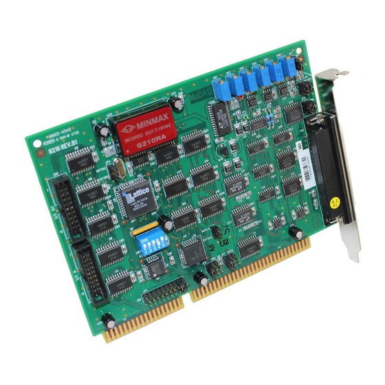
Inspect the card module carton for obvious damage. Shipping and handling may cause damage to your module. Be sure there are no shipping and handing damages on the module before processing. After opening the card module carton, extract the system module and place it only on a grounded anti-static surface component side up. - Page 14 Figure 2.1 PCB Layout of the ACL-8216 Installation • 7...
-
Page 15: Jumper And Dip Switch Description
Jumper and DIP Switch Description You can change the ACL-8216's channels and the base address by setting jumpers and DIP switches on the card. The card's jumpers and switches are preset at the factory. You can change the jumper settings for your own applications. A jumper switch is closed (sometimes referred to as "shorted") with the plastic cap inserted over two pins of the jumper. - Page 16 I/O port Address(Hex) 200-20F 210-21F 220-22F (default) 230-23F 300-30F 3F0-3FF Table 2.2 Possible Base Address Combinations A0, ..., A9 is corresponding to PC Bus address lines A9 is always set as “1”. How to define the base address for the ACL-8216 ? The DIP1 to DIP6 in the switch SW1 are one to one corresponding to the PC bus address line A8 to A4.
- Page 17 10 • Installation...
-
Page 18: Analog Input Channel Configuration
Analog Input Channel Configuration The ACL-8216 offer 16 single-ended or 8 differential analog input channels. The jumper JP3 controls the analog input channel configuration. The settings of JP3 is specified as following illustration. SINGLE Single-ended (default setting) DIFF SINGLE Differential Input DIFF Figure 2.3 Analog Input Channels Configuration DMA Channel Setting... -
Page 19: Internal/External Trigger Setting
DACK NO DMA DACK DMA 1 (Default) DACK DMA 3 Figure 2.4 DMA Channel Setting Internal/External Trigger Setting The A/D conversion trigger source of ACL-8216 comes from internal or external. The internal or external trigger source is setting by JP4, as shown on Figure 2.5. -
Page 20: Clock Source Setting
Internal INTTRG (default setting) EXTT INTTRG External Trigger EXTT Figure 2.5 Trigger Source Setting Internal Clock INTCLK Source : 2MHz (default setting) EXTCLK External Clock INTCLK Source EXTCLK Figure 2.6 Timer's Clock Source Setting Clock Source Setting The 8254 programmable interval timer is used in the ACL-8216. It provides 3 independent channels of 16-bit programmable down counters. -
Page 21: Irq Level Setting
2.10 IRQ Level Setting The ACL-8216 can connect to any one of the interrupt lines of the PC I/O channel. The interrupt line is selected by the jumper JP7. If you wish to use the interrupt capability of ACL-8216, you must select an interrupt level and place the jumper in the appropriate position to enable the particular interrupt line. - Page 22 J P 2 D / A C H 1 i s E x t e r n a l I N T R E F I N T R E F D / A C H 2 i s E x t e r n a l E x t R e f 1 E x t R e f 2 J P 2...
-
Page 23: Connectors Pin Assignment
2.12 Connectors Pin Assignment The ACL-8216 comes equipped with two 20-pin insulation displacement connectors - CN1 and CN2 and one 37-pin D-type connector - CN3. The CN1 and CN2 are located on board and CN3 located at the rear plate. CN1 is used for digital signal output, CN2 for digital signal input, CN3 for analog input, analog output and timer/counter's signals. - Page 24 GND : Digital ground • CN 3: Analog Input/Output & Counter/Timer ( for single-ended connection) AI10 AI11 AI12 AI13 AI14 AI15 A.GND A.GND A.GND A.GND V.REF ExtRef2 ExtRef1 +12V A.GND GATE0 D.GND GATE COUT0 ExtTrg ExtCLK Figure 3.3a. Pin Assignment of CN3 •...
-
Page 25: Daughter Board Connection
Figure 3.3b. Pin Assignment of CN3 Legend: AIn : Analog Input Channel n ( single-ended) AIHn : Analog High Input Channel n ( differential) AILn : Analog Low Input Channel n ( differential) ExtRef n : External Reference Voltage for D/A CH n AOn : Analog Output Channel n ExtCLK : External Clock Input ExtTrig : External Trigger Signal... - Page 26 advantage of board is an 500Vdc isolation voltage is provided, and it can protect your PC system from damage when an abnormal input signal is occurred. 2.13.4 Connect with ACLD-9185 The ACLD-9185 is a 16 channel SPDT relay output board. This board is connected with CN2 of ACL-8216 via 20-pin flat cable.
-
Page 28: Chapter 3 Registers Format
R e g i s t e r s F o r m a t The detailed descriptions of the register format and structure of the ACL-8216 are specified in this chapter. This information is quite useful for the programmer who wish to handle the card by low-level program. -
Page 29: A/D Data Registers & Status Control Register
Base + 11 Not Used Mode Control Base + 12 Not Used Software A/D trigger Base + 13 Not Used DO low byte Base + 14 Not Used DO high byte Base + 15 Not Used Not Used Table 3.1 I/O Address A/D Data Registers &... -
Page 30: A/D Channel Multiplexer Register
-Full Scale -10V 1000 0000 0000 0000 8000 Table 3.2 Ideal Input Voltage and Output Code Address : BASE +8 Attribute: read only Data Format: BASE+8 DRDY DRDY: Data Ready Signal. 1: A/D data is not ready 0: A/D conversion is completed. It will be set to 1, when reading the low byte. -
Page 31: A/D Range Control Register
S.E. CH0 S.E. CH1 S.E. CH2 S.E. CH3 S.E. CH4 S.E. CH5 S.E. CH6 S.E. CH7 S.E. CH8 S.E. CH9 S.E. CH10 S.E. CH11 S.E. CH12 S.E. CH13 S.E. CH14 S.E. CH15 D.I. CH0 D.I. CH1 D.I. CH2 D.I. CH3 D.I. -
Page 32: A/D Operation Mode Control Register
Data Format: BASE+9 GAIN Mode Input Range ±10V Bipolar ±5V Bipolar ±2.5V Bipolar ±1.25V Bipolar A/D Operation Mode Control Register The A/D operation includes the analog signal conversion and the data transformation. This register controls the internal trigger mode and data transformation method. It is initialized as software trigger and program polling transfer when your PC is reset or power on. -
Page 33: Clear Interrupt Register
3. As long as not the DMA mode is not used, the program polling is alwayse possible. The syncronization of A/D conversion and data transfer should be concerned when use program polling. 4. The interrupt will be occurred after end of conversion if the "timer pacer trigger and interrupt transfer"... - Page 34 are provided by the ACL-8216. The address Base + 6 and Base + 7 are used for digital input channels, and the address Base + 13 and Base + 14 are used for digital output channels. Address : BASE + 6 & BASE + 7 Attribute: read only Data Format: Base + 6...
-
Page 35: D/A Output Register
D/A Output Register The D/A converter will convert the D/A output register data to the analog signal. The register data of the address Base + 4 and Base + 5 are used for D/A channel 1, Base +6 and Base +7 are used for D/A channel 2. -
Page 36: Chapter 4 Operation Theorem
Base + 1 Counter 1 Register ( R/W) Base + 2 Counter 2 Register ( R/W) Base + 3 8254 CONTROL BYTE O p e r a t i o n T h e o r e m The operation theorem of the functions on ACL-8216 card is described in this chapter. - Page 37 can read the converted data from the A/D data registers. Please refer section 4.2 for the A/D data format. The A/D data should be transferred into PC's memory for further using. The ACL-8216 provides three data transfer modes that allow users to optimize the DAS system.
- Page 38 modes, because the users can handle the external signal by outside device. The external trigger can combine with the DMA transfer, interrupt data transfer, or even program polling data transfer. Generally, the interrupt data transfer is often used when external trigger mode is used.
-
Page 39: D/A Conversion
directly between the ACL-8216 and the PC’s memory at the fastest possible rate, without using any CPU time. The A/D data is automatically transferred to PC's memory after conversion completed. The DMA transfer mode is very complex to program. It is recommended to use the high level program library to operate this card. -
Page 40: Digital Input And Output
D/A reference voltage which set by the JP1,JP2 and JP3. Please refer section 2.11 for jumper setting. The reference voltage will effect the output voltage. If the reference voltage is -5V, the D/A output scaling will be 0~5V. If the reference voltage is -10V, the D/A output scaling will be 0~10V. - Page 41 The ACL-8216 has an interval timer/counter 8254 on board. It offers 3 independent 16-bit programmable down counters; counter 1 and counter 2 are cascaded together for A/D timer pacer trigger of A/D conversion. and counter 0 is free for your applications. The following figure shows the 8254 timer/counter connection.
- Page 42 • motor control For more information about the 8254 , please refer to the NEC Microprocessors and peripherals or Intel Microsystems Components Handbook. Pacer Trigger Source The counter 1 and counter 2 are cascaded together to generate the timer pacer trigger of A/D conversion. The frequency of the pacer trigger is software controllable.
- Page 43 • SC1 & SC0 - Select Counter ( Bit7 & Bit 6) COUNTER Select Counter 0 Select Counter 1 Select Counter 2 ILLEGAL • RL1 & RL0 - Select Read/Load operation ( Bit 5 & Bit 4) OPERATION COUNTER LATCH FOR STABLE READ READ/LOAD LSB ONLY READ/LOAD MSB ONLY READ/LOAD LSB FIRST, THEN MSB...
- Page 44 • Mode 3: Square Wave Rate Generator. • Mode 4: Software Triggered Strobe. • Mode 5: Hardware Triggered Strobe. All detailed description of these six modes are written in Intel Microsystems Components Handbook Volume II Peripherals. Registers Format • 37...
-
Page 46: Chapter 5 C/C++ Library
C / C + + L i b r a r y This chapter describes the DOS software library, which is free supplied. The DOS library software includes a utility program, C language library, and some demonstration programs, which can help you reduce the programming work. -
Page 47: 8216_Initial
_8216_Initial @ Description An ACL-8216 card is initialized according to the card number and the corresponding base address. Every ACL-8216 Multi-Function Data Acquisition Card have to be initialized by this function before calling other functions. @ Syntax int _8216_Initial(int card_number, int base_addresss ) @ Argument card_number: The card number to be initialized, only... -
Page 48: 8216_Switch_Card_No
_8216_Switch_Card_No @ Description This function is used on dual-cards system. After initialized two ACL- 8216 cards, this function is u sed to select which card is used currently. Note: In this library, only two ACL-8216 can be initialized. The reason is only two DMA channels are supported in the card. -
Page 49: Di _Channel
_8216_DI @ Description This function is used to read data from digital input port. There are 16 bits of digital input on the ACL-8216. The bit 0 to bit 7 are defined as low byte and the bit 8 to bit 15 are defined as the high byte. @ Syntax int _8216_DI( int port_number, unsigned char *data ) @ Argument... - Page 50 @ Example #include "8216.h" main() unsigned int data; _8216_Initial( CARD_1, 0x220 ); /* Assume NoError when Initialize ACL-8216 */ for( ch=0; ch<16; ch++ ) _8216_DI_channel( ch , &data ); printf( "The value if DI channel %d is %d.\n" , ch , data ); _8216_DO @ Description This function is used to write data to digital output ports.
- Page 51 /* Assume NoError when Initialize ACL-8216 */ _8216_DO( DO_LO_BYTE , 0x55 ); printf( "The low byte is now 0x55.\n" ); _8216_DO( DO_HI_BYTE , 0xAA ); printf( "The high byte is now 0xAA.\n" ); A more detailed example program is provided. ('DO_DEMO.C') _8216_DA @ Description...
- Page 52 printf( "The output voltage of CH1 is 2.5V.\n" ); _8216_DA( CH_2 , 0xFFF ); printf( " The output voltage of CH2 is 5V.\n" ); A more detailed example program is provided. ('DA_DEMO.C') C/C++ Library • 45...
-
Page 53: 8216_Ad_Input_Mode
_8216_AD_Input_Mode @ Description This function is only useful for ACL-8216 ver. B series.This function is used to set A/D input mode to single-ended or differential mode. The default mode of A/D input is single-ended, so the A/D channel number can be set between 0 to 1 5. If the A/D mode is set as differential, the input channel can be selected from channel 0 to 7 only. -
Page 54: 8216_Ad_Set_Channel
printf( " AD channel 3 is now selected.\n" ); … /* the following A/D’s operation is based on channel 3 */ _8216_AD_Set_Channel @ Description This function is used to set AD channel by means of writing data to the channel multiplexer register. There are 16 single-ended A/D channels in ACL-8216, so the channel number should be set between 0 to 15 only. - Page 55 48 • C/C++ Library...
-
Page 56: 8216_Ad_Set_Range
5.10 _8216_AD_Set_Range @ Description This function is used to set the A/D range by means of writing data to the A/D range control register. There are two factors will change the analog input range- Gain and Input type. The Gain can be choice from 1,2,4 and 8. -
Page 57: 8216_Ad_Set_Mode
5.11 _8216_AD_Set_Mode @ Description This function is used to set the A/D trigger and data transfer mode by means of writing data to the mode control register. The hardware initial state of the ACL-8216 is set as AD_MODE_1 software( internal) trigger with program polling data. - Page 58 C/C++ Library • 51...
-
Page 59: 8216_Ad_Soft_Trig
5.12 _8216_AD_Soft_Trig @ Description This function is used to trigger the A/D conversion by software. When the function is called, a trigger pulse will be generated and the converted data will be stored in the base address Base +4 and Base @ Syntax int _8216_AD_Soft_Trig( void ) @ Argument... -
Page 60: 8216_Ad_Acquire
5.13 _8216_AD_Acquire @ Description This function will set the A/D mode as AD_MODE_1 (Software trigger, Software polling), generate a software trigger to begin A/D conversion, then poll the A/D conversion data. It reads the 16-bit A/D data until the data is ready ('data ready' bit becomes low). @ Syntax int _8216_AD_Aquire( int *ad_data ) @ Argument... -
Page 61: 8216_Clr_Irq
5.14 _8216_CLR_IRQ @ Description This function is used to clear interrupt request which requested by the ACL-8216. If you use interrupt to transfer A/D converted data, you should use this function to clear interrupt request status, otherwise no new coming interrupt will be generated. @ Syntax int _8216_CLR_IRQ( void ) @ Argument... - Page 62 int count , int *ad_buffer unsigned int c1, unsigned int c2) C/C++ Library • 55...
- Page 63 @ Argument ad_ch_no: A/D channel number ad_gain: A/D range value Input Range (V) Gain Range Code ±10 V ±5 V ±2.5 V ±1.25 V dma_ch_no: DMA channel number, DMA_CH_1 or DMA_CH_3. This should be the same as the setting of JP8 and JP9 on hardware. irq_ch_no: IRQ channel number, used to stop DMA.
-
Page 64: 8216_Ad_Dma_Status
5.16 _8216_AD_DMA_Status @ Description Since the _8216_AD_DMA_Start function is executed in background, you can issue the function _8216_AD_DMA_Status to check its operation status. @ Syntax int _8216_AD_DMA_Status( int *status , int *count ) @ Argument status: status of the DMA data transfer 0: AD DMA is not completed 1: AD DMA is completed count:... - Page 65 58 • C/C++ Library...
-
Page 66: 8216_Ad_Int_Start
5.18 _8216_AD_INT_Start @ Description The function will perform A/D conversion N times with interrupt data transfer by using pacer trigger. It takes place in the background which will not stop until the N-th conversion has completed or your program execute _8216_AD_INT_Stop() function to stop the process. After executing this function, it is necessary to check the status of the operation by using the function 8216_AD_INT_Status(). -
Page 67: 8216_Ad_Int_Status
5.19 _8216_AD_INT_Status @ Description Since the _8216_AD_INT_Start() function is executed in background, you can issue the function _8216_AD_INT_Status to check the status of interrupt operation. @ Syntax int _8216_AD_INT_Status( int *status , int *count ) @ Argument status: status of the INT data transfer 0: A/D INT is completed 1: A/D INT is not completed count:... -
Page 68: 8216_Ad_Timer
5.21 _8216_AD_Timer @ Description This function is used to setup the Timer #1 and Timer #2. Timer #1 & #2 are used as frequency divider for generating constant A/D sampling rate dedicatedly. It is possible to stop the pacer trigger by setting any one of the dividers as 0. -
Page 69: 8216_Timer_Start
5.22 _8216_Timer_Start @ Description The Timer #0 on the ACL-8216 can be freely programmed by the users. This function is used to program the Timer #0. This timer can be used as frequency generator if internal clock is used. It also can be used as event counter if external clock is used. -
Page 70: 8216_Timer_Stop
5.24 _8216_Timer_Stop @ Description This function is used to stop the timer operation. The timer is set to the 'One-shot' mode with counter value ' 0 '. That is, the clock output signal will be set to high after executing this function. @ Syntax int _8216_Timer_Stop( unsigned int *counter_value ) @ Argument... -
Page 72: Chapter 6 Calibration & Utilities
C a l i b r a t i o n & U t i l i t i e s In data acquisition process, how to calibrate your measurement devices to maintain its accuracy is very important. Users can calibrate the analog input and analog output channels under the users' operating environm ent for optimizing the accuracy. -
Page 73: A/D Adjustment
A/D full scale adjustment D/A channel 1 full scale adjustment D/A channel 2 full scale adjustment A/D programmable amplifier offset adjustment D/A reference voltage adjustment Table 6.1 Function of VRs A/D Adjustment 1. Set the analog input range as: +/- 10V, i.e. the gain = 1 2. - Page 74 2. Connect VDM (+) to CN3 pin-11 ( V.REF) and VDM(-) to GND. Trim the variable resister VR6 to obtain -5V reading in the DVM. Note: If the reference voltage set as -10V, the connection is the same as -5V, but the reading from DVM should be -10V. 6.4.2 D/A Channel Calibration D/A CH1 calibration: 1.
-
Page 76: Appendix A Demo Programs
A p p e n d i x D e m o P r o g r a m s In the software CD, there are 8 demostration programs. These programs help you to program the application by using C language Library easily. -
Page 78: Product Warranty/Service
P r o d u c t W a r r a n t y / S e r v i c e Seller warrants that equipment furnished will be free form d efects in material and workmanship for a period of one year from the confirmed date of purchase of the original buyer and that upon written notice of any such defect, Seller will, at its option, repair or replace the defective item under the terms of this warranty, subject to...
Need help?
Do you have a question about the NuDAQ ACL-8216 and is the answer not in the manual?
Questions and answers