
Related Manuals for ADLINK Technology aTCA-9710


Summary of Contents for ADLINK Technology aTCA-9710
- Page 1 Dual Intel Xeon E5-2658 v3 40G AdvancedTCA Processor Blade User’s Manual Manual Revision: Revision Date: June 6, 2018 Part No.: 50-1G040-1000 Leading EDGE COMPUTING...
-
Page 2: Preface
Preface Copyright 2018 ADLINK Technology, Inc. This document contains proprietary information protected by copyright. All rights are reserved. No part of this manual may be reproduced by any mechanical, electronic, or other means in any form without prior written permission of the manufacturer. - Page 3 Trademarks Product names mentioned herein are used for identification purposes only and may be trademarks and/or registered trademarks of their respective companies. Revision History Revision Release Date Description of Change(s) 6/6/2018 Initial release...
-
Page 4: Table Of Contents
Software............................. 10 2.1.4 Mechanical & Environmental ......................10 Power Consumption........................11 Board Layout..........................12 2.3.1 aTCA-9710 Board Layout - Component Side..................12 2.3.2 aTCA-9710 Board Layout - Solder Side.................... 13 2.3.3 aTCA-9710 Front Panel........................14 2.3.4 Status LED Definitions ........................15 Compliance ..........................18... - Page 5 Save & Exit Setup Screen......................78 Serial Over LAN ......................80 Preparation For SOL Connection....................80 Configure The Remote Client....................80 7.2.1 Install IPMItool For The Remote Client....................80 Configure the Target aTCA-9710 ....................81 7.3.1 BIOS Configurations .......................... 81 7.3.2 Linux GRUB Settings......................... 81 7.3.3 Linux System Setting .........................
-
Page 6: Overview
The aTCA-9710's thermal solution (including VRM heat sink) ensures stable operation under extreme operating environments and allows for compliance to the NEBS Level 3 standard (design only). The robust computing power and reliability of the aTCA-9710 meets the requirements of telecom equipment manufacturers (TEMs) and network equipment providers (NEPs), allowing them to build the next-generation telecom networks and communication infrastructures. -
Page 7: Block Diagram
Block Diagram... -
Page 8: Package Contents
Check that the following items are included in the package. If there are any missing items, contact your dealer: aTCA-9710 AdvancedTCA processor blade (CPU, RAM specifications may differ depending on options selected) USB Mini-B to DB-9 cable (for front panel serial port) -
Page 9: Specifications
2 Specifications 2.1 aTCA-9710 Specifications 2.1.1 CPU/ Chipset/ Memory Dual 12-core Intel® Xeon® Processor E5-2658 v3, (2.2/2.9GHz QPI 9.6GT/s, 30MB L2 cache, LGA2011 Socket) Intel® C612 Chipset Chipset Memory Registered ECC DDR4-1600/1866/2133 VLP RDIMM 16x RDIMM sockets Up to 256GB 2.1.2... -
Page 10: Software
2.1.3 Software BIOS AMI BIOS with 8Mbit flash memory Microsoft Windows Server 2012 R2 Supported OS Red Hat Enterprise Linux 6.x/7.0 Contact ADLINK for other OS availability 2.1.4 Mechanical & Environmental 322.25mm x 280mm x 30.48mm (H x D x W) - 6HP slot... -
Page 11: Power Consumption
Power Consumption This section provides information on the power consumption of the aTCA-9710. System configuration (1) Memory: 16x 8GB DDR4-2133 ECC REG (2) Graphics: Silicon Motion SM750 (3) Power Supply: Chroma DC Power supply 62012P-80-60 (4) CPU: 2x 12-core Intel® Xeon® processor E5-2658 v3 The following table lists power consumption under different operating systems and applications with a 48V power rail. -
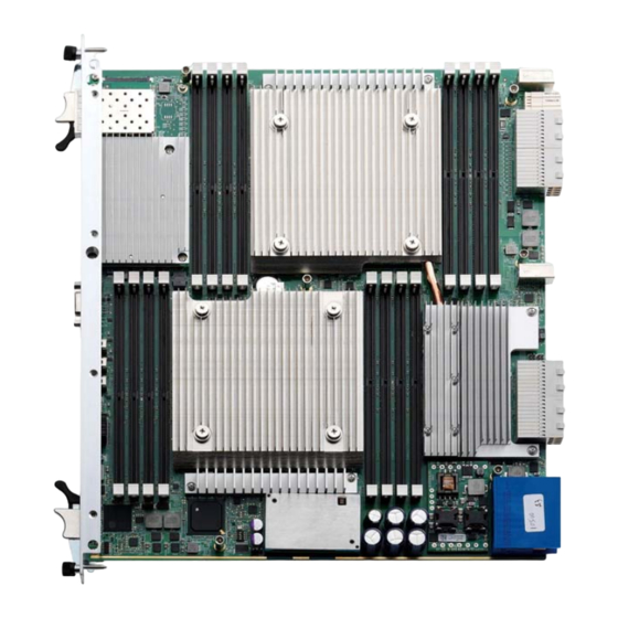
Page 12: Board Layout
Board Layout 2.3.1 aTCA-9710 Board Layout - Component Side DIMM_GH DIMM_EF CPU2 DIMM_AB DIMM_CD CPU1 PSU2 PSU1 Location Description Location Description XL710 JTAG debug header Reserved for PCH debug XL710 JTAG debug header Clear CMOS Ground connection IPMC Programming mode... -
Page 13: Atca-9710 Board Layout - Solder Side
2.3.2 aTCA-9710 Board Layout - Solder Side Location Description Clear CMOS HW Reset Button... -
Page 14: Atca-9710 Front Panel
2.3.3 aTCA-9710 Front Panel 10GbE (SFP) OOS LED IPMC Serial Debug Port BIOS/OS Boot OK RS-232 Serial Port IPMC Payload Power Authorized IPMC Chassis Identify Command Reset button Base and Fabric Channel LEDs Hot-Swap LED... -
Page 15: Status Led Definitions
2.3.4 Status LED Definitions The following sections describe the front panel Status LEDs: Hot-swap LED, OOS LED, BIOS/OS Boot OK LED, IPMC Payload Power Authorized LED and IPMC Chassis Identify Command LED. 2.3.4.1 Out of Service (OOS) LED Out of Service LED (Red) - Page 16 2.3.4.4 IPMC Chassis Identify Command LED IPMC Chassis Identify Command State Remark (Amber) Default Off Blinking Chassis Identify Command Active 2.3.4.5 Hot-swap LED Hot-swap LED FRU State FRU State Name (Blue) number FRU not installed FRU inactive Long blink...
- Page 17 2.3.4.6 Base and Fabric Channels LEDs Base and Fabric Channels LEDs FCH1 ACT (Amber) Fabric 1 Link FCH 2 ACT (Amber) Fabric 2 Link Blink when accessing (Amber) Blink when accessing (Amber) Ethernet I/O 40Gbps – ON Ethernet I/O 40Gbps –...
-
Page 18: Compliance
2.4 Compliance The aTCA-9710 conforms to the following specifications: PICMG 3.0 R2.0 ECN0002 AdvancedTCA PICMG 3.1 Ethernet over AdvancedTCA Option 9-KR NEBS Level 3 (design) -
Page 19: Functional Description
3 Functional Description CPU, Memory and Chipset 3.1.1 The Intel® Xeon® processor E5-2658 v3 implements several key technologies: Four channel Integrated Memory Controller supporting DDR4 Integrated I/O with up to 40 lanes for PCI Express Generation 3.0 Two point-to-point link interface based on Intel® QuickPath Interconnect (Intel® QPI) up to 9.6GT/s... -
Page 20: Memory
3.1.2 Memory The aTCA-9710 is a dual processor system with each Intel® Xeon® processor E5 2600 v3 series providing four memory channels supporting DDR4, 1600, 1866, 2133 MT/s DIMMs. The maximum memory capacity is 256GB with memory interleaving support. The 400/533/667/800/933 MHz differential memory clocks are driven by the Intel®... -
Page 21: Silicon Motion Sm750 Graphics Controller
3.1.4 Silicon Motion SM750 Graphics Controller The aTCA-9710 provides an analog VGA port on the front panel powered by a Silicon Motion SM750 2D graphics controller with the following features: PCI-Express x1 architecture 16MB integrated video DDR memory Low power consumption < 1.5W... -
Page 22: Smbus Devices
3.2.2 SMBus Devices The aTCA-9710 provides a System Management Bus (SMBus) hosted by the Intel® C612 PCH. The topology is shown in the diagram below. CPU DDR I2C Bus DIMM A1 0xA0 DIMM A2 0xA2 CPU 0 PCA9617 DIMM B1... -
Page 23: I/O Interfaces
480 Mb/s, 40 times faster than a full-speed USB (USB 1.1). One USB peripheral may be connected to each port. With the aTCA-R6280 RTM, the aTCA-9710 supports two additional USB ports on the I/O panel of the RTM. -
Page 24: Vga Interface
Note: The bandwidth of each XL-710 40G network controller is limited by the PCIe x8 Gen3 link to the CPU. The total bandwidth of each XL-710 40G network controller is approximately 50Gb/s. With the aTCA-R9700 RTM installed, the aTCA-9710 supports six 10GbE SFP+ ports from the Intel 82599ES Network Interface Controllers. -
Page 25: Serial Port
Signal Ground 3.3.5 Onboard mSATA Module The aTCA-9710 is equipped with an mSATA flash module (32GB, up to 256GB available) which supports a SATA 6.0Gb/s interface with sustained read to 550MB per second and sustained write up to 500MB per second. - Page 26 3.3.6.3 Shelf/Logic Ground Jumper Use CN7 to short Shelf Ground to Logic Ground. Shelf/Logic GND CN7 Setting Shorted Open (default) The locations of SW3, SW4 and CN7 are shown below: SW3 SW4 ...
-
Page 27: Intelligent Platform Management System
IPMI Sensors The following table lists all the sensors supported by the aTCA-9710. Six thresholds including Lower Non-Recoverable (LNR), Lower Critical (LC), Lower Non-Critical (LNC), Upper Non- Critical (UNC), Upper Critical (UC) and Upper Non-Critical (UNR) are defined for each voltage or temperature sensor. - Page 28 Threshold Sensor Type 5.00V SYS Volts 5.502 5.408 5.314 4.703 4.609 4.515 12.0V SYS Volts 13.24 12.76 11.32 11.08 10.84 1.05V VCCIO Volts 1.216 1.168 1.104 0.992 0.96 0.896 1.80V Volts 1.856 1.84 1.824 1.536 1.456 VCCIN_CPU0 1.80V Volts 1.856...
-
Page 29: Sensor Reading (Fru Hotswap Sensor)
4.1.1 Sensor Reading (FRU Hotswap Sensor) Byte Data field Request data Sensor Number (FFh = reserved) Response data Completion Code Sensor Reading. [7:0] - Not used. Write as 00h. Standard IPMI byte (See “Get Sensor Reading” in IPMI specification):... -
Page 30: Get Sensor Reading (Physical Ipmb-0 Sensor)
4.1.2 Get Sensor Reading (Physical IPMB-0 Sensor) Byte Data field Request data Sensor Number (FFh = reserved) Response data Completion Code [7] – IPMB B Override State 0b = Override state, bus isolated 1b = Local Control state - IPM Controller determines state of bus. -
Page 31: Watchdog Timer Sensor
4.1.3 Watchdog Timer Sensor Sensor Type Sensor Sensor Event Type Specific Code Offset Watchdog 2 This sensor is recommended for new IPMI v1.0 and later implementations. Timer expired, status only (no action, no interrupt) Hard Reset Power Down Power Cycle... -
Page 32: Version Change Sensor
4.1.4 Version Change Sensor Sensor Sensor Sensor Event Type Type Code Specific Offset Version 00h Intelligent change detected with associated Entity. Change Informational. This offset does not imply whether the intelligent change was successful or not. Only that a change occurred. -
Page 33: System Firmware Progress Sensor
4.1.5 System Firmware Progress Sensor Sensor Sensor Sensor Event Type Type Code Specific Offset System System Firmware Error (POST Error) Firmware The Event Data 2 field can be used to provide an event Progress extension code, with the following definition:... -
Page 34: Get Sensor Reading Command
Sensor Sensor Sensor Event Type Type Code Specific Offset Starting operating system boot process, e.g. calling Int 19h Baseboard or motherboard initialization reserved Floppy initialization Keyboard test Pointing device test Primary processor initialization 1Ah to FFh reserved 4.1.6 Get Sensor Reading Command... - Page 35 Byte Data field [2] - 1b = state 2 asserted [1] - 1b = state 1 asserted [0] - 1b = state 0 asserted For discrete reading sensors only. (Optional) (00h Otherwise) [7] - reserved. Returned as 1b. Ignore on read.
-
Page 36: Ipmi Commands
IPMI Commands The following table presents all the commands which are supported by the aTCA-9710 in different interfaces and compatible with IPMI v1.5 and PICMG 3.0 R2.0 ECN001. There are two interfaces implemented with IPMI command support. (1) KCS: OpenIpmi; (2) IPMB0: IPMBa & IPMBb... - Page 37 FRU Device Commands Get FRU Inventory Area Info ● ● Read FRU Data ● ● Write FRU Data ● ● PICMG Command HPM.1 Upgrade Commands (HPM.1) Get target upgrade capabilities ● ● Get component properties ● ● Abort Firmware Upgrade ●...
-
Page 38: Getting Started
5 Getting Started The aTCA-9710 has been designed for easy installation. However, the following standard precautions, installation procedures, and general information must be observed to ensure proper installation and to preclude damage to the board, other system components, or injury to personnel. -
Page 39: Installing And Removing The Atca-9710
5.2 Installing and Removing the aTCA-9710 5.2.1 Installing the Blade Follow these steps to install the aTCA-9710 blade to the chassis. Step 1 Carefully align the board edges with the chassis guide rails and push the blade inwards. - Page 40 Step 2 Check if the catch hooks and alignment pins at both ends of the module are correctly inserted into the proper openings. Push inwards on the handles until the blade is firmly seated in the chassis. (Do not force the handles if there is any abnormal resistance or it...
- Page 41 Step 3 Push the ejector handles inwards until it is locked.
- Page 42 Step 4 Lock both ends of the captive screws.
-
Page 43: Removing The Blade
5.2.2 Removing the Blade Follow these steps to remove the aTCA-9710 blade from the chassis. Step 1 Unlock both ends of the captive screws. - Page 44 Step 2 Pinch the lever and latch together then pull outwards to release the ejector handles at both ends. Lever Latch...
- Page 45 Step 3 Pull the blade outwards from the chassis until it is removed.
-
Page 46: Firmware Update Procedure
Step 1: Prepare an external host PC with Linux OS and connect it to the serial port on the aTCA-9710 via the COM port (USB Mini-B on the front panel). Put the IPMItool utility and new firmware image on the host PC. Enter the following command: Step 2: Enter “y”... -
Page 47: Update Over Kcs
5.3.2 Update over KCS Step1: Prepare an aTCA-9710 with Linux system. Enter the following command to make sure the ipmi_si and ipmi_devintf modules are loaded before the IPMItool utility can be used. Step2: Put IPMItool and “target image” in the Linux system then enter the following command: Step3: Select “y”... -
Page 48: Update Over Lan
The parameter specifies the IP address of the IPMC. Please follow the step to update firmware: Step1: Prepare an external x86 PC and connect the target aTCA-9710 via BASE Interface. Put IPMItool and “target image” on the x86 PC with Linux system. Enter the following command: Step2: Select “y”... -
Page 49: Bios
6.1 Entering the BIOS Setup Screen To enter the setup screen, follow these steps: Step 1: Power on the aTCA-9710. Step 2: Press the <DEL> key on a USB keyboard when you see the following text prompt on boot up screen. -
Page 50: Navigation
6.1.1 Navigation The BIOS setup/utility uses a key-based navigation system called hot keys. Most of the BIOS setup utility hot keys can be used at any time during the setup navigation process. These keys include <F1>, <F2>, <F3>, <F4>, <ESC>, <Enter>, <Arrow>... -
Page 51: Main Bios Setup Screen
The Main setup screen is shown below. System Language Choose the language of BIOS setup utility. So far, there is only “English” is supported on aTCA-9710. System Time/System Date Use these two options to change system time and date. Highlight System Time or System Date using the <Arrow>... - Page 52 System & Board Information The Main BIOS setup screen reports memory and board information. BIOS Vendor Reports the BIOS vendor of aTCA-9710’s BIOS. American Megatrend, Inc. is the BIOS vendor that aTCA-9710 is using. Core Version Shows what core version is used from AMI to develop aTCA-9710’s BIOS.
-
Page 53: Advanced Setup Screen
6.3 Advanced Setup Screen Select the Advanced tab from the setup screen to enter Advanced BIOS setup screen. You can select any of items in the left frame of the screen, such as CPU configuration, to go to the sub menu for that item. You can select an Advanced BIOS sub menu or option by highlighting it using the <Arrow>... - Page 54 Fabric 40G LAN3/4 PXE ROM Enable or Disable PXE ROM OF Fabric 40G LAN3/4. Set this value to Enabled/Disabled. RTM 10G LAN1/2 PXE ROM Enable or Disable PXE ROM OF RTM 10G LAN1/2. Set this value to Enabled/Disabled. RTM 10G LAN3/4 PXE ROM Enable or Disable PXE ROM OF RTM 10G LAN3/4.
-
Page 55: Acpi Settings
6.3.1 ACPI Settings You can use this screen to select options for the ACPI Advanced Configuration Settings. Use the up and down < Arrow > keys to select an item. Use the < + > and < - > keys to change the value of the selected option. A description of the selected item appears on the right side of the screen. -
Page 56: Nct5104D Super Io Configuration
6.3.2 NCT5104D Super IO Configuration You can use this screen to select options for the NCT5104D Super IO Configuration. Use the up and down < Arrow > keys to select an item. Use the < + > and < - > keys to change the value of the selected option. A description of the selected item appears on the right side of the screen. - Page 57 Serial PortGSIO200 Enable or Disable Serial Port (COM). Set this value to Enabled/Disabled.
-
Page 58: Serial Port Console Redirection
6.3.3 Serial Port Console Redirection You can use this screen to select options for the serial port console redirection settings. Use the up and down < Arrow > keys to select an item. Use the < + > and <... - Page 59 Console Redirection Settings The settings specify how the host computer and the remote computer (which the user is using) will exchange data. Both computers should have the same or compatible settings. The screen is shown below. Terminal Type VT100+ is the preferred terminal type for out-of-band management. Configuration options: VT100, VT100+, VT-UTF8, ANSI.
- Page 60 Stop Bits Stop bits indicate the end of a serial data packet. (A start bit indicates the beginning). The standard setting is 1 stop bit. Communication with slow devices may require more than 1 stop bit. Set this value to 1, 2.
-
Page 61: Pci Subsystem Settings
6.3.4 PCI Subsystem Settings You can use this screen to select options for the PCI Subsystem Settings. Use the up and down < Arrow > keys to select an item. Use the < + > and < - > keys to change the value of the selected option. -
Page 62: Network Stack Configuration
6.3.5 Network Stack Configuration You can use this screen to select options for the Network Stack Configuration. Use the up and down < Arrow > keys to select an item. Use the < + > and < - > keys to change the value of the selected option. -
Page 63: Csm Configuration
6.3.6 CSM Configuration You can use this screen to select options for the CSM Configuration. Use the up and down < Arrow > keys to select an item. Use the < + > and < - > keys to change the value of the selected option. -
Page 64: Trusted Computing
6.3.7 Trusted Computing Trusted computing is an industry standard to make personal computers more secure through a dedicated hardware chip, called a Trusted Platform Module (TPM). This option allows enabling or disabling the TPM support. Security Device Support Enable for BIOS support for security device. O.S. will not show Security Device. -
Page 65: Adlink Ipmi Settings
6.3.8 ADLINK IPMI settings You can use this screen to select options for the ADLINK IPMI settings. Use the up and down < Arrow > keys to select an item. Use the < + > and < - > keys to change the value of the selected option. -
Page 66: Intel Rc Setup
6.4 Intel RC Setup Select the Inte lRC Setup tab from the setup screen to enter the Intel RC Setup screen. You can select any of the items in the left frame of the screen, such as Processor Configuration, to go to the sub menu for that item. You can display an IntelRCSetup option by highlighting it using the <... -
Page 67: Processor Configuration
6.4.1 Processor Configuration You can use this screen to select options for the Processor Configuration settings. Use the up and down < Arrow > keys to select an item. Use the < + > and < - > keys to change the value of the selected option. A description of the selected item appears on the right side of the screen. - Page 68 Per-Socket Configuration Change Per-Socket settings. The screen is shown below Cores Enabled Number of Cores to Enable. 0 means all cores.
-
Page 69: Advanced Power Management Configuration
6.4.2 Advanced Power Management Configuration You can use this screen to select options for the Advanced Power Management Configuration. Use the up and down < Arrow > keys to select an item. Use the < + > and < - > keys to change the value of the selected option. A description of the selected item appears on the right side of the screen. - Page 70 CPU P State Control The screen is shown below EIST (P-states) When enabled, OS sets CPU frequency according load. When disabled, CPU frequency is set at max non-turbo. Set this value to Enable/Disable. Turbo Mode Enable or Disable CPU Turbo mode. Set this value to Enable/Disable.
-
Page 71: Common Refcode Configuration
6.4.3 Common RefCode Configuration You can use this screen to select options for the Common RefCode Configuration. Use the up and down < Arrow > keys to select an item. Use the < + > and < - >... - Page 72 Memory Map Set memory mapping settings. The screen is shown below Socket Interleave Below 4GB Splits the 0-4GB address space between two sockets, so that both sockets get a chunk of local memory below 4GB. Set this value to Enable/Disable.
-
Page 73: Iio Configuration
6.4.5 IIO Configuration You can use this screen to select options for the IIO Configuration. Use the up and down < Arrow > keys to select an item. Use the < + > and < - > keys to change the value of the selected option. -
Page 74: Pch Configuration
6.4.6 PCH Configuration You can use this screen to select options for the PCH Configuration. Use the up and down < Arrow > keys to select an item. Use the < + > and < - > keys to change the value of the selected option. -
Page 75: Server Mgmt Setup Screen
6.5 Server Mgmt Setup Screen You can use this screen to specify options for the Server Management settings. Use the up and down <Arrow> keys to select an item. Use <+> and <-> keys to change the value of the selected option. The settings are described in the following pages. The screen is... -
Page 76: Boot Setup Screen
6.6 Boot Setup Screen You can use this screen to specify options for the Boot configuration settings. Use the up and down <Arrow> keys to select an item. Use the <+> and <-> keys to change the value of the selected option. The settings are described in the following pages. The screen is shown as the below. -
Page 77: Security Setup Screen
6.7 Security Setup Screen System BIOS provides two levels of password protection. They are Administrator password and User password. The system can be configured that all users must enter password every time the system boots or when setup utility is executed, using either Administrator password or User password. -
Page 78: Save & Exit Setup Screen
6.8 Save & Exit Setup Screen Select Save & Exit tab from setup utility to enter Save & Exit BIOS setup screen. You can select an item by highlighting it using the <Arrow> keys. The Save & Exit BIOS setup screen is shown below. - Page 79 Discard Changes and Exit Select this option to quit setup without making any permanent changes to the system configuration. When selecting this item and then press <Enter>. The below message will be shown up and wait for the confirmation.
-
Page 80: Serial Over Lan
The aTCA-9710 supports 2 channels (channel 1/2) and 2 user IDs for SOL. You can refer to the following sections for more detailed information. Note: SOL does not support simultaneous login of more than one user. -
Page 81: Configure The Target Atca-9710
Build the source code and install IPMItool: make make install Now your remote client is ready to connect to the target the aTCA-9710. Note: The install must be run with root permissions to overlay the existing IPMItool utility in /usr/local/bin. -
Page 82: Linux System Setting
Add the following line to the init configuration file /etc/inittab. s1:12345:respawn:/sbin/agetty –L ttyS1 115200 vt100 Now the target aTCA-9710 is ready for SOL connection. 7.4 Establish SOL Connection Execute the following command from your remote client to establish the SOL Connection Command: ipmitool -I lanplus -H <Target IPMC IP >... - Page 83 The default values of the aTCA-9710 SOL parameters are listed in the table below Parameter Default Value Channel 1 IP Address 172.17.172.134 Channel 2 IP Address 172.17.172.135 User ID User Name adlinkuser Password adlinkuser Below are 2 samples to establish the SOL session via channel 1 with default user name...
-
Page 84: Drivers
8 Drivers The drivers for aTCA-9710 are available on the ADLINK website. Please visit the aTCA- 9710 product web site for more details: www.adlinktech.com We recommend using all the drivers provided on the ADLINK website to ensure driver compatibility. Contact ADLINK to get support for other operating system.. -
Page 85: Safety Instructions
Safety Instructions 1. Please read these safety instructions carefully. 2. Please keep this User‘s Manual for later reference. 3. One AC Inlets provided and service as Disconnect Devices, disconnect the equipment from both AC outlets use these AC Inlets before servicing or clearing. Use moisture sheet or cloth for cleaning. -
Page 86: Getting Service
5215 Hellyer Avenue, #110, San Jose, CA 95138, USA Tel: +1-408-360-0200 Toll Free: +1-800-966-5200 (USA only) Fax: +1-408-360-0222 Email: info@adlinktech.com ADLINK Technology (China) Co., Ltd. Address: 上海市浦东新区张江高科技园区芳春路 300 号 (201203) 300 Fang Chun Rd., Zhangjiang Hi-Tech Park, Pudong New Area Shanghai, 201203 China Tel: +86-21-5132-8988 Fax: +86-21-5132-3588 Email: market@adlinktech.com...
Need help?
Do you have a question about the aTCA-9710 and is the answer not in the manual?
Questions and answers