
Related Manuals for ADLINK Technology AMC-7000


Summary of Contents for ADLINK Technology AMC-7000
- Page 1 AMC-7000 AdvancedMC™ SATA Drive Module User’s Manual Manual Rev. 2.00 Revision Date: November 9, 2011 Part No: 50-1Z090-1000 Advance Technologies; Automate the World.
- Page 2 Revision History Revision Release Date Description of Change(s) 2.00 2011/11/09 Initial Release Revision History...
-
Page 3: Preface
AMC-7000 Preface Copyright 2011 ADLINK Technology Inc. This document contains proprietary information protected by copy- right. All rights are reserved. No part of this manual may be repro- duced by any mechanical, electronic, or other means in any form without prior written permission of the manufacturer. - Page 4 Using this Manual Audience and Scope The AMC-7000 User’s Manual is intended for hardware technicians and systems operators with knowledge of installing, configuring and operating AMC modules. Manual Organization This manual is organized as follows: Chapter 1, Overview: Introduces the AMC-7000, its features, and package contents.
- Page 5 AMC-7000 Conventions Take note of the following conventions used throughout this manual to make sure that users perform certain tasks and instructions properly. Additional information, aids, and tips that help users perform tasks. NOTE: NOTE: Information to prevent minor physical injury, component dam- age, data loss, and/or program corruption when trying to com- plete a task.
- Page 6 This page intentionally left blank. Preface...
-
Page 7: Table Of Contents
2 Installation ................3 Important Information about Your Chassis ......3 Before Installing or Removing the AMC....... 3 Module Hot Swap ..............5 Installing the AMC-7000 Module.......... 6 Removing the AMC Module..........7 3 Functional Description ............9 Overview................9 Power Regulator .............. - Page 8 Important Safety Instructions..........19 Getting Service ..............21 viii...
-
Page 9: List Of Tables
AMC-7000 List of Tables Table 4-1: AMC-7000 AMC Port Assignments ......11 Table 4-2: AMC Module Card-edge Interface Pin Assignment 12 Table 5-1: AMC-7000 Environmental Specifications ....15 Table 6-1: AMC-7000 LED Functions ........17 List of Tables... - Page 10 This page intentionally left blank. List of Tables...
-
Page 11: List Of Figures
AMC-7000 List of Figures Figure 1-1: AMC-7000 Assembly Diagram ........1 Figure 2-1: AMC Module Handle ..........6 Figure 3-1: AMC-7000 Functional Blocks ........9 Figure 6-1: AMC-7000 Front Panel Indicators ......17 List of Figures... - Page 12 This page intentionally left blank. List of Figures...
-
Page 13: Overview
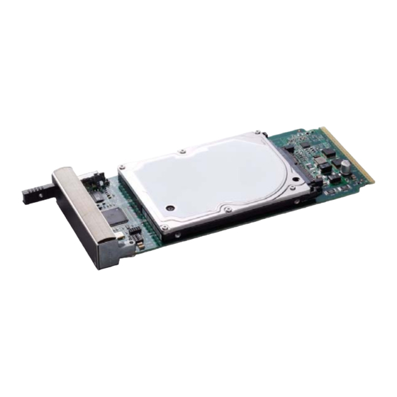
(MMC). Figure 1-1: AMC-7000 Assembly Diagram 1.2 Features The AMC-7000 is a single-width mid-size AMC Module with the following features: Supports a single 2.5" SATA hard drive on Port 2 General Advanced Mezzanine Card Features Ejector switches for hot swap... -
Page 14: Picmg Standards Compliance
1.3 PICMG Standards Compliance The AMC-7000 is fully compliant with the following PCI Industrial Computer Manufacturers Group (PICMG) specifications: PICMG AMC.0 R2.0 PICMG AMC.3 R1.0 storage signaling option This product must be protected from static discharge and physi- cal shock. Never remove any of the components except at a static-free workstation. -
Page 15: Installation
Installation This chapter contains the procedures for installing and removing the AMC-7000 AMC module. The AMC-7000 Module can be installed into an ATCA AdvancedMC carrier board or MicroTCA chassis with slots designed to accept AMC.3 installations. The module slot height must properly match the panel height fitted to the AMC. - Page 16 EMI barrier is open, devices may cause or be susceptible to excessive interference. Understanding Hot Swap Your AMC-7000 is electrically designed for hot swap within a fully powered chassis. To facilitate hot swap, there is a blue LED on the front faceplate. This LED is under software control.
-
Page 17: Module Hot Swap
2.3 Module Hot Swap This section describes a recommended procedure for installing a board module in a chassis. The AMC-7000 module has a latching mechanism. The Latch Mechanism includes the module handle with an integrated multi-position shaft and micro-switch (see figure below). -
Page 18: Installing The Amc-7000 Module
Figure 2-1: AMC Module Handle 2.4 Installing the AMC-7000 Module This section describes a recommended procedure for installing a board module in a chassis. Before you install your module, please read all cautions, warnings, and instructions presented in this section. -
Page 19: Removing The Amc Module
LED will blink and then turn off, indicating that the module has been placed in operation. 2.5 Removing the AMC Module The AMC-7000 is hot-swappable and can be removed from the chassis without powering down the associated host carrier or chassis. This section describes the recommended procedure for removing an AMC module. - Page 20 Once this is done you can extract the module by pulling on the module handle. 5. WARNING: Some AMC-7000 models may display this symbol to indicate the possible presence of a hot surface or component reaching up to 85ºC. To reduce the risk of injury from a hot component when servicing, allow the surface to cool before touching.
-
Page 21: Functional Description
This chapter provides a functional description of the major compo- nents and devices on the AMC-7000. 3.1 Overview The AMC-7000 contains three major functional blocks. These are: 1. The Serial Storage interface 2. The Power Regulator, and 3. The IPMI subsystem (Module Management Controller - MMC) The following block diagram illustrates the major components and switch locations on the AMC-7000. -
Page 22: Power Regulator
3.2 Power Regulator The Power Regulator is the part of the module that generates the required power from the payload power (+12V) that is delivered to the module through the AMC connector. This power is current lim- ited by the onboard regulator. 3.3 IPMI Subsystem The IPMI subsystem provides management control for the board. -
Page 23: Connector Pin Assignments
This chapter provides connector pin assignments for AMC-7000. This module is AMC.3 compliant and uses Port 2 as defined in the AMC.3 specification. 4.1 AMC-7000 Port Assignments Below are the specific ports that are used by the AMC-7000. All other pins match the AMC.0 specification. Port Signal AMC.3 Serial Storage Port 2... - Page 24 Pin# Signal Pin# Signal No Connect AMC_PS1-L No Connect P3V3_AMC_MP AMC_GA0 No Connect No Connect No Connect No Connect No Connect No Connect No Connect No Connect No Connect No Connect No Connect No Connect No Connect No Connect AMC_GA1 No Connect No Connect No Connect...
- Page 25 AMC-7000 Pin# Signal Pin# Signal SATA_TX-P No Connect SATA_TX-N' No Connect No Connect No Connect No Connect No Connect No Connect No Connect No Connect No Connect ENABLE_L No Connect No Connect No Connect No Connect No Connect No Connect...
- Page 26 Pin# Signal Pin# Signal No Connect No Connect No Connect No Connect No Connect No Connect No Connect No Connect No Connect No Connect No Connect No Connect IPMB_SDA_O No Connect No Connect No Connect No Connect No Connect No Connect No Connect No Connect No Connect...
-
Page 27: Specifications
Specifications This chapter contains the environmental and mechanical specifi- cations for the AMC-7000. The environmental specifications relate to and vary with the SATA hard drive that the AMC-7000 is config- ured with. 5.1 Hard Drive Operation and Storage Specifications Specification... - Page 28 This page intentionally left blank. Specifications...
-
Page 29: Front Panel Indicators
AMC-7000 Front Panel Indicators The faceplate of the AMC-7000 module has 2 LED indicators. The figure and table below describe their functions. Figure 6-1: AMC-7000 Front Panel Indicators Indicator Color State Function Management power available to the module and the module can... - Page 30 This page intentionally left blank. Front Panel Indicators...
- Page 31 AMC-7000 Important Safety Instructions Please read and follow all instructions marked on the product and in the documentation before operating the system. Retain all safety and operating instructions for future use. Please read these safety instructions carefully. Please keep this User’s Manual for future reference.
- Page 32 Openings in the case are provided for ventilation. Do not block or cover these openings. Make sure there is adequate space around the system for ventilation when setting up the work area. Never insert objects of any kind into the ventila- tion openings.
- Page 33 Address: 5215 Hellyer Avenue, #110, San Jose, CA 95138, USA Tel: +1-408-360-0200 Toll Free: +1-800-966-5200 (USA only) Fax: +1-408-360-0222 Email: info@adlinktech.com ADLINK Technology (China) Co., Ltd. Address: (201203) 300 Fang Chun Rd., Zhangjiang Hi-Tech Park, Pudong New Area, Shanghai, 201203 China Tel: +86-21-5132-8988 Fax:...
- Page 34 Address: 84 Genting Lane #07-02A, Cityneon Design Centre, Singapore 349584 Tel: +65-6844-2261 Fax: +65-6844-2263 Email: singapore@adlinktech.com ADLINK Technology Singapore Pte. Ltd. (Indian Liaison Office) Address: No. 1357, "Anupama", Sri Aurobindo Marg, 9th Cross, JP Nagar Phase I, Bangalore - 560078, India Tel: +91-80-65605817 Fax: +91-80-22443548 Email: india@adlinktech.com...
Need help?
Do you have a question about the AMC-7000 and is the answer not in the manual?
Questions and answers