
Related Manuals for ADLINK Technology aTCA-80606PA


Summary of Contents for ADLINK Technology aTCA-80606PA
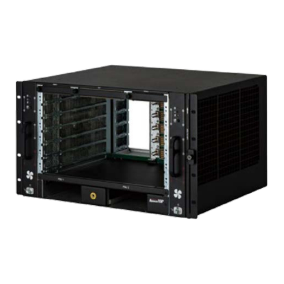
- Page 1 6U 6-Slot AC-Powered AdvancedTCA® Shelf User‘s Manual Manual Rev.: Revision Date: December 20, 2018 Part No.: 50-1G047-1000...
-
Page 2: Preface
Preface Copyright © 2018 ADLINK Technology, Inc. This document contains proprietary information protected by copyright. All rights are reserved. No part of this manual may be reproduced by any mechanical, electronic, or other means in any form without prior written permission of the manufacturer. -
Page 3: Table Of Contents
Table of Contents Preface .............................. 2 Safety ............................5 1.1 Safety Symbols used in this document ................5 1.2 General Safety Precautions ..................... 5 1.3 Reference and Architecture Specifications ............... 5 1.4 Product Definition ......................6 1.5 Terms and Acronyms ....................... 6 Hardware Platform ......................... - Page 4 8.2 Cooling Capacity .......................24 8.2.1 Front Board Air Distribution .................24 8.2.2 Rear Board Air Distribution .................25 Shelf Management ........................26 9.1 Shelf Managers .......................26 9.2 Introduction ........................27 9.3 Front Panel Components ....................28 9.4 Hardware Address ......................28 Technical Data ........................29 10.1 Shelf Mechanical Dimensions ..................30...
-
Page 5: Safety
1 Safety The intended audience of this User’s Manual is system integrators and hardware/software engineers. 1.1 Safety Symbols used in this document Hazardous voltage! This is the electrical hazard symbol. It indicates that there are dangerous voltages inside the Shelf. -
Page 6: Product Definition
1.4 Product Definition The aTCA-80606PA is a 6 U / 6-Slot AdvancedTCA Shelf for fault-tolerant / high-availability applications. • Dual-Star Backplane, bussed IPMB. It is designed to work with two redundant Shelf Managers. Fans controlled by the Shelf Manager or through autonomous via fan controller. -
Page 7: Hardware Platform
2 Hardware Platform 6U/19’’ chassis with front card cage for ATCA boards and rear card cage for ATCA RTM board. The chassis is designed for easy access of any Field-Replaceable Units (FRU). • 6-slot ATCA backplane with dual star Fabric Interface, Dual Star Base Interface and bussed IPMB interface, supporting four 8U node board slots and two 8U hub board slots. - Page 8 Figure 2: Rear View 8. Power input 2 10. ESD Wrist Strap 9. Shelf Ground Terminal 11. Power input 1...
-
Page 9: Atca Backplane
3 ATCA Backplane The 6-slot ATCA monolithic backplane provides: • Four ATCA Node slots • Two ATCA Hub slots • Two dedicated Shelf Manager slots • Two PEM slots • Two fan Tray slots Within the Shelf, there is one fixed board-backplane. This board is completely passive and is not Field-Replaceable Units. -
Page 10: Update Channel Interface
3.5 Update Channel Interface The Update Channels are wired between two redundant ATCA Backplane slots as 10 differential pairs with 100 Ohms impedance (see Table 2). The Update Channel is intended to pass information between two redundant ATCA Blades. -
Page 11: Intelligent Platform Management Bus (Ipmb)
3.6 Intelligent Platform Management Bus (IPMB) The Shelf uses an Intelligent Platform Management Bus (IPMB) for management communications among all ATCA Boards and the Shelf Managers. The reliability of the IPMB is improved by the addition of a second IPMB, with the two IPMBs referenced as IPMB-A and IPMB-B. -
Page 12: Logic Ground
3.8 Logic Ground The ATCA Backplane provides a mechanism to connect Logic Ground and Shelf Ground. To connect Logic Ground and Shelf Ground, the mounting screws at the positions marked by arrow must be fixed. Figure 4: Logic Ground By default, Logic Ground and Shelf Ground are isolated, the chassis is shipped without the mounting screws at the marked positions. -
Page 13: Air Filter
4 Air Filter 4.1 Introduction The ATCA Shelf provides a front-replaceable air filter. The filter element is an open cell polyurethane foam special coating to provide improved fire retardation and fungi resistance. The filter meets the requirements of the Telcordia Technologies Generic Requirements GR-78-CORE specification. -
Page 14: Shelf Ground Connection
5 Shelf Ground Connection Hazardous voltage! Before powering-up the Shelf, make sure that the Shelf Ground terminals are connected to Protective Earth (PE) of the building. The ATCA Shelf provides a Shelf ground terminal at the upper rear side. The Shelf ground terminal provides two threads (M5) with a 16.0mm spacing between thread centers to... -
Page 15: Fan Trays
6 Fan Trays 6.1 Introduction The 6 Slot ATCA Shelf contains two hot-swappable Fan Trays arranged in a side to side configuration for maximum air flow. The Fan Trays are locked into the Shelf by a mini compression latch with indicator. A hot swap push button is used to provide hot swap functionality. -
Page 16: Autonomous Mode
The system is designed to run indefinitely with any single fan failure. When one fan fails, all other fans are increased to full speed. The Fan Tray has sufficient cooling capacity to keep the Shelf cooled with a single fan failure. -
Page 17: Fan Tray Signals
6.3 Fan Tray Signals The Fan Tray provides signals for: • Fuse monitoring • Status of the Hot Swap Controller • Fan Speed • Temperature These signals are controlled by the IPM Controller devices on the Fan Tray PCB. The Shelf Manager has access to these signals via IPMB. -
Page 18: Fan Tray Connector Pin Assignment
6.5 Fan Tray Connector Pin Assignment Table 6: Fan Tray Connector Pin Assignment Pin# Signal Description Pin# Signal Description -48V_B -48VDC Feed B -48V_A -48VDC Feed A -48V_B -48VDC Feed B -48V_A -48VDC Feed A -48V_B -48VDC Feed B... -
Page 19: Fan Tray Ipmb Addresses
6.6 Fan Tray IPMB Addresses Geographic address pins H2 at the Fan Tray Backplane connector determine the hardware addresses of the devices. Table 7: Fan Tray IPMB address... -
Page 20: Power
7 Power Hazardous voltage! Before working ensure that the power is removed from the power connection cables. The Power Supplies are not included with the Shelf. The Shelf accepts Huawei R4850 serial power supplies. The Shelf can be powered with 230VAC line voltage or 240HVDC input depending on PSU type. -
Page 21: Power Distribution
7.2 Power Distribution Figure 7: Power Distribution... -
Page 22: Ac Power Supply Units (Psus)
7.3 AC Power Supply Units (PSUs) The AC PSUs with front-to-back airflow are hot-pluggable from the front side. The Shelf Manager can monitor the PSUs through the IPMC of the fan tray. The fan tray access the PSUs through an I2C bus to CAN bus bridge on the Power Distribution Board, since the PSUs only support CAN bus communication. -
Page 23: Power Branches
7.4 Power Branches Power branches within the Shelf originate from the PEM and powers all the blades, the Shelf Managers, and the Fan Trays. The Power is divided in 2 output branches towards the backplane. If the joint power capability of all ATCA boards assigned to a branch is greater than the calculated branch power, the Shelf Manager will not power-on all boards. -
Page 24: Thermal
8 Thermal 8.1 System Airflow Path The 6 slots ATCA Shelf provides an airflow using two Fan Trays at right and left sides of the Shelf. Each Fan Tray has 6 fans moving air from the right side to the left side of the Shelf in a push-pull arrangement. This arrangement provides excellent airflow as well as fault tolerance in the unlikely event of a fan failure. -
Page 25: Rear Board Air Distribution
8.2.2 Rear Board Air Distribution The airflow is measured with impedance boards acc. to the PICMG 3.0 R3.0 specification. • Rear board pressure drop: 24 Pa at 0.14 m³/min... -
Page 26: Shelf Management
9 Shelf Management The ATCA Shelves are designed to work with two redundant Shelf Managers in dedicated Shelf Manager slots. Upon request also a version with on-blade shelf management is available. With on- blade shelf management, the I²C components of the PEMs and the SEEPROM are connected to the internal I²C bus on the Fan Trays. -
Page 27: Introduction
9.2 Introduction The Shelf Manager is a 78mmX280mm board that fits into a dedicated Shelf Manager slot in an ATCA Shelf. The Shelf Manager has two main responsibilities: 1. Manage/track the FRU population and common infrastructure of a Shelf, especially the power, cooling and interconnect resources and their usage. -
Page 28: Front Panel Components
9.3 Front Panel Components Figure 13: Shelf Manager Front Panel Components 9.4 Hardware Address The Shelf Manager reads the hardware address and parity bit from the backplane connector of the Dedicated Shelf Manager slot. Geographic address pins (HA0, HA7) at the Backplane connector determine bit 0 and bit 7, bit 1...6 are hardware-coded on the Shelf Manager... -
Page 29: Technical Data
10 Technical Data Table 10: Technical Data Physical Dimensions Height Width 482.6 mm (19“) Depth (w/o handles) 426.65 mm Weight Shipping weight completely assembled 36 Kg with packaging Shelf weight completely assembled 19 Kg Power AC Input voltage nom. -
Page 30: Shelf Mechanical Dimensions
10.1 Shelf Mechanical Dimensions All dimensions below are in mm. Figure 14: Front View Dimensions Figure 15: Side View Dimensions... -
Page 31: Getting Service
Address: 5215 Hellyer Avenue, #110, San Jose, CA 95138, USA Tel: +1-408-360-0200 Toll Free: +1-800-966-5200 (USA only) Fax: +1-408-360-0222 Email: info@adlinktech.com ADLINK Technology (China) Co., Ltd. Address: 300 Fang Chun Rd., Zhangjiang Hi-Tech Park, Pudong New Area Shanghai, 201203 China 上海市浦东新区张江高科技园区芳春路300号 (201203) Tel: +86-21-5132-8988 Fax: +86-21-5132-3588 Email: market@adlinktech.com...
Need help?
Do you have a question about the aTCA-80606PA and is the answer not in the manual?
Questions and answers