Table of Contents

Subscribe to Our Youtube Channel
Related Manuals for ADLINK Technology AmITX-CF-I


Summary of Contents for ADLINK Technology AmITX-CF-I
- Page 1 AmITX-CF-I User’s Manual Mini-ITX Embedded Motherboard with and 9 Gen Intel® Core™ i7/i5/i3 Processors and Intel® Q370/H310 Chipset Manual Rev.: Revision Date: November 3, 2020 Part Number: 50-1X017-1000 Leading EDGE COMPUTING...
- Page 2 Preface Copyright Copyright © 2020 ADLINK Technology, Inc. This document contains proprietary information protected by copyright. All rights are reserved. No part of this manual may be reproduced by any mechanical, electronic, or other means in any form without prior written permission of the manufacturer.
-
Page 3: Table Of Contents
AmITX-CF-I Table of Contents Preface ..........................ii List of Figures ........................v List of Tables........................vi Introduction........................1 Packing List........................1 Optional Accessories ......................1 Specifications ......................3 Core System ........................3 Rear I/O Connectors .......................3 Internal Headers and Connectors ...................4 Form Factor........................4 Video ..........................4 Audio .......................... -
Page 4: Preface
Security ......................... 55 Boot..........................57 Save & Exit ........................58 Safety Instructions......................59 Getting Service.........................60 Preface... -
Page 5: List Of Figures
AmITX-CF-I List of Figures Figure 1: AmITX-CF-I Functional Block Diagram ..................7 Figure 2: AmITX-CF-I Rear I/O ........................9 Figure 3: AmITX-CF-I Component-Side Connectors ................10 Figure 4: AmITX-CF-I Mechanical Dimensions ..................12 Figure 5: Jumper and Switch Locations ....................26 Preface... - Page 6 List of Tables Table 1: AmITX-CF-I Processors ......................1 Table 2: System Memory Map ......................31 Table 3: I/O Map............................ 32 Table 4: IRQ Map ..........................34 Preface...
-
Page 7: Introduction
The AmITX-CF-I features one DisplayPort, one HDMI, one DVI-D, dual Gigabit Ethernet ports, USB 3.0 ports, USB 2.0 ports, and SATA 6 Gb/s ports. Expansion is provided by one PCIe x16, and one mini-PCIe slot. The onboard feature connector provides GPIO, SMBus, and I C support. - Page 8 This page intentionally left blank. Introduction...
-
Page 9: Specifications
AmITX-CF-I Specifications Core System Desktop 8th Generation Intel® Core™ i7/i5/i3 and Pentium®/Celeron® Processor, LGA1151 socket Intel® Core™ i7-8700, 3.2GHz, 12M Cache, 65W TDP, LGA1151, DDR4 2666MHz support (6C/12T) Intel® Core™ i7-8700T, 2.4GHz 12M Cache, 35W TDP, LGA1151, DDR4 2666MHz support (6C/12T) Intel®... -
Page 10: Internal Headers And Connectors
Internal Headers and Connectors PCIe x16 (Gen3) PCI Express Slots 1x Mini PCIe (full/half size), supports PCIe x1 Gen2, USB 2.0 2x USB 3.1 Gen1 onboard header (H310: not available) 2x USB 2.0 onboard header 4x SATA 6.0 Gb/s connectors. Software RAID support 0/1/5/10 (H310: 2x SATA, no RAID support) SATA 1x M.2 (2280) 4x RS-232 headers... -
Page 11: Trusted Platform Module (Tpm)
AmITX-CF-I Trusted Platform Module (TPM) Infineon SLB9665TT2.0 (optional) TPM 2.0 Power Specification AT and ATX mode Power Modes +12V (5.51A), +5V (1.466A), +3.3V (2.09A), 5VSB (0.6A) Power Requirement ACPI 5.0 compliant Power Management Supports S0, S4, S3, S5, (Wake-on-USB S3/S4, WoL S3/S4/S5) Power States 1x 24-pin ATX connector;... -
Page 12: 2.11 Temperatures
2.11 Temperatures 0°C to 60°C Standard Operating Temperature -40°C to 85°C Storage Temperature 2.12 Environmental 60°C @ 95% RH non-condensing Humidity 3.5Grms, 5-500Hz, Non-operation Vibration 2.13 Operating Systems Microsoft Windows 10 64bit, Fedora 30 64-bit, Ubuntu 18.10 LTS 64bit Standard Support Specifications... -
Page 13: 2.14 Functional Block Diagram
SATA #3 SATA Port 3 PCIe #16 LPC Header SATA #4 SATA Port 4 PCIe #17 Q370 only 8-bit GPIO GPIO Header x1 GPIO PCIe #15 PCIe #5 Mini-PCIe USB 2.0 USB 2.0 #10 Figure 1: AmITX-CF-I Functional Block Diagram Specifications... - Page 14 This page intentionally left blank. Specifications...
-
Page 15: Mechanical Layout
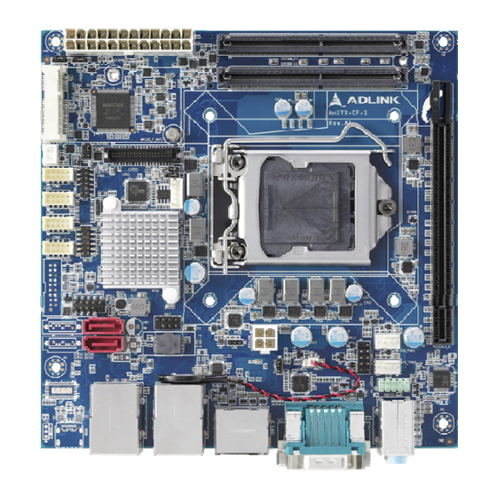
Mechanical Layout Connector Locations 3.1.1 Rear I/O Connectors Line In HDMI USB 3.1 Gen 1/2 MIC In Line Out Figure 2: AmITX-CF-I Rear I/O 3.1.2 Component-Side Connectors ATX Power Connector 2x DDR4 SODIMM Mini PCIe LVDS Inverter Power Connector LVDS... -
Page 16: Figure 3: Amitx-Cf-I Component-Side Connectors
Figure 3: AmITX-CF-I Component-Side Connectors Mechanical Layout... -
Page 17: Mechanical Dimensions
AmITX-CF-I Mechanical Dimensions Top View Dimensions: mm Mechanical Layout... -
Page 18: Figure 4: Amitx-Cf-I Mechanical Dimensions
Rear View Dimensions: mm Figure 4: AmITX-CF-I Mechanical Dimensions Mechanical Layout... -
Page 19: Thermal Solutions
AmITX-CF-I Thermal Solutions LGA1150 CPU Cooler, H=30.0mm, 45W Standard Temp.: 0°C to 60°C P/N: 32-20513-0000 LGA1150 CPU Cooler, H=46.05mm, Standard Temp.: 0°C to 60°C P/N: 32-20512-0000 LGA1150 CPU Cooler, H=50.2mm, 95W Standard Temp.: 0°C to 60°C P/N: 32-20113-0000 LGA1150 CPU Cooler, H=61.4mm, 95W Standard Temp.: 0°C to 60°C... - Page 20 This page intentionally left blank. Mechanical Layout...
-
Page 21: Connectors And Jumpers
AmITX-CF-I Connectors and Jumpers See 3.1 Connector Locations on page 9. Rear IO Connectors 4.1.1 DisplayPort One DisplayPort v1.2 specification port1 up to 4096 x 2304 @ 60Hz Signal Signal DP1_CON_DP0 DP1_CON_DN0 DP1_CON_DP1 DP1_CON_DN1 DP1_CON_DP2 DP1_CON_DN2 DP1_CON_DP3 DP1_CON_DN3 DP1_HDMI_DNG_DET DP_CFG2... - Page 22 4.1.3 One DVI-D port up to 1920 x 1200 @ 60 Hz Signal Signal DVI1_CON_DN2 DVI1_CON_DP2 DVI1_B_HPD DVI1_CON_DN0 DVI1_DDC_CLK DVI1_CON_DP0 DVI1_DDC_DATA DVI1_CON_DN1 DVI1_CON_DP1 DVI1_CON_CKP DVI1_CON_CKN 4.1.4 Ethernet Connectors (LAN1, LAN2) Dual 10/100/1000Mbit/s LAN Ethernet controllers based on Realtek RTL8111G, supporting PXE and WOL over both LANs 10BASE-T/ 1000BASE-T...
- Page 23 AmITX-CF-I 4.1.5 USB Connectors (USB12, USB34) 4x USB 3.1 Gen2 (H310: USB 3.1 Gen1) 5V supply for external devices 5Vsb is supplied during power down to allow wakeup on USB device activity during S3~S4 state 1.5A for device power supply protected by a resettable 2A fuse...
- Page 24 4.1.6 Serial COM Port Connector (COM1) COM1 supports RS-232/422/485, selected in BIOS. RS-232 Signal Signal DCD# DSR# RTS# CTS# DTR# RS-422 Signal Signal TXD422- TXD422+ RXD422+ 8 RXD422- RS-485 Signal Signal 485DATA- 485DATA+ 7 4.1.7 Audio Connectors • One Line-out, one Line-in, and one Mic-in on rear I/O •...
-
Page 25: Internal Connectors
+5V (Standby) +12V +12V +3.3V 4.2.2 ATX 12V Power Connector (ATX12V1) Signal Signal +12V or 16V~24V DC +12V or 16V~24V DC 4.2.3 SATA Connectors (SATA1/2/3/4) Four SATA 6 Gbps ports are available on AmITX-CF-I (H310: 2x SATA). Signal Connectors and Jumpers... - Page 26 4.2.4 USB 2.0 Header (USB78) 2x USB 2.0. 2x5-pin 2.54mm pitch header. Signal Signal +5VDC +5VDC KEY (no pin) USB Cable (optional): USB 2.0 Header to 2x Female Type-A Cable (length 150mm), P/N: 30-21625-0000-B0 Connectors and Jumpers...
- Page 27 AmITX-CF-I 4.2.5 USB 3.0 Connector (USB56) 2x USB 3.1 Gen1 (H310: not available). 2x10-pin 2.00mm pitch standard wafer connector. Signal Signal +5VDC USB_P6 USB3_RX_N7 USB_N6 USB3_RX_P7 USB3_TX_P8 USB3_TX_N7 USB3_TX_N8 USB3_TX_P7 USB3_RX_P8 USB_N5 USB3_RX_N8 USB_P5 +5VDC KEY (no pin) USB Cable (optional): USB 3.0 Header to 2x Female Type-A Cable (length 150mm), P/N: 30-21597-1000-A0...
- Page 28 4.2.7 CPU Fan and System Fan Connectors (CPU_FAN1, SYS_FAN1) Signal Description Ground +12 V FAN Power Tach FAN Tachometer FAN PWM 4.2.8 Serial COM Port Connector (COM2/3/4/5) Four internal Serial Port (COM2-4). Serial Ports are over-current protected. 2x5-pin 2.00mm pitch standard wafer connector. Serial Port Functions COM2...
- Page 29 AmITX-CF-I 4.2.9 LVDS (JLVDS1) 2x20-pin 1.25mm pitch connector Signal Signal VDD_LVDS VDD_LVDS VDD_LVDS VDD_LVDS LVDS_A0- LVDS_B0- LVDS_A0+ LVDS_B0+ LVDS_A1- LVDS_B1- LVDS_A1+ LVDS_B1+ LVDS_A2- LVDS_B2- LVDS_A2+ LVDS_B2+ LVDS_A_CLK- LVDS_B_CLK- LVDS_A_CLK+ LVDS_B_CLK+ DDC_CLK DDC_DATA LVDS_A3- LVDS_B3- LVDS_A3+ LVDS_B3+ LCDS_VDD_EN 4.2.10 LVDS Inverter Power Connector (JBKL1) 1x5-pin 2.00 mm pitch standard wafer connector...
- Page 30 4.2.11 Front Panel Header (F_PANEL1) 2x5-pin 2.54mm pitch header The front panel connector provides Audio Mic-In / Line Out, ATX power switch, Reset, HDD LED, and active LED, and system LED. Signal In/Out Description Signal In/Out Description HDD Activity LED Power LED Hard disk LED Power LED...
- Page 31 AmITX-CF-I 4.2.14 8-bit GPIO (JDIO1) 2x6-pin 2.00mm pitch header Signal Signal GPIO0 GPIO4 GPIO1 GPIO5 GPIO2 GPIO6 GPIO3 GPIO7 SMBCLK SMBDATA +3.3VDC 4.2.15 Debug Header (JLPC1) 2x6-pin 2.00mm pitch header Signal Signal VCC3 LPC_AD3 PLTRST LPC_AD1 LPC_AD2 LPC_FRAME 8 LPC_AD0...
-
Page 32: Jumper And Switch Settings
Jumper and Switch Settings ATX/AT Mode Jumper (JPSON1) LVDS PWN/LINEAR Selection (JBKL2) LVDS Power Selection (JLVDSVDD1) LVDS Brightness Power Selection (JBKLVOL1) Clear CMOS (CLCMOS1) Figure 5: Jumper and Switch Locations 4.3.1 ATX/AT Mode Jumper Selection (JPSON1) JPSON1 ATX/AT Mode ATX (default) 4.3.2 Clear CMOS (CLCMOS1) CLCMOS1... - Page 33 AmITX-CF-I 4.3.3 LVDS Brightness Power Selection (JBKLVOL1) JBKLVOL1 Brightness 3.3V (default) 4.3.4 LVDS Power Selection (JLVDSVDD1) JLVDSVDD1 Signal 3.3V (default) 4.3.5 LVDS PWM/LINEAR Selection (JBKL2) JBKL2 LVDS PWM/LINEAR Linear mode (default) PWM mode Connectors and Jumpers...
- Page 34 This page intentionally left blank. Connectors and Jumpers...
-
Page 35: Driver Installation
AmITX-CF-I Driver Installation Drivers can be downloaded through the following link. https://www.adlinktech.com/Products/Industrial_Motherboards_SBCs/Mini-ITXEmbeddedBoards/AmITX-CF-I Driver Installation... - Page 36 This page intentionally left blank. Driver Installation...
-
Page 37: System Resources
AmITX-CF-I System Resources System Memory Map Table 2: System Memory Map Hex Range Device A0000-BFFFF Intel UHD Graphic 630 A0000-BFFFF PCI Express Root Complex 40000000-403FFFFF Motherboard resources 90000000-9FFFFFFF Intel UHD Graphic 630 90000000-DFFFFFFF PCI Express Root Complex A0000000-A0003FFF Realtek PCIe GbE Family Controller... -
Page 38: I/O Map
Hex Range Device FD6F0000-FDFFFFFF Mother resources FE000000-FE01FFFF Mother resources FE010000-FE010FFF Intel SPI Controller FE200000-FE7FFFFF Mother resources FED00000-FED003FF High precision event timer FED10000-FED17FFF Mother resources FED18000-FED18FFF Mother resources FED19000-FED19FFF Mother resources FED20000-FED3FFFF Mother resources FED45000-FED8FFFF Mother resources FED90000-FED93FFF Mother resources FED90000-FED93FFF Mother resources FEE00000-FEEFFFFF Mother resources... - Page 39 AmITX-CF-I Hex Range Device 0067-0067 Motherboard Resources 0070-0070 Motherboard Resources 0080-0080 Motherboard Resources 0092-0092 Motherboard Resources 00A0-00A1 Programmable interrupt controller 00A4-00A5 Programmable interrupt controller 00A8-00A9 Programmable interrupt controller 00AC-00AD Programmable interrupt controller 00B0-00B1 Programmable interrupt controller 00B2-00B3 Motherboard resources 00B4-00B5...
-
Page 40: Interrupt Request (Irq) Map
Hex Range Device 3000-30FF Realtek PCIe GbE Family Controller 3000-3FFF Intel PCI Express Root Port #12 4000-40FF Realtek PCIe GbE Family Controller #2 4000-4FFF Intel PCI Express Root Port #11 5000-503F Intel UHD Graphic 630 5060-507F Intel 300 Series Chipset Family SATA AHCI Controller 5080-5083 Intel 300 Series Chipset Family SATA AHCI Controller 5090-5097... -
Page 41: Bios Setup
AmITX-CF-I BIOS Setup Menu Structure This section presents the six primary menus of the BIOS Setup Utility. Use the following table as a quick reference for the contents of the BIOS Setup Utility. The subsections in this section describe the submenus and setting options for each menu item. -
Page 42: Main
Options Description BIOS Information BIOS Vendor American Megatrends Core Version 5.13 0.45 x64 Compliancy UEFI 2.7; PI 1.6 Project Version AmITX-CF-I-xxxx_xxxxx Build Date and Time Info only Access Level Administrator Memory Information Total Memory Info only Memory Frequency Info only... -
Page 43: Advanced
AmITX-CF-I Advanced This menu contains the settings for most of the user interfaces in the system. Feature Options Description CPU Configuration CPU Configuration Parameters. PCH-FW Configuration Configure Management Engine Technology Parameters. ACPI Setting System ACPI Parameters. NCT6106D Super IO System Super IO Chip Parameters. - Page 44 Feature Options Description (SGX) Enabled Software Controlled Select Owner EPOCH input There are three Owner EPOCH modes (Each EPOCH No Change in Owner ECOPHs type is 64bit): no change in owner epoch, change to new Change to New Random Owner random owner epoch and manually entered by user.
- Page 45 AmITX-CF-I 7.3.2 PCH-FW Configuration Feature Options Description ME Firmware Version Info only ME Firmware Mode Info only ME Firmware SKU Info only ME Firmware Status 1 Info only ME Firmware Status 2 Info only ME State Enabled ME Lock Control ME UnLock switch function.
- Page 46 7.3.4 NCT6106D Super IO Configuration Feature Options Description NCT6106D Super IO Configuration Super IO Chip NCT6106D Serial Port 1 Configuration Set Parameters of Serial Port 1. Serial Port 2 Configuration Set Parameters of Serial Port 2. Serial Port 3 Configuration Set Parameters of Serial Port 3.
- Page 47 AmITX-CF-I 7.3.4.2 Serial Port 2 Configuration Feature Options Description Serial Port 2 Configuration Serial Port Disabled Enable or Disable Serial Port (COM). Enabled Device Setting IO=2F8h; IRQ=3; Change Settings Select optimal settings for Super IO Device. Auto IO=2F8h; IRQ=3 IO=3F8h; IRQ=3,4,5,6,7,9,10,11,12;...
- Page 48 7.3.4.5 Serial Port 5 Configuration Feature Options Description Serial Port 5 Configuration Serial Port Disabled Enable or Disable Serial Port (COM). Enabled Device Setting IO=2E0h; IRQ=10; Change Settings Select optimal settings for Super IO Device. Auto IO=2E0h; IRQ=10 IO=3E8h; IRQ=3,4,5,6,7,9,10,11,12; IO=2E8h;...
- Page 49 AmITX-CF-I 7.3.5.1 Smart Fan Feature Options Description Smart Fan Function Disabled Smart Fan Function Enable/Disable. Enabled Smart Fan Mode Smart Fan Mode Configuration. Configuration Smart Fan Mode Configuration – SMART FAN IV Mode Feature Options Description Smart Fan Mode Configuration...
- Page 50 Smart Fan Mode Configuration – Manual Mode Feature Options Description Smart Fan Mode Configuration SYS Smart Fan Mode Manual Mode SYS Smart Fan Mode. SYS expect PWM Output SYS Fan expect PWM Output Voltage. Voltage CPU Smart Fan Mode Manual Mode SYS Smart CPU Mode.
- Page 51 AmITX-CF-I 7.3.7.1 Console Redirection Settings Feature Options Description COM1 Console Redirection Settings Emulation: ANSI: Extended ASCII char set. Terminal Type VT100 VT100: ASCII char set. VT100+: Extends VT100 VT100+ to support color, function keys, etc. VT-UTF8: VT-UTF8 Uses UTF8 encoding to map Unicode chars onto ANSI 1 or more bytes.
- Page 52 7.3.8 Intel TXT Information Feature Options Description Intel TXT information Chipset Info only BiosAcm Info only CPU Txt Info only Error Code Info only Class Code Info only Major Code Info only Minor Code Info only 7.3.9 USB Configuration Feature Options Description USB Configuration...
- Page 53 AmITX-CF-I 7.3.10 CSM Configuration Feature Options Description Compatibility Support Module Configuration CSM Support Disabled Enable/Disable CSM Support. Enabled CSM16 Module Version Info only Option ROM execution Controls the execution of UEFI and Legacy PXE Network Do not launch OpROM. UEFI...
-
Page 54: Chipset
Chipset Feature Options Description System Agent (SA) System Agent(SA) Parameters. Configuration PCH-IO Configuration PCH Parameters. 7.4.1 System Agent (SA) Configuration Feature Options Description System Agent (SA) Configuration SA PCIe Code Version Info only VT-d Info only Memory Configuration Memory Configuration Parameters. Graphics Configuration Graphics Configuration. - Page 55 AmITX-CF-I 7.4.1.2 Graphic Configuration Feature Options Description Graphic Configuration Primary Display Select which of IGFX/PEG/PCIE Graphics device Auto should be Primary Display. IGFX PCIE Internal Graphics Keep IGFX enabled based on the setup options. Auto Disabled Enabled PSMI Support PSMI Enable/Disable.
- Page 56 LCD Control Feature Options Description LCD Control LVDS Control Enabled Enable/Disable LVDS. Disabled LVDS Panel Type 640x480@60Hz 18bits Single Select LCD Panel Type. 800x480@60Hz 18bits Single 800x600@60Hz 18bits Single 1024x768@60Hz 18bits Single 1280x1024@60Hz 24bits Dual 1366x768@60Hz 18bits Single 1440x900@60Hz 24bits Dual 1680x1050@60Hz 24bits Dual 1920x1080@60Hz 24bits Dual 1920x1200@60Hz 24bits Dual...
- Page 57 AmITX-CF-I 7.4.2 PCH IO Configuration Feature Options Description PCH-IO Configuration PCI Express Configuration PCI Express Configuration settings. SATA And RST SATA Device Options Setting. Configuration USB Configuration USB Configuration settings. HD Audio Configuration HD Audio Subsystem Configuration Settings. LAN1 Controller Disabled Control the PCI Express Root Port.
- Page 58 7.4.2.1 PCI Express Configuration Feature Options Description PCI Express Configuration PCIE Device Initial Delay The PCIE device initial delay mini second. PCI Express Root Port 5 (Mini-PCIe) PCI Express Root Port 5 Disabled Control the PCI Express Root Port. (Mini-PCIe) Enabled ASPM 5 Set the ASPM Level:...
- Page 59 AmITX-CF-I 7.4.2.2 SATA And RST Configuration Feature Options Description SATA Configuration SATA Controller(s) Enable/Disable SATA Device. Enabled Disabled SATA Mode Selection Determines how SATA controllers operate. AHCI Intel RST Premium Serial ATA Port 1 Info only Software Preserve Info only...
- Page 60 7.4.2.3 USB Configuration Feature Options Description USB Configuration XHCI Compliance Mode Options to disable Compliance Mode. Default is to Disabled disable Compliance Mode. Change to enabled for Enabled Compliance Mode testing. USB12 Standby Power Disabled Enable/Disable USB Standby Power. Enabled USB34 Standby Power Disabled Enable/Disable USB Standby Power.
-
Page 61: Security
AmITX-CF-I Security Feature Options Description Administrator Password Set Administrator Password. User Password Set User Password. Secure Boot Secure Boot configuration. 7.5.1 Secure Boot Feature Options Description System Mode Setup Secure Boot Secure Boot Feature is Active if Secure Boot is... - Page 62 7.5.1.1 Key Management Feature Options Description Vendor Keys Modified Install factory default Secure Boot keys after the Factory Key Provision Disable platform reset and while the System is in Setup Enable mode. Force System to User Mode. Install factory default Restore Factory Keys Secure Boot key databases Reset to Setup Mode...
-
Page 63: Boot
AmITX-CF-I Boot Feature Options Description Boot Configuration Setup Prompt Timeout Number of seconds to wait for setup activation key. 65535(0xFFFF) means indefinite waiting. Bootup NumLock State Select the keyboard NumLock state. Quiet Boot Disabled Enable or disables Quiet Boot option. -
Page 64: Save & Exit
Save & Exit Feature Options Description Save Options Save Changes and Exit Exit system setup after saving the changes. Discard Changes and Exit Exit system setup without saving any changes. Save Changes and Reset Reset the system after saving the changes. Default Options Restore Defaults Restore/Load Default values for all the setup... -
Page 65: Safety Instructions
AmITX-CF-I Safety Instructions Read and follow all instructions marked on the product and in the documentation before you operate your system. Retain all safety and operating instructions for future use. • Please read these safety instructions carefully. • Please keep this User‘s Manual for later reference. -
Page 66: Getting Service
5215 Hellyer Avenue, #110, San Jose, CA 95138, USA Tel: +1-408-360-0200 Toll Free: +1-800-966-5200 (USA only) Fax: +1-408-360-0222 Email: info@adlinktech.com ADLINK Technology (China) Co., Ltd. Address: 300 Fang Chun Rd., Zhangjiang Hi-Tech Park, Pudong New Area Shanghai, 201203 China Tel: +86-21-5132-8988 Fax: +86-21-5132-3588 Email: market@adlinktech.com...
Need help?
Do you have a question about the AmITX-CF-I and is the answer not in the manual?
Questions and answers