
Subscribe to Our Youtube Channel
Related Manuals for ADLINK Technology aTCA-9300


Summary of Contents for ADLINK Technology aTCA-9300
- Page 1 Dual Intel® Xeon® E3 1275V2/1225V2 AdvancedTCA Processor Blade User’s Manual Manual Revision: 1.02 Preliminary Revision Date: April 15, 2013 Part No.: 50- 1G022-1000 Advance Technologies; Automate the World.
-
Page 2: Revision History
1.02 April 15, 2013 Update Base and Fabric Channel LED indicators Copyright 2013 ADLINK Technology, Inc. All Rights Reserved. The information in this document is subject to change without prior notice in order to improve reliability, design, and function and does not represent a commitment on the part of the manufacturer. -
Page 3: Table Of Contents
4.1.2 Get Sensor Reading (Physical IPMB-0 Sensor) ............28 4.1.3 Watchdog Timer Sensor ....................30 4.1.4 Version Change Sensor....................31 4.1.5 Get Sensor Reading Command..................32 4.2 IPMI Commands ......................33 5 Getting Started .........................35 5.1 Safety Requirements.....................35 5.2 Installing and Removing the aTCA-9300 ..............36... - Page 4 7 Serial Over LAN........................71 7.1 Preparation For SOL Connection.................71 7.2 Configure The Remote Client ..................71 7.2.1 Install IPMItool For The Remote Client................71 7.3 Configure The Target aTCA-9300.................72 7.3.1 BIOS Configuration .......................72 7.3.2 Linux grub Setting ......................72 7.3.3 Linux System Setting ....................73 7.4 Establish SOL Connection ...................73...
-
Page 5: Overview
The aTCA-9300's thermal solution (including VRM heat sink) ensures stable operation under extreme operating environments and allows for compliance to the NEBS Level 3 standard (design only). The robust computing power and reliability of the aTCA-9300 meets the requirements of telecom equipment manufacturers (TEMs) and network equipment providers (NEPs), allowing them to build the next-generation telecom networks and communication infrastructures. -
Page 6: Block Diagram
1.2 Block Diagram... -
Page 7: Package Contents
Check that the following items are included in the package. If there are any missing items, contact your dealer: aTCA-9300 AdvancedTCA processor blade (CPU, RAM specifications may differ depending on options selected) RJ-45 to DB-9 cable (for front panel serial port) -
Page 8: Specifications
2 Specifications 2.1 aTCA-9300 Specifications 2.1.1 CPU/ Chipset/ Memory Single 4-core Intel® Xeon® processor E3 1275V2(2.1/1.8GHz QPI 8.0GT/s, 20MB L2 cache, LGA1155 socket) Chipset Intel® C216 Chipset (Intel® BD82C216 Chipset) Memory Registered ECC DDR3-1333/1600 VLP UDIMM Four UDIMM sockets Up to 32GB 2.1.2... -
Page 9: Software
2.1.3 Software BIOS AMI BIOS with 8Mbit flash memory Supported OS Microsoft Windows Server 2008 Microsoft Windows Server 2008 R2 Red Hat Enterprise Linux 6.2/6.3 Contact ADLINK for other OS availability 2.1.4 Mechanical & Environmental Dimensions 322.25mm x 280mm x 30.48mm (H x D x W) - 6HP slot Operating Standard: 0°C to 50°C Temperature... -
Page 10: Power Consumption
2.2 Power Consumption This section provides information on the power consumption of the aTCA-9300. System configuration (1) Memory: TS1GLK72W6HL 8GB DDR3-1600 ECC UDIMM (2) Graphics: Intel HD Graphics P4000 (3) Power Supply: Chroma DC Power supply 62012P-80-60 (4) CPU: Single 4-core Intel® Xeon® processor E3-1275V2 The following table lists power consumption under different operating systems and applications with a 48V power rail. -
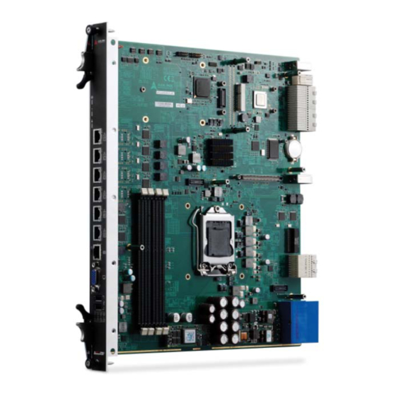
Page 11: Board Layout
2.3 Board Layout 2.3.1 aTCA-9300 Board Layout 36 37... - Page 12 CN2 (RJ-45) CN3 (RJ-45) CN4 (RJ-45) CN5 (RJ-45) CX1 (SFP) CX2 (SFP) CX3 (SFP) CX4 (SFP) U56 (GigaLan) U57 (GigaLan) U38 (GigaLan) U33 (GigaLan) U29 (GigaLan) 14 U23 (GigaLan) U52 (GigaLan) U51 (GigaLan) 17 CPU Socket (1155) PCH C216 U20 (Smart Fusion) 20 U25 (Clock Buffer) U27 (Super I/O) BATTERY...
- Page 13 OOS LED HDD LED USER LED GbE (RJ-45) Reset Button RS-232 Serial Port Hotswap LED Base and Fabric Channel LEDs...
-
Page 14: Status Led Definitions
2.3.2 Status LED Definitions The following sections describe the front panel Status LEDs: Hot-swap LED, OOS LED, BIOS/OS Boot OK LED, IPMC Payload Power Authorized LED and IPMC Chassis Identify Command LED. 2.3.2.1 Out of Service (OOS) LED Out of Service LED (Red) State Remark Blinking... - Page 15 Base and Fabric Channel LED Base Channel and Fabric Channel LED Fabric 2 Speed and Link BCH2 Speed and Link 1Gbps – OFF 100 Mbps: Green 10Gbps – Orange 1Gbps: Orange Fabric 2 ACT (Green) BCH2 ACT (Green) Blink when accessing Blink when accessing Ethernet I/O Ethernet I/O...
-
Page 16: Compliance
LEFT LED: Speed and Link 1Gbps: Amber, 100Mbps: Orange RIGHT LED: ACT Blinking while data exchanging Color: Amber 2.4 Compliance The aTCA-9300 conforms to the following specifications: PICMG 3.0 R2.0 ECN0002 AdvancedTCA PICMG 3.1 Ethernet over AdvancedTCA Option 9 NEBS Level 3 (design) -
Page 17: Functional Description
3. The Intel® Xeon® processor is ideal for thermally constrained form factors in embedded servers, communications and storage markets. Supported Processors, Maximum Power Dissipation The following table describes the Intel® Xeon® processor E5 family CPUs supported by the aTCA-9300: Name E3 1275V2 E3 1225V2... -
Page 18: Memory
3.1.2 Memory The aTCA-9300 adopts the Intel® Xeon® processor E3 (or Core™ i3) providing two memory channels supporting DDR3 800, 1066, 1333, and 1600 MT/s DIMMs. The maximum memory capacity is 32GB with memory interleaving support. The 400/533/667/800 MHz differential memory clocks are driven by the Intel®... -
Page 19: Peripherals
4.85V for the 5V line and below 3.2V for the 3.3V line. Other reset sources include the Watchdog Timer, the face plate push-button switch and also the RESET signal from the IPMC. The aTCA-9300 responds to any of these sources by initializing local peripherals. -
Page 20: Smbus Devices
3.2.2 SMBus Devices The aTCA-9300 provides a System Management Bus (SMBus) hosted by the Intel® C216. The topology is shown in the diagram below. PECI 1.1 HOST 0x56h Zon1 IPMB A_SMbus IPMB A_SMbus SMbus_Host Hot Sw ap IPMC Smart Zon3... -
Page 21: Gpio List
3.2.3 GPIO List The following table summarizes GPIO usage on the Intel® C216 Chipset Name Power Well Default Description Name Power Well Default Description Unused (PU) GPIO0 3.3V GPIO38 3.3V Unused (PU) Unused (PU) GPIO1 3.3V GPIO39 3.3V Unused (PU) USB_OC-L1(PU) GPIO2 GPIO40... -
Page 22: I/O Interfaces
480 Mb/s, 40 times faster than a full-speed USB (USB 1.1). One USB peripheral may be connected to each port. With the aTCA-R6270 (RTM), the aTCA-9300 supports two additional USB ports on the I/O panel of the RTM. -
Page 23: Vga Interface
Intel® 82576EB Gigabit Ethernet Controller are connected to Zone 2 Base Channels 1 and 2 (BCH1/BCH2). The aDB-6100-A Fabric riser card is installed on the aTCA-9300 by default and provides support for different configurations of Fabric Channels 1 and 2. Equipped with an Intel®... -
Page 24: Serial Port
Transmitted Data (TxD) Received Data (RxD) Signal Ground Signal Ground 3.3.5 Onboard CFast Interface The aTCA-9300 has one 17-pin CFast connector reserved for onboard mounting of a disk The connecotor pin list is shown as below. Signal Name JTAG_TCK JTAG_TDO JTAG_TMS... -
Page 25: Switch And Jumper Settings
3.3.6 Switch And Jumper Settings 3.3.6.1 Set Blade Operation Mode Use switch SW3 to set the Blade Operation Mode. Normal operation requires a shelf manager for the blade to boot. Standalone mode allows the blade to boot without a shelf manager. SW3 Blade Operation Pin 1 Pin 2... -
Page 26: Intelligent Platform Management System
Boards and other Intelligent FRUs. The intelligent platform management system can also perform basic recovery operations such as reset of managed entities. The IPMC controller on aTCA-9300 supports an “intelligent” hardware management system, based on the Intelligent Platform Management Interface Specification. The intelligent management system provides the ability to manage the power, cooling, and interconnect needs of intelligent devices;... - Page 27 Sensor Item Sensor Name Description Address (10) +3.3V MG (0x9) Voltage Sensor. Upper Non-Recoverable Threshold = 3.63 Volts Upper Critical Threshold = 3.564 Volts Upper Non-Critical Threshold = 3.498 Volts Lower Non-Critical Threshold = 3.102 Volts Lower Critical Threshold = 3.036 Volts Lower Non-Recoverable Threshold = 2.97 Volts (11) +12V...
-
Page 28: Sensor Reading (Fru Hotswap Sensor)
4.1.1 Sensor Reading (FRU Hotswap Sensor) Byte Data field Request data Sensor Number (FFh = reserved) Response data Completion Code Sensor Reading. [7:0] - Not used. Write as 00h. Standard IPMI byte (See “Get Sensor Reading” in IPMI specification): [7] - 0b = All Event Messages disabled from this sensor [6] - 0b = sensor scanning disabled [5] - 1b = initial update in progress. - Page 29 Byte Data field 0h = No failure. Bus enabled if no override in effect. 1h = Unable to drive clock HI 2h = Unable to drive data HI 3h = Unable to drive clock LO 4h = Unable to drive data LO 5h = Clock low timeout 6h = Under test (the IPM Controller is attempting to determine if it is causing a bus hang).
-
Page 30: Watchdog Timer Sensor
4.1.3 Watchdog Timer Sensor Sensor Type Sensor Sensor Event Type Specific Code Offset Watchdog 2 This sensor is recommended for new IPMI v1.0 and later implementations. Timer expired, status only (no action, no interrupt) Hard Reset Power Down Power Cycle 04h-07h reserved Timer interrupt... -
Page 31: Version Change Sensor
4.1.4 Version Change Sensor Sensor Type Sensor Sensor Event Type Specific Code Offset Version 00h Intelligent change detected with associated Entity. Change Informational. This offset does not imply whether the intelligent change was successful or not. Only that a change occurred. 01h Firmware or software change detected with associated Entity.Informational. -
Page 32: Get Sensor Reading Command
4.1.5 Get Sensor Reading Command Byte Data field Request data Sensor Number (FFh = reserved) Response data Completion Code Sensor reading Byte 1: byte of reading. Ignore on read if sensor does not return an numeric (analog) reading. [7] - 0b = All Event Messages disabled from this sensor [6] - 0b = sensor scanning disabled [5] - 1b = reading/state unavailable (formerly “initial update in progress”). -
Page 33: Ipmi Commands
4.2 IPMI Commands The following table presents all the commands which are supported by the aTCA-9300 in different interfaces and compatible with IPMI v1.5 and PICMG 3.0 R2.0 ECN001. There are two interfaces implemented with IPMI command support. (1) KCS: OpenIpmi; (2) IPMB0: IPMBa & IPMBb... - Page 34 HPM.1 Upgrade Commands (HPM.1) Get target upgrade capabilities ● ● Get component properties ● ● Abort Firmware Upgrade ● ● Initiate upgrade action ● ● Upload firmware block ● ● Finish firmware upload ● ● Get upgrade status ● ● Activate firmware ●...
-
Page 35: Getting Started
5 Getting Started The aTCA-9300 has been designed for easy installation. However, the following standard precautions, installation procedures, and general information must be observed to ensure proper installation and to preclude damage to the board, other system components, or injury to personnel. -
Page 36: Installing And Removing The Atca-9300
5.2 Installing and Removing the aTCA-9300 Installing the Blade 5.2.1 Follow these steps to install the aTCA-9300 blade to the chassis. Step 1 Carefully align the board edges with the chassis guide rails and push the blade inwards. - Page 37 Step 2 Check if the catch hooks and alignment pins at both ends of the module are correctly inserted into the proper openings. Push inwards on the handles until the blade is firmly seated in the chassis. (Do not force the handles if there is any abnormal resistance or it could damage the connectors and/or backplane.)
- Page 38 Step 3 Push the ejector handles inwards until it is locked.
- Page 39 Step 4 Lock both ends of the captive screws.
-
Page 40: Removing The Blade
5.2.2 Removing the Blade Follow these steps to remove the aTCA-9300 blade from the chassis. Step 1 Unlock both ends of the captive screws. - Page 41 Step 2 Pinch the lever and latch together then pull outwards to release the ejector handles at both ends. Lever Latch...
- Page 42 Step 3 Pull the blade outwards from the chassis until it is removed.
-
Page 43: Firmware Update Procedure
Step 1: Prepare an external host PC with Linux OS and connect it to the serial port on the aTCA-9300 via the COM port (USB Mini-B on the front panel). Put the IPMItool utility and new firmware image on the host PC. Enter the following command: Step 2: Enter “y”... -
Page 44: Update Over Kcs
2. Make sure the payload power is off (M1 state) before updating the IPMC firmware 5.3.2 Update over KCS Step1: Prepare an aTCA-9300 with Linux system. Enter the following command to make sure the ipmi_si and ipmi_devintf modules are loaded before the IPMItool utility can be used. -
Page 45: Update Over Lan
Step3: Select “y” and wait until the string of “firmware update procedure successful” is displayed. To update other images (BIOS, FRU, etc), just replace the target image and the file name while typing command. Item File name IPMC firmware hpm1fw.img BIOS hpm1bios.img 5.3.3... - Page 46 Step1: Prepare an external x86 PC and connect the target aTCA-9300 via BASE Interface. Put IPMItool and “target image” on the x86 PC with Linux system. Enter the following command: At the password prompt, just press "Enter" key Step2: Select “y” and wait until the string of “firmware update procedure successful”...
-
Page 47: Bios
6 BIOS 6.1 Starting the BIOS To enter the setup screen, follow these steps: 1. Power on the motherboard 2.Press the < Delete > key on your keyboard when you see the following text prompt: < Press DEL to run Setup > 3. -
Page 48: Navigation
6.1.2 Navigation The BIOS setup/utility uses a key-based navigation system called hot keys. Most of the BIOS setup utility hot keys can be used at any time during the setup navigation process. These keys include < F1 >, < F10 >, < Enter >, < ESC >, < Arrow > keys, and so on. - Page 49 There is a hot key legend located in the right frame on most setup screens. →← Left/Right. The Left and Right < Arrow > keys allow you to select a setup screen. For example: Main screen, Advanced screen, Chipset screen, and so on. ↑↓...
- Page 50 settings of the BIOS, press the < F3 > key on your keyboard. It is located on the upper row of a standard 101 keyboard. The optimized defaults settings allow the motherboard to boot up with the optimized defaults of options set. This can lessen the probability of conflicting settings.
-
Page 51: Main Setup
6.2 Main Setup When you first enter the Setup Utility, you will enter the Main setup screen. You can always return to the Main setup screen by selecting the Main tab. There are two Main Setup options. They are described in this section. The Main BIOS Setup screen is shown below. -
Page 52: System Date/System Time
6.2.2 System Date/System Time Use this option to change the system time and date. Highlight System Time or System Date using the < Arrow > keys. Enter new values using the keyboard. Press the < Tab > key or the < Arrow > keys to move between fields. The date must be entered in MM/DD/YY format. - Page 53 Active Processor Core Number of cores to enable in each processor package. Set this value to All / 1 / 2 / 3. Limit CPUID Maximum When the computer is boots, the operating system executes its CPUID instruction to identify the processor and its capabilities. Before it can do so, it must first query the processor to find out the highest input value the CPUID recognizes.
-
Page 54: Sata Configuration
6.3.2 SATA Configuration You can use this screen to select options for the SATA Configuration Settings. An example of the SATA Configuration screen is shown below. SATA Controller(s) Enable or disable SATA device. SATA Mode Selection The SATA can be configured as a legacy IDE , RAID and AHCI mode. SATA Controller Speed Indicates the maximum speed the SATA controller can support. -
Page 55: Usb Configuration
6.3.3 USB Configuration You can use this screen to select options for the USB Configuration Settings. Use the up and down < Arrow > keys to select an item. Use the < + > and < - > keys to change the value of the selected option. -
Page 56: Super Io Configuration
6.3.5 Super IO Configuration You can use this screen to select options for the Super IO settings. Use the up and down < Arrow > keys to select an item. Use the < + > and < - > keys to change the value of the selected option. -
Page 57: Serial Port Console Redirection
6.3.6 Serial Port Console Redirection You can use this screen to select options for the serial port console redirection settings. Use the up and down < Arrow > keys to select an item. Use the < + > and < - > keys to change the value of the selected option. A description of the selected item appears on the right side of the screen. - Page 58 Console Redirection Settings The settings specify how the host computer and the remote computer (which the user is using) will exchange data. Both computers should have the same or compatible settings. The screen is shown below. Terminal Typ VT100+ is the preferred terminal type for out-of-band management. Configuration options: VT100, VT100+, VT-UTF8 , ANSI.
- Page 59 Flow Control Set this option to select Flow Control for console redirection. The settings for this value are None, Hardware RTS/CTS. VT-UTF8 Combo Key Support Enabled VT-UTF8 combination key support for ANSI/VT100 terminals.. Set this value to Enable/Disable. Recorder Mode Enabled this mode, only text will be sent.
-
Page 60: Network Stack
Terminal Type VT-UTF8 is the preferred terminal type for out-of-band management. The next best choice is VT100+ and then VT100. See above, in Console Redirection Settings page, for more Help with Terminal Type/Emulation. Configuration options: VT100, VT100+, VT- UTF8 , ASNI. Bits per second Select the bits per second you want the serial port to use for console redirection. -
Page 61: Cpu Ppm Configuration
Network Stack This option is used for enabling or disabling UEFI network stack for onboard Ethernet. Ipv4 PXE Support This option is used for enable Ipv4 PXE boot support. If disabled IPV4 PXE boot option will not be created. Ipv6 PXE Support This option is used for enable Ipv6 PXE boot support. -
Page 62: Chipset Setup
Enable/Disable. CPU C6 Report Enable or disable CPU C6 (ACPI C3) report to OS. Set this value to Enable/Disable. CPU C7 Report Enable or disable CPU C7 (ACPI C3) report to OS. Set this value to Enable/Disable. 6.4 Chipset Setup Select the Chipset tab from the setup screen to enter the Chipset BIOS Setup screen. -
Page 63: Pch-Io Configuration
6.4.1 PCH-IO Configuration SB CRID It is for setting the support for PCH Compatibility Revision ID (CRID) functionality High Precision Timer The High Precision Event Timer is a hardware timer used in personal computers. A High Precision Event Timer chip consists of a 64-bit main counter counting at least at 10MHz and a set of up to 256 comparators. -
Page 64: System Agent (Sa) Configuration
6.4.2 System Agent (SA) Configuration VT-d The Intel Virtualization Technology for Directed I/O. Set this value to Enable/Disable. 6.4.2.2 Memory Configuration Memory Remap Enable or disable memory remap above 4G. Set this value to Enable / Disable. -
Page 65: Boot Setup
6.5 Boot Setup Select the Boot tab from the setup screen to enter the Boot BIOS Setup screen. You can select any of the items in the left frame of the screen, such as Boot Device Priority, to go to the sub menu for that item. You can display an Boot BIOS Setup option by highlighting it using the <... -
Page 66: Csm Parameter
Option ROM Messages Set this option to enable for allowing system to display PCI devices’ option ROMs during system boot up. INT19 Trap Response Interrupt 19 is the software interrupt that handles the boot disk function. When set to Enabled, this item allows the option ROMs to trap interrupt 19. Set Boot Priority Set Boot Option #1 ~2 boot priority. -
Page 67: Security Setup
Launch PXE OpROM policy This option controls the execution of UEFI and Legacy PXE OpROM. Set this value to Do not launch / Legacy only. Launch Storage OpROM policy This option controls the execution of UEFI and Legacy Storage OpROM. Set this value to Do not launch / UEFI only / Legacy only. -
Page 68: Save & Exit Menu
6.7 Save & Exit Menu Select the Exit tab from the setup screen to enter the Exit BIOS Setup screen. You can display an Exit BIOS Setup option by highlighting it using the < Arrow > keys. The Exit BIOS Setup screen is shown below. Save Changes and Reset Reset the system after saving the changes. - Page 69 Discard Changes Discard Changes done so far to any of the setup options. Restore Defaults Restore/Load Defaults values for all the setup options. Save as User Defaults Save the changes done so far as user defaults. Restore User Defaults Restore the user defaults to all the setup options.
-
Page 70: Server Mgmt Setup Screen
6.8 Server Mgmt Setup Screen You can use this screen to specify options for the Server Management settings. Use the up and down <Arrow> keys to select an item. Use <+> and <-> keys to change the value of the selected option. The settings are described in the following pages. The screen is shown as below. -
Page 71: Serial Over Lan
Users can use the SOL feature to transmit/receive serial console message from a remote site with full console management functionality. The aTCA-9300 supports 1 channel (channel 5) and 2 user IDs for SOL. You can refer to the following sections for more detailed information. -
Page 72: Configure The Target Atca-9300
Build the source code and install IPMItool: make make install Now your remote client is ready to connect to the target the aTCA-9300. Note: The install must be run with root permissions to overlay the existing IPMItool utility in /usr/local/bin. -
Page 73: Linux System Setting
Add the following line to the init configuration file /etc/inittab. s1:12345:respawn:/sbin/agetty –L ttyS1 115200 vt100 Now the target aTCA-9300 is ready for SOL connection. 7.4 Establish SOL Connection Execute the following command from your remote client to establish the SOL Connection Command: ipmitool -I lanplus -H <Target IPMC IP >... - Page 74 The default values of the aTCA-9300 SOL parameters are listed in the table below Parameter Default Value Channel 5 IP Address 172.17.172.134 User ID User Name adlinkuser Password adlinkuser Below are 2 samples to establish the SOL session via channel 5 with default user name and...
-
Page 75: Drivers
8 Drivers The drivers for aTCA-9300 are available on the ADLINK website. Please visit the aTCA-9300 product web site for more details: http://www.adlinktech.com/PD/web/PD_detail.php?cKind=&pid=1111 We recommend using all the drivers provided on the ADLINK website to ensure driver compatibility. Contact ADLINK to get support for other operating system.. -
Page 76: Safety Instructions
Safety Instructions 1. Please read these safety instructions carefully. 2. Please keep this User‘s Manual for later reference. 3. One AC Inlets provided and service as Disconnect Devices, disconnect the equipment from both AC outlets use these AC Inlets before servicing or clearing. Use moisture sheet or cloth for cleaning. -
Page 77: Getting Service
5215 Hellyer Avenue, #110, San Jose, CA 95138, USA Tel: +1-408-360-0200 Toll Free: +1-800-966-5200 (USA only) Fax: +1-408-360-0222 Email: info@adlinktech.com ADLINK Technology (China) Co., Ltd. Address: 上海市浦东新区张江高科技园区芳春路 300 号 (201203) 300 Fang Chun Rd., Zhangjiang Hi-Tech Park, Pudong New Area, Shanghai, 201203 China Tel: +86-21-5132-8988 Fax: +86-21-5132-3588 Email: market@adlinktech.com... - Page 78 84 Genting Lane #07-02A, Cityneon Design Centre, Singapore 349584 Tel: +65-6844-2261 Fax: +65-6844-2263 Email: singapore@adlinktech.com ADLINK Technology Singapore Pte. Ltd. (Indian Liaison Office) Address: 1st Floor, #50-56 (Between 16th/17th Cross) Margosa Plaza, Margosa Main Road, Malleswaram, Bangalore-560055, India Tel: +91-80-65605817, +91-80-42246107 Fax: +91-80-23464606 Email: india@adlinktech.com...
Need help?
Do you have a question about the aTCA-9300 and is the answer not in the manual?
Questions and answers