
Related Manuals for AB Sciex 4500 Series


Summary of Contents for AB Sciex 4500 Series
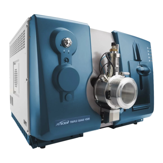
- Page 1 AB SCIEX 4500 Series of Instruments System User Guide Document Number: D5030863 A Release Date: March 2012...
- Page 2 This document is provided to customers who have purchased AB Sciex equipment to use in the operation of such AB Sciex equipment. This document is copyright protected and any reproduction of this document or any part of this document is strictly prohibited, except as AB Sciex may authorize in writing.
-
Page 3: Table Of Contents
Installed Project Folders ......... . .37 System User Guide 4500 Series of Instruments Document Number: D5030863 A... - Page 4 Generate XWCs ..........77 4500 Series of Instruments...
- Page 5 Consumables ..........123 System User Guide 4500 Series of Instruments Document Number: D5030863 A...
- Page 6 Contents Appendix B 4500 Series Instrument Requirements and Parameters ..125 Electrical and Gas Requirements ........125 Instrument Parameters .
-
Page 7: Chapter 1 Foreword
Read the warning and follow all precautions before performing any operation described in the guide. Failure to do so can result in serious injury. System User Guide 4500 Series of Instruments Document Number: D5030863 A 7 of 142... -
Page 8: Qualified Personnel
Checklist to train the customer on system operation, cleaning, and basic maintenance. Only qualified AB SCIEX personnel shall install and service the equipment. Only personnel qualified by AB SCIEX shall operate and maintain the equipment. Contact an AB SCIEX FSE for more information. -
Page 9: Shipping Labels
Australia and New Zealand • Electromagnetic Interference—AS/NZ CISPR 11 (Class A) • Safety—AS/NZ 61010-1 Canada • Electromagnetic Interference—CAN/CSA CISPR11. This ISM device complies with Canadian ICES-001. System User Guide 4500 Series of Instruments Document Number: D5030863 A 9 of 142... -
Page 10: Europe
Table 1-2 Labels on the Mass Spectrometer External Labels Definition WARNING: NO USER SERVICEABLE PARTS INSIDE. REFER SERVICING TO QUALIFIED PERSONNEL. EN61326—1:2006 CLASS A, GROUP 1, ISM EQUIPMENT 4500 Series of Instruments System User Guide 10 of 142 Document Number: D5030863 A... - Page 11 Caution, see accompanying documents. Minimum of 6 persons required to safely lift this equipment WARNING: Hot Surface Hazard. Operator Guide Follow operating instructions (mandatory) Alternating Current Amperes (current) System User Guide 4500 Series of Instruments Document Number: D5030863 A 11 of 142...
-
Page 12: Occupational Health And Safety Symbols
This section describes some occupational health and safety symbols found in the laboratory environment. Table 1-3 Chemical Hazard Symbols Safety Symbol Description Biohazard Corrosive or Caustic Chemical Hazard Explosion Hazard Oxidizing Chemical Hazard Poison Hazard Reactive Chemical Hazard 4500 Series of Instruments System User Guide 12 of 142 Document Number: D5030863 A... - Page 13 Fire Hazard Hot Surface Hazard Laser Radiation Hazard Lifting Hazard Magnetic Hazard Puncture Hazard Table 1-5 Pressurized Gas Hazard Warning Symbols Safety Symbol Description Pressurized Gas Hazard System User Guide 4500 Series of Instruments Document Number: D5030863 A 13 of 142...
-
Page 14: Mains Supply
60 Hz) at 230 VAC. An external line transformer is not needed for the instrument, optional bench, or roughing pump. Caution: Do not unpack or connect any components. The AB SCIEX FSE will unpack, connect, and configure the system for the proper operating voltage. -
Page 15: Instrument Disposal (Waste Electrical And Electronic Equipment)
WEEE (waste, electrical, and electronic equipment). To make sure that you safely dispose of this equipment, contact an FSE for instructions. European Union customers: Contact a local AB SCIEX Customer Service office for complimentary equipment pick-up and recycling. - Page 16 Foreword 4500 Series of Instruments System User Guide 16 of 142 Document Number: D5030863 A...
-
Page 17: Chapter 2 System Information
The 4500 series of instruments have a series of quadrupole filters that transmit ions according to their mass-to-charge (m/z) value. The first quadrupole in this series is the QJet Ion Guide located between the orifice plate and Q0. - Page 18 Figure 2-2 Rear and Side Views on page 19 shows the location of the instrument connections, including the locations of the reset and vent buttons and the instrument switch. 4500 Series of Instruments System User Guide 18 of 142 Document Number: D5030863 A...
- Page 19 System Information Figure 2-2 Rear and Side Views Item Description For more information... Roughing pump vacuum connection Contact an AB SCIEX FSE. Nitrogen gas supply (Curtain Gas™ Contact an AB SCIEX FSE. supply, CAD gas) Source exhaust supply Contact an AB SCIEX FSE.
-
Page 20: Instrument Panel Symbols
System Information Figure 2-2 Rear and Side Views (Continued) Item Description For more information... Air supply (Gas1/Gas2) Contact an AB SCIEX FSE. Instrument Panel Symbols Table 2-1 shows the instrument status LEDs. Table 2-1 Instrument Panel Symbols Instrument LEDs Color... -
Page 21: Reset The System
9. Unplug the mains supply cable from the bulkhead on the left side of the instrument. 10. Unplug the roughing pump mains supply cable from the electrical mains supply. System User Guide 4500 Series of Instruments Document Number: D5030863 A 21 of 142... -
Page 22: Edit The Hardware Profile For The Integrated Syringe Pump
Figure 2-4 Lowering the syringe. Make sure that the end of the syringe is flush against the base and that the shaft of the syringe rests in the cutout. 4500 Series of Instruments System User Guide 22 of 142 Document Number: D5030863 A... - Page 23 Figure 2-5 Safety stop Item Description Automatic syringe stop. After the post hits the automatic syringe stop, the syringe pump stops. System User Guide 4500 Series of Instruments Document Number: D5030863 A 23 of 142...
- Page 24 The light next to the button illuminates when the syringe pump is in use. Tip! The syringe pump can also be started using the Analyst software in Manual Tuning mode. 4500 Series of Instruments System User Guide 24 of 142 Document Number: D5030863 A...
-
Page 25: Configure The Integrated Syringe Pump
1. In the Navigation bar, under Configure, double-click Hardware Configuration. 2. Create or edit the hardware profile containing the instrument. 3. In the Configuration tab (Figure 2-8 Configuration tab), select Use integrated injector/diverter valve. System User Guide 4500 Series of Instruments Document Number: D5030863 A 25 of 142... -
Page 26: Plumb The Diverter Valve
The diverter valve is a two position, 6 port valve. If you put the valve in Position A (Figure 2-9), the sample flows through the external loop. When you switch the valve to Position B (Figure 2-10), the sample is injected. 4500 Series of Instruments System User Guide 26 of 142 Document Number: D5030863 A... - Page 27 System Information Figure 2-9 Diverter valve—injector mode position A Item Description Sample in Waste out Sample loop Mobile phase in To column System User Guide 4500 Series of Instruments Document Number: D5030863 A 27 of 142...
- Page 28 System Information Figure 2-10 Diverter valve—injector mode position B Item Sample in Sample in Waste out Sample loop Mobile phase in To column 4500 Series of Instruments System User Guide 28 of 142 Document Number: D5030863 A...
-
Page 29: Plumb The Diverter Valve In Diverter Mode
System Information Plumb the Diverter Valve in Diverter Mode Figure 2-11 Diverter valve—diverter mode position A Item Description Sample in Waste out To column System User Guide 4500 Series of Instruments Document Number: D5030863 A 29 of 142... -
Page 30: Instrument Safe Fluids
• Ammonium acetate (0 to 1%) Note: This list is not complete. Do not use any other fluid until confirmation is received from AB SCIEX that it will not present a hazard. 4500 Series of Instruments System User Guide 30 of 142... -
Page 31: Chapter 3 Hardware Profiles And Projects
1. In the Navigation Bar, under Configure, double-click Hardware Configuration. Figure 3-1 Hardware Configuration Editor dialog 2. In the Hardware Configuration Editor dialog, click New Profile. System User Guide 4500 Series of Instruments Document Number: D5030863 A 31 of 142... - Page 32 3. In the Profile Name field, type a name. 4. Click Add Device. In the Available Devices dialog, in the Device Type field, Mass Spectrometer is the preset value. 4500 Series of Instruments System User Guide 32 of 142 Document Number: D5030863 A...
- Page 33 A hardware profile does not have to be deactivated before activating another. Click a hardware profile and then click Activate Profile. The other profile is deactivated automatically. 16. Click Close. System User Guide 4500 Series of Instruments Document Number: D5030863 A 33 of 142...
-
Page 34: Add Devices To A Hardware Profile
If the device uses Ethernet as a communication interface, type the IP address assigned to the device by the administrator or use the corresponding host name for the address. 4500 Series of Instruments System User Guide 34 of 142 Document Number: D5030863 A... -
Page 35: Troubleshooting Hardware Profile Activation
Wait until all device power-up activities are complete before trying to activate the hardware profile again. Some devices may require 30 seconds or more to complete the power-up activities. 8. Activate the hardware profile. System User Guide 4500 Series of Instruments Document Number: D5030863 A 35 of 142... -
Page 36: Create Projects And Subprojects
5. To use this project and subproject folder organization for all new projects, select the Set configuration as default for new projects check box. All new projects are created with this folder configuration. 6. Click OK. 4500 Series of Instruments System User Guide 36 of 142 Document Number: D5030863 A... -
Page 37: Create A Subproject
API Instrument folder in the Tuning Cache folder and named with the date and time they were created. The Tuning Cache is automatically cleared periodically. System User Guide 4500 Series of Instruments Document Number: D5030863 A 37 of 142... -
Page 38: Back Up The Api Instrument Folder
Subprojects can be copied only from another project that has existing subprojects. If the same folders exist at both the project and subproject levels, the software uses the project level folders. 4500 Series of Instruments System User Guide 38 of 142... -
Page 39: Chapter 4 Instrument Tuning And Calibrating
Required material • Tuning solutions that are supplied in the Standards Chemical Kit shipped with the system. If needed, a new Kit can be ordered from AB SCIEX. • 5 ml, 1 ml, and 250 µl serial gas-tight syringes. •... -
Page 40: Verify Or Adjust Performance
The Results Summary is saved as a document in the folder indicated at the top of the report. Users can print the Results Summary or open a previously saved Results Summary. 4500 Series of Instruments System User Guide 40 of 142... - Page 41 Instrument Tuning and Calibrating Figure 4-1 Results Summary System User Guide 4500 Series of Instruments Document Number: D5030863 A 41 of 142...
- Page 42 Instrument Tuning and Calibrating 4500 Series of Instruments System User Guide 42 of 142 Document Number: D5030863 A...
-
Page 43: Chapter 5 Basic Acquisition Methods
Add a Period • In the Acquisition method pane, right-click the Mass Spec icon, and then click Add period. A period is added below the last period created. System User Guide 4500 Series of Instruments Document Number: D5030863 A 43 of 142... -
Page 44: Copy An Experiment Into A Period
Q3 Multiple Ions (Q3 MI): A zero width scan type using the third quadrupole (Q3). The ion intensity is returned for the specified masses only. 4500 Series of Instruments System User Guide 44 of 142... -
Page 45: Lit-Mode Scan Types
As with any in-trap CID technique, there is a low mass cut-off for the second MS/MS step due to the condition that the lowest mass fragment and precursor System User Guide 4500 Series of Instruments Document Number: D5030863 A 45 of 142... -
Page 46: About Spectral Data Acquisition
The nature of the spectra aids in the interpretation of the structure and fragmentation pathways of the molecule of interest. This scan type is not applicable to the AB SCIEX 4500 QTRAP and AB SCIEX 5500 QTRAP systems. About Spectral Data Acquisition Spectral data can be acquired in one of three modes, as shown in the following table. - Page 47 NanoSpray ion source and interface are installed. Source and The sdp parameter controls the selection of the DuoSpray™ ion source probes: TurboIonSpray probe or APCI probe System User Guide 4500 Series of Instruments Document Number: D5030863 A 47 of 142...
- Page 48 GS1 (Gas 1) Source and The GS1 parameter controls the nebulizer gas. The nebulizer gas helps generate small droplets of sample flow and affects spray stability and sensitivity. 4500 Series of Instruments System User Guide 48 of 142 Document Number: D5030863 A...
- Page 49 Either select or clear the feature based on the experiment. The recommended fixed fill time to use with Q0 trapping is 20 ms or greater. System User Guide 4500 Series of Instruments Document Number: D5030863 A 49 of 142...
- Page 50 (MS3) experiment when CES is used. By typing a collision energy spread value, CES is automatically turned on. Use the preset value and optimize for the compound. 4500 Series of Instruments System User Guide 50 of 142 Document Number: D5030863 A...
- Page 51 The Q3 Cool Time parameter controls the amount of time that the precursor ions are allowed to cool prior to collection of their product ions. Use the preset value. System User Guide 4500 Series of Instruments Document Number: D5030863 A 51 of 142...
- Page 52 LIT scan speeds. CEM (CEM) Detector The CEM parameter controls the voltage applied to the detector. The voltage controls the detector response. 4500 Series of Instruments System User Guide 52 of 142 Document Number: D5030863 A...
-
Page 53: Acquisition Method Editor Icons
DAD, refer to Show DAD Data on page Opens the ADC Properties tab. For more information about the ADC, refer to Show ADC Data on page System User Guide 4500 Series of Instruments Document Number: D5030863 A 53 of 142... - Page 54 Basic Acquisition Methods 4500 Series of Instruments System User Guide 54 of 142 Document Number: D5030863 A...
-
Page 55: Chapter 6 Batches
5. If an LC method is used, then before the run is started, make sure that there is enough solvent in the reservoirs for the primary flow rate for all of the sample runs and the maximum idle time. System User Guide 4500 Series of Instruments Document Number: D5030863 A 55 of 142... -
Page 56: Create And Submit A Batch
1. In the Navigation Bar, under Acquire, double-click Build Acquisition Batch. Figure 6-2 Batch Editor 2. In the Sample tab, in the Set list, type a name. 3. Click Add Set. 4. Click Add Samples. 4500 Series of Instruments System User Guide 56 of 142 Document Number: D5030863 A... - Page 57 12. In the New samples section, in the Number field, type the number of new samples. 13. Click OK. The sample table fills with the sample names and data file names. System User Guide 4500 Series of Instruments Document Number: D5030863 A 57 of 142...
-
Page 58: Change Sample Order
Standby, sample acquisition will start automatically. 1. In the Navigation Bar, click Acquire. 2. Click View > Sample Queue. 4500 Series of Instruments System User Guide 58 of 142 Document Number: D5030863 A... -
Page 59: Set Sample Locations In The Batch Editor
In the Vial Position column, type the position of the vial in the plate or tray. 3. Save the file. Select Vial Positions using the Locations Tab 1. In the Batch Editor, click the Locations tab. System User Guide 4500 Series of Instruments Document Number: D5030863 A 59 of 142... - Page 60 To perform multiple injections from the same vial, hold down the Ctrl key and then click the vial location. The red circle changes to a green circle. 4500 Series of Instruments System User Guide 60 of 142...
-
Page 61: Stop Sample Acquisition
To select more than one well or vial hold down the Shift key and then click the first and last at a time well or vial in the range. System User Guide 4500 Series of Instruments Document Number: D5030863 A 61 of 142... -
Page 62: Batch Editor Right-Click Menu
Queue States and Device Status The Queue Manager shows queue, batch, and sample status. Detailed information about a particular sample in the queue can also be viewed. 4500 Series of Instruments System User Guide 62 of 142 Document Number: D5030863 A... -
Page 63: Queue States
Waiting In the Waiting state, the system will automatically begin acquisition when the next sample is submitted. System User Guide 4500 Series of Instruments Document Number: D5030863 A 63 of 142... -
Page 64: View Instrument And Device Status Icons
The device is waiting for a command from the software, from another device, or for some action by the operator. Running Green The device is running. 4500 Series of Instruments System User Guide 64 of 142 Document Number: D5030863 A... -
Page 65: Queue Right-Click Menu
Opens the Sample Details dialog. Reacquire Acquires a sample again. Insert Pause Inserts a pause, in seconds, between two samples. Delete Deletes either the batch or the selected samples. System User Guide 4500 Series of Instruments Document Number: D5030863 A 65 of 142... - Page 66 Next Period Starts a new period. Extend Period Extends the current period. Next Sample Stops acquiring the current sample and to start acquiring the next sample. 4500 Series of Instruments System User Guide 66 of 142 Document Number: D5030863 A...
- Page 67 Ready Puts the instrument in Ready mode. Reserve Instrument for Reserves the instrument for tuning and calibrating. Tuning IDA Method Wizard Starts the IDA Method Wizard. System User Guide 4500 Series of Instruments Document Number: D5030863 A 67 of 142...
- Page 68 Batches 4500 Series of Instruments System User Guide 68 of 142 Document Number: D5030863 A...
-
Page 69: Chapter 7 Analyzing And Processing Data
1. In the Navigation Bar, under Explore, double-click Open Data File. 2. In the Data Files list, double-click Triple Quad. 3. Select QuanData.wiff. System User Guide 4500 Series of Instruments Document Number: D5030863 A 69 of 142... -
Page 70: Show Experimental Conditions
Show Data in Tables • With a data file open, click Explore > Show > Show List Data. The data is shown in a pane below the graph. 4500 Series of Instruments System User Guide 70 of 142 Document Number: D5030863 A... - Page 71 Opens the Analyst Classic dialog. Parameters IntelliQuan Parameters Opens the Intelliquan dialog. Save As Text Saves the data as text file. Delete Pane Deletes the pane. System User Guide 4500 Series of Instruments Document Number: D5030863 A 71 of 142...
-
Page 72: Show Adc Data
Analyst Classic Parameters or Intelliquan Parameters, which ever is active. 3. To remove the colored peaks, right-click in the Peak List tab and then clear Show Peaks in Graph. 4500 Series of Instruments System User Guide 72 of 142 Document Number: D5030863 A... -
Page 73: Chromatograms
4. Click Explore > Show > Show TIC. The TIC opens in a new pane. Tip! Right-click inside a pane containing a spectrum and then click Show TIC. System User Guide 4500 Series of Instruments Document Number: D5030863 A 73 of 142... -
Page 74: Show A Spectrum From A Tic
The specified masses method extracts ions from any type of spectrum or chromatogram. Select up to ten start and stop masses for which to generate XICs. 4500 Series of Instruments System User Guide 74 of 142 Document Number: D5030863 A... - Page 75 To extract ions by selecting masses 1. Open a spectrum or chromatogram. 2. Click Explore > Extract Ions > Use Dialog. System User Guide 4500 Series of Instruments Document Number: D5030863 A 75 of 142...
-
Page 76: Generate Bpcs
The selection is highlighted in blue. 2. Click Explore > Show > Show Base Peak Chromatogram. The selections are shown in the Start Time and End Time fields. 4500 Series of Instruments System User Guide 76 of 142 Document Number: D5030863 A... -
Page 77: Generate Xwcs
Table 7-8 Graph Options on page 1. Open a data file that contains a DAD spectrum. 2. Anywhere in the pane, right-click and then click Extract Wavelengths. System User Guide 4500 Series of Instruments Document Number: D5030863 A 77 of 142... -
Page 78: Show Dad Data
2. Click Explore > Show > Show DAD TWC. The TWC opens in a pane below the DAD spectrum. Tip! Right-click inside the pane containing the DAD spectrum and then click Show DAD TWC. 4500 Series of Instruments System User Guide 78 of 142 Document Number: D5030863 A... -
Page 79: Adjust The Threshold
Add Caption Adds a caption at the cursor point in the pane. Add User Text Adds a text box at the position of the mouse cursor. System User Guide 4500 Series of Instruments Document Number: D5030863 A 79 of 142... -
Page 80: Data Processing
The user can zoom in on part of a graph to view a particular peak or an area in greater detail in both spectra and chromatograms. The user can also zoom in repeatedly to view smaller peaks. 4500 Series of Instruments System User Guide... -
Page 81: Graphs
Link panes 1. With the two graphs open, click one to make that pane active. 2. Click Explore > Link and then click the other pane. System User Guide 4500 Series of Instruments Document Number: D5030863 A 81 of 142... -
Page 82: Zoom In On The Y-Axis
Tip! To return the graph to the original scale, double-click on either axis. To restore the entire graph to original scale, click Explore > Home Graph. 4500 Series of Instruments System User Guide 82 of 142 Document Number: D5030863 A... - Page 83 View ADC data. Show File Info Shows the experimental conditions used to collect the data. Add arrows Add arrows to the x-axis of the active graph. System User Guide 4500 Series of Instruments Document Number: D5030863 A 83 of 142...
- Page 84 Generates a TWC of the DAD. Show DAD Generates a DAD. Extract Wavelength Extracts up to three wavelength ranges from a DAD spectrum to view the XWC. 4500 Series of Instruments System User Guide 84 of 142 Document Number: D5030863 A...
-
Page 85: Chapter 8 Analyzing And Processing Quantitative Data
Alternatively, an existing quantitation method can be used to quantitate different sets of data. This is the most common way of creating a quantitation method. System User Guide 4500 Series of Instruments Document Number: D5030863 A 85 of 142... -
Page 86: About Results Tables
Internal Standards table, when a value in the Q1/Q3 field is selected, the Name field is automatically populated. 6. In the Analytes table, do the following: 4500 Series of Instruments System User Guide 86 of 142 Document Number: D5030863 A... -
Page 87: Create A Results Table Using The Quantitation Wizard
The Create Quantitation Set - Select Settings & Query page opens. 6. In the Default Query section, click Select Existing: Query. 7. In the Query list, select Accuracy 15%. 8. Click Next. System User Guide 4500 Series of Instruments Document Number: D5030863 A 87 of 142... -
Page 88: Create A Standard Query
3. Click Next. 4. In the Select Settings & Query page, in the Default Query section, select Create New Standard Query. 5. Type a query name. 4500 Series of Instruments System User Guide 88 of 142 Document Number: D5030863 A... - Page 89 Concentration column. 8. In the Maximum Allowed Accuracy Variation for Standards (%) table, in the Max. Variation column, type the maximum allowable percent of variation for each System User Guide 4500 Series of Instruments Document Number: D5030863 A 89 of 142...
-
Page 90: Results Table Right-Click Menu
To return to the full view, right-click and then click Full. Results Table Right-Click Menu Right-click in the Results Table table to access the following options. 4500 Series of Instruments System User Guide 90 of 142 Document Number: D5030863 A... -
Page 91: Peak Review And Manual Integration Of Peaks
After identifying the analytes and internal standards that the software must find, the software searches for the peaks in the samples. When the software identifies a peak, it shows the System User Guide 4500 Series of Instruments Document Number: D5030863 A 91 of 142... -
Page 92: Review Peaks
1 and Num. columns to 2. 6. In the Automatic Zooming section, click Zoom Y axis to: 100% of largest peak to show the entire peak. 4500 Series of Instruments System User Guide 92 of 142 Document Number: D5030863 A... - Page 93 In this example, the peak can be integrated closer to the baseline by selecting the Specify Parameters option. Tip! To move to a specific peak in the Peak Review pane, select the corresponding row in the Results Table. System User Guide 4500 Series of Instruments Document Number: D5030863 A 93 of 142...
- Page 94 15. To update the algorithm for all peaks, right-click in the pane and then click Update Method. Note: The Update Method function only updates the algorithm values for that specific analyte (or internal standard) and not all analytes. 4500 Series of Instruments System User Guide 94 of 142 Document Number: D5030863 A...
-
Page 95: Manually Integrate Peaks
Table, as are the peaks that have algorithm parameter changes for a sample but not updated to the entire analyte group. 1. In the Peak Review pane, click Manual Integration Mode. System User Guide 4500 Series of Instruments Document Number: D5030863 A 95 of 142... -
Page 96: Peak Review Right-Click Menu
If a peak was correct as originally selected, right-click the peak and then click Revert to Method. Peak Review Right-Click Menu Right-click in the Peak Review window or pane to access the following options. 4500 Series of Instruments System User Guide 96 of 142 Document Number: D5030863 A... -
Page 97: Calibration Curves
The area or height ratio of a sample is then applied to this curve to find the concentration System User Guide 4500 Series of Instruments Document Number: D5030863 A 97 of 142... -
Page 98: View Calibration Curves
4. If required, repeat these steps to create a more appropriate curve. 5. To save the changes, click Accept. 4500 Series of Instruments System User Guide 98 of 142 Document Number: D5030863 A... -
Page 99: Overlay Calibration Curves
The software plots the curves for all selected tables on the same graph. Calibration Curve Right-Click Menu Right-click in the Calibration window or pane table to access the following options. System User Guide 4500 Series of Instruments Document Number: D5030863 A 99 of 142... -
Page 100: Sample Statistics
The %CV shows the coefficient of variance between the measurements of a single parameter, for example the area. Accuracy shows how close the plotted point is to the interperlated value. 4500 Series of Instruments System User Guide 100 of 142... -
Page 101: Compare Results Between Batches
Show Active Graph Shows the analyte chromatogram only. Show Both Analyte and IS Shows the analyte and its associated chromatogram (available only when an associated internal standard exists). System User Guide 4500 Series of Instruments Document Number: D5030863 A 101 of 142... - Page 102 Peak Review - Window Opens peaks in a window. Calibration - Pane Opens the calibration curve in a pane. Calibration - Window Opens the calibration curve in a window. 4500 Series of Instruments System User Guide 102 of 142 Document Number: D5030863 A...
- Page 103 Shows the audit trail for the Results Table. Clear Audit Trail Clears the audit trail for the Results Table. Statistics Opens the Statistics window. Report Generator Opens the Reporter software. System User Guide 4500 Series of Instruments Document Number: D5030863 A 103 of 142...
- Page 104 Analyzing and Processing Quantitative Data 4500 Series of Instruments System User Guide 104 of 142 Document Number: D5030863 A...
-
Page 105: Appendix A Turbo V™ Ion Source User Reference
Introduction to the Ion Source Figure A-1 shows the parts of the ion source. Figure A-1 Ion source components Item Description Sample tubing System User Guide 4500 Series of Instruments Document Number: D5030863 A 105 of 142... -
Page 106: Probes
At higher flow rates, ionization efficiency increases, resulting in improved sensitivity. Compounds with extremely high polarity and low surface activity usually show the greatest sensitivity increases. The TurboIonSpray 4500 Series of Instruments System User Guide 106 of 142... - Page 107 Buffers are readily tolerated by the ion source without significant contamination and the flash vaporization of the sprayed effluent allows up to 100% water to be used without difficulty. System User Guide 4500 Series of Instruments Document Number: D5030863 A 107 of 142...
-
Page 108: Gas And Electrical Connections
For more information on the requirements for the source exhaust system, refer to the Site Planning Guide for the mass spectrometer. 4500 Series of Instruments System User Guide 108 of 142... -
Page 109: Installation
WARNING! Electrical Shock Hazard: Make sure that the ion source housing is completely disconnected from the mass spectrometer before proceeding. System User Guide 4500 Series of Instruments Document Number: D5030863 A 109 of 142... - Page 110 WARNING! Electrical Shock Hazard: Do not bypass the grounding union connection. The grounding union provides safety grounding between the mass spectrometer and the sample introduction device. 4500 Series of Instruments System User Guide 110 of 142 Document Number: D5030863 A...
-
Page 111: Optimization
For multiply-charged proteins and peptides introduced at a few microliters per minute, position the sprayer nozzle higher than the curtain plate orifice. System User Guide 4500 Series of Instruments Document Number: D5030863 A 111 of 142... - Page 112 Source Gas 1 (GS1). Typical values are between 40 psi and 60 psi for GS1. 2. Type a starting value for Ion Source Gas 2 (GS2). 4500 Series of Instruments System User Guide 112 of 142 Document Number: D5030863 A...
- Page 113 Prevent contamination of the orifice • Prevent piercing of the Curtain Gas flow, which can create an unstable signal • Prevent electrical shorting due to the presence of the liquid System User Guide 4500 Series of Instruments Document Number: D5030863 A 113 of 142...
-
Page 114: Optimize The Apci Probe
WARNING! Electrical Shock Hazard: Follow this procedure to avoid contact with the high voltages applied to the corona discharge needle and the curtain plate. 1. Use the slotted screwdriver to rotate the plastic screw on the top of the needle. 4500 Series of Instruments System User Guide 114 of 142... - Page 115 1 µA and 5 µA in positive mode. If there are no changes in signal when increasing the current, then leave the current at the lowest value that provides the best signal or signal-to-noise ratio. System User Guide 4500 Series of Instruments Document Number: D5030863 A 115 of 142...
-
Page 116: Maintenance
Flush the ion source periodically, regardless of the type of compounds sampled. Do this by setting up a method in the Analyst software specifically for performing a flushing operation. 1. Switch to a mobile phase that is 50:50 water:acetonitrile or 50:50 water:methanol. 4500 Series of Instruments System User Guide 116 of 142... -
Page 117: Remove The Ion Source
4. Gently pull the probe straight up out of the tower. Do not let the tip of the probe touch anything during removal or storage. 5. Put the probe on a secure, clean surface. System User Guide 4500 Series of Instruments Document Number: D5030863 A 117 of 142... -
Page 118: Clean The Electrode Tube
4. Pull the PEEK union and the attached electrode tube from the probe. Refer to Figure A-4. 5. Use the 1/4 inch open-ended wrench to remove the retaining nut that holds the electrode tube in the PEEK union. 4500 Series of Instruments System User Guide 118 of 142 Document Number: D5030863 A... -
Page 119: Adjust The Electrode Tip Extension
Adjust the black electrode adjustment nut on the top of the probe to extend or retract the electrode tip. The electrode tip should extend between 0.5 mm and 1.0 mm from the end of the probe as shown in Figure A-5. System User Guide 4500 Series of Instruments Document Number: D5030863 A 119 of 142... -
Page 120: Replace The Corona Discharge Needle
1. Remove the ion source and probe from the mass spectrometer, refer to Remove the Ion Source on page 117 Remove the Probe on page 117. 4500 Series of Instruments System User Guide 120 of 142 Document Number: D5030863 A... -
Page 121: Replace The Sample Tubing
2. Remove the ion source. Refer to Remove the Ion Source on page 117. 3. Disconnect the sample tubing from the probe and the union. System User Guide 4500 Series of Instruments Document Number: D5030863 A 121 of 142... -
Page 122: Troubleshooting
FSE. Background noise is high. Temperature (TEM) is too Optimize the temperature. high. Heater gas flow rate (GS2) is Optimize heater gas flow. too high. 4500 Series of Instruments System User Guide 122 of 142 Document Number: D5030863 A... -
Page 123: Consumables
027950 FRU*KIT ELECTRODE NEB APCI electrode kit 1003263 FUSE*4A 250v 5X20 LONG F3 fuse T4A 250 V, 5 mm × 20 mm time DELAY delay (Not used for AB SCIEX ™ TripleTOF 5600 systems.) Table A-7 Part # Description Quantity Details... - Page 124 Turbo V™ Ion Source User Reference 4500 Series of Instruments System User Guide 124 of 142 Document Number: D5030863 A...
-
Page 125: Appendix B 4500 Series Instrument Requirements And Parameters
55 psi. Instrument Parameters The following table contains generic parameters for the 4500 series of instruments. The first number under each scan type is the preset value; the range of numbers is the accessible range for each parameter. - Page 126 (4)DuoSpray™ ion source, 1=TIS, and 2=HN (5)PhotoSpray ion source (6) NanoSpray ® ion source (a) AB SCIEX QTRAP 4500 system (b) AB SCIEX Triple Quad™ 4500 system 4500 Series of Instruments System User Guide 126 of 142 Document Number: D5030863 A...
- Page 127 (4)DuoSpray™ ion source, 1=TIS, and 2=HN (5)PhotoSpray ion source (6) NanoSpray ® ion source (a) AB SCIEX QTRAP 4500 system (b) AB SCIEX Triple Quad™ 4500 system System User Guide 4500 Series of Instruments Document Number: D5030863 A 127 of 142...
- Page 128 (4)DuoSpray™ ion source, 1=TIS, and 2=HN (5)PhotoSpray ion source (6) NanoSpray ® ion source (a) AB SCIEX QTRAP 4500 system (b) AB SCIEX Triple Quad™ 4500 system Table B-4 QTRAP 4500 System Parameters for LIT Scan Types Only Access ID Positive Ion Mode...
- Page 129 4500 Series Instrument Requirements and Parameters Table B-4 QTRAP 4500 System Parameters for LIT Scan Types Only (Continued) Access ID Positive Ion Mode Negative Ion Mode High High Low; Medium; High Low; Medium; High (1)(2) 5500 -4500 0 to 5500...
- Page 130 4500 Series Instrument Requirements and Parameters Table B-4 QTRAP 4500 System Parameters for LIT Scan Types Only (Continued) Access ID Positive Ion Mode Negative Ion Mode 0 to 250 0 to 250 1 or 2 1 or 2 ® (1)IonSpray™ ion source (2)TurboIonSpray ion source (3)Heated Nebulizer ®...
-
Page 131: Appendix C Calibration Ions And Solutions
1223.8 1572.1 1863.3 1979.3 4500 system AB SCIEX QTRAP 4500 45.0 411.2 585.4 933.6 1223.8 1572.1 1863.3 1979.3 system Table C-6 Masses and Polarity for the AB SCIEX QTRAP 4500 system (Agilent) Instrument/ Masses Polarity LIT Positive 118.087 322.049 622.030 922.010... - Page 132 4500 Series of Instruments System User Guide 132 of 142 Document Number: D5030863 A...
-
Page 133: Appendix D Cleaning And Maintenance
Clean the instrument surfaces after a spill, or when they become dirty. • Empty the drain bottle when it becomes full. Contact an AB SCIEX representative for maintenance service and support. Health and Safety Precautions • Determine what chemicals may have been used in the instrument prior to service. -
Page 134: Surface Cleaning
Potential risk of personal injury if proper handling and disposing of biohazardous materials are not followed Shut Down the System. 2. Disconnect the tubes from the top of the drain bottle. 4500 Series of Instruments System User Guide 134 of 142 Document Number: D5030863 A... -
Page 135: Front-End Cleaning
If routine cleaning does not resolve issues with sensitivity, a full cleaning may be necessary. This section provides instructions for performing routine cleaning without breaking vacuum and full cleaning under atmospheric pressure, after venting the instrument. System User Guide 4500 Series of Instruments Document Number: D5030863 A 135 of 142... -
Page 136: Best Practices
50:50 acetonitrile:water solution (freshly prepared) • 50:50 acetonitrile:water with 0.1% acetic acid solution (freshly prepared) Caution: Do not use chlorinated solvents. Table D-2 Tools and Supplies Available from AB SCIEX Description Small polyester swab (thermally bonded) 1017396 Small lint-free wipe (11 cm x 21 cm); available in Consumables kits... -
Page 137: Prepare For Routine Cleaning
® Note: Instruments with a NanoSpray ion source may require a full cleaning for best results. Contact an AB SCIEX FSE. 1. Deactivate the hardware profile. WARNING! Hot Surface Hazard: Surfaces of the ion source become hot during operation. Let the ion source cool for at least 10 minutes before starting any cleaning procedures. -
Page 138: Clean The Curtain Plate
5. Wait until the curtain plate is dry. 6. Inspect the curtain plate for solvent stains or lint, removing any residue with a clean, slightly damp lint-free wipe. 4500 Series of Instruments System User Guide 138 of 142 Document Number: D5030863 A... -
Page 139: Clean The Front Of The Orifice Plate
4. Tighten the ion source by turning the ion source release latches down into the locking position. (Refer to the ion source Operator’s Guide.) 5. Activate the hardware profile. System User Guide 4500 Series of Instruments Document Number: D5030863 A 139 of 142... - Page 140 Cleaning and Maintenance 4500 Series of Instruments System User Guide 140 of 142 Document Number: D5030863 A...
-
Page 141: Appendix E Basic System Troubleshooting
Contact an AB SCIEX FSE or your local AB SCIEX trained Qualified Maintenance Person. For sales, technical assistance or service, contact an AB SCIEX FSE or visit the AB SCIEX Web site at www.absciex.com for contact information. System User Guide... - Page 142 Basic System Troubleshooting 4500 Series of Instruments System User Guide 142 of 142 Document Number: D5030863 A...
Need help?
Do you have a question about the 4500 Series and is the answer not in the manual?
Questions and answers