Table of Contents
Advertisement
Advertisement
Table of Contents

Related Manuals for AB Sciex API 5000 LC/MS/MS


Summary of Contents for AB Sciex API 5000 LC/MS/MS
- Page 1 Hardware Guide API 5000 System ™ D1000092206 B May 2010...
- Page 2 This document is provided to customers who have purchased AB SCIEX equipment to use in the operation of such AB SCIEX equipment. This document is copyright protected and any reproduction of this document or any part of this document is strictly prohibited, except as AB SCIEX may authorize in writing.
-
Page 3: Table Of Contents
Contents Chapter 1 System Overview ....... 5 Principles of the System ........5 Applications for the System . - Page 4 Contents Document Number: D1000092206 B...
-
Page 5: Chapter 1 System Overview
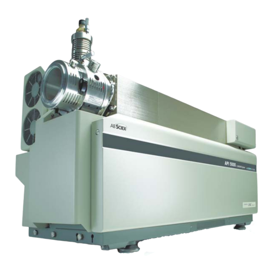
System Overview The API 5000™ LC/MS/MS system includes a triple quadrupole mass spectrometer, a Turbo V™ ion source, a computer, and the Analyst software. ® Mass Spectrometer Bench Line Adjustment Transformers Roughing Pumps Figure 1-1 API 5000™ system and bench WARNING! If you need to move the system, contact an FSE to assist you. -
Page 6: Features Of The Instrument
MRM (Multiple Reaction Monitoring). Features of the Instrument The API 5000 LC/MS/MS system combines all of the features of the API 4000™ LC/MS/MS system with the additional benefits of improved sensitivity and enhanced signal-to-noise ratio. It allows comprehensive analysis of biopharmaceutical compounds and it has the specificity needed for new drug development. -
Page 7: Parts Of The Instrument
Hardware Guide pulses and converts the information into a signal. The signal represents the ion intensity for a particular m/z and the instrument displays this formation as a mass spectrum. For more information, see Figure 1-2 Ion optics path. Interface Region Analyzer Region ®... -
Page 8: I/O Panel
System Overview Control RF FEEDBACK RF FEEDBACK Panel I/O Panel Gas and Vacuum Panel Figure 1-4 Back view I/O Panel The input/output panel on the right-hand side of the chassis has a socket for the external AC power supply, the IEEE-488 (GPIB) connections to the computer, the AUX I/O to the peripherals, and a sources connector for optional sources. -
Page 9: Control Panel
Hardware Guide BACKING PUMP CURTAIN GAS SUPPLY MAX 60 PSIG EXHAUST SUPPLY GAS 1 / GAS 2 EXHAUST WASTE OUT MIN 55 PSIG MAX 105 PSIG MAX 60 PSIG Figure 1-6 Gas and vacuum panel Control Panel The control panel is located on the right side of the instrument. It encloses the power distribution module. -
Page 10: Source Exhaust System
System Overview Spare Output B Heated Nebulizer (APCI) Card Cage Blower Spare Output A WARNING (see Note VACUUM below) POWER STATUS RESET FAULT Figure 1-7 Control panel Source Exhaust System The source exhaust system is a safety feature that isolates the sample vapors and exhaust products from the laboratory environment. -
Page 11: Vacuum Chamber
Hardware Guide Ion Source RF FEEDBACK RF FEEDBACK Front Bulkhead Assembly Pressure Switch Exhaust Supply BACKING PUMP CURTAIN GAS SUPPLY MAX 60 PSIG Venturi Pump EXHAUST SUPPLY GAS 1 / GAS 2 EXHAUST WASTE OUT MIN 55 PSIG MAX105 PSIG MAX 60 PSIG Exhaust Waste Out Gas Panel... - Page 12 System Overview CAUTION! Potential Instrument Damage: Shut off the sample flow before you shut down the instrument. 3. In the Analyst software, deactivate the hardware profile and then close the application software. 4. Stop the Analyst Service. (See the Software Reference Guide for the ®...
-
Page 13: Source/Gas Parameters
Hardware Guide Interlocks (pressure switches) monitored by the firmware detect if the Curtain Gas supply and the roughing pump are switched on. If the interlocks are not satisfied, the turbo pumps are not initiated. CAUTION! If the ion source is removed, the system electronics will be disabled, interrupting any data acquisition tasks. -
Page 14: Turbo V™ Ion Source Settings
The guides and tutorials for the instrument and the Analyst software are installed automatically with the software and are available from the Start menu: All Programs > AB SCIEX. A complete list of the available documentation can be found in the online Help. To view the Analyst software Help, press F1. -
Page 15: Chapter 2 Api 5000 ™ Instrument Parameters
API 5000 Instrument Parameters ™ The following table contains generic parameters for the API 5000™ instrument. The first number under each scan type is the preset value; the range of numbers is the accessible range for each parameter. Table 2-1 API 5000™ Instrument Parameters Positive ion mode Negative ion mode Parameter... - Page 16 API 5000 Instrument Parameters ™ Table 2-1 API 5000™ Instrument Parameters (cont’d) Positive ion mode Negative ion mode Parameter Access MS/MS Q1 MS/MS Q0+ (–20) Q0+ Q0 + 20 Q0 + 20 Q0 + 20 (–20) (–20) (IQ2 = Q0 + offset) –100 to 100 to 8 n/a –8...
Need help?
Do you have a question about the API 5000 LC/MS/MS and is the answer not in the manual?
Questions and answers