
Subscribe to Our Youtube Channel
Related Manuals for Keysight B2980B Series


Summary of Contents for Keysight B2980B Series
- Page 1 Keysight B2980B Series Femto/Picoammeter Electrometer/High Resistance Meter User’s Guide Distributed by: Sie haben Fragen oder wünschen eine Beratung? Angebotsanfrage unter 07121 / 51 50 50 oder über info@datatec.de...
- Page 2 Notices Copyright Notice therein, does not require or permit, among WRITTEN AGREEMENT WITH WARRANTY other things, that Keysight: (1) Furnish techni- TERMS COVERING THE MATERIAL IN THIS © Keysight Technologies 2021 cal information related to commercial com- DOCUMENT THAT CONFLICT WITH THESE...
- Page 3 COMPLIANCE WITH GERMAN NOISE REQUIREMENTS This is to declare that this product is in conformance with the German Regulation on Noise Declaration for Machines (Lärmangabe nach der Maschinenlärminformation-Verordnung -3.GSGV Deutschland). Herstellerbescheinigung • GERÄUSCHEMISSION Lpa < 70 dB am Arbeitsplatz normaler Betrieb nach DIN 45635 T.
- Page 4 Keysight Technologies assumes no liability for customer’s failure to comply with these requirements. For the Lithium-ion battery, also see “Safety Precautions for Lithium-ion Battery (Keysight part number B2980-90100).” Product manuals may also be available on the Web. Go to www.keysight.com...
- Page 5 Instruments that appear damaged or defective should be made inoperative and secured against unintended operation until they can be repaired by qualified service personnel. Return the instrument to a Keysight Technologies sales or service office for services and repair to ensure that safety features are maintained.
- Page 6 Safety Symbols The general definitions of safety symbols used on equipment or in manuals are listed below. Direct current. Alternating current. Earth (ground) terminal. Protective conductor terminal. For protection against electrical shock in case of a fault. Used with field wiring terminals to indicate the terminal which must be connected to ground before operating equipment.
- Page 7 Read operator's manual. To indicate that the operator's manual or card should be read before continuing the operation. Rechargeable battery. CAT I IEC Measurement Category I The CE mark shows that the product complies with all applicable European Directives. UN Transportation Test The CSA mark is a registered trademark of the Canadian Standards Association.
- Page 8 RBRC (Rechargeable Battery Recycling Corporation) Marking. For Canada and USA: Please call 1-800-822-8837 for information on how to recycle this battery. FCC (Federal Communications Commission) Marking, USA Three Arrow Recycling Mark: “mobius” logo and chemical symbols for recycling, Japan PSE (Product Safety Electrical Appliance and Materials) Marking, Japan...
- Page 9 Protection Limits shown on the input terminals. Voltage Source Terminals on Keysight B2985B/B2987B • Keysight B2985B/B2987B can apply DC voltage up to 1050 V between High and Low terminals. Voltage marked between the earth terminal and the Low/Common terminal indicates the floating usage limits.
- Page 10 High Voltage Shock Hazard Keysight B2985B/B2987B can apply dangerous voltages (1050 V) at the High/Low terminal. To prevent electric shock hazard, the following safety precautions must be observed during the use of Keysight B2985B/B2987B. Use a three-conductor AC power cable to appliance coupler (inlet) and the instrument to an •...
- Page 11 Von den Geräten Keysight B2985B/B2987B können Spannungen an des High/Low-Anschlusses von bis zu 1050 V ausgehen. Um elektrischem Schlag vorzubeugen, ist bei der Benützung der Geräte Keysight B2985B/B2987B folgendes zu beachten. Verwenden Sie ein dreiphasiges AC-Stromkabel für die Gerätsteckvorrichtung (Eingang) •...
- Page 12 Danger de choc dû à une haute tension Une tension dangereuse (max. pour; 1050 Vdc) émanant du dispositif Keysight B2985B/B2987B peut être sortie aux la borne High/Low, d'appareil de protection ou de détection. Les précautions suivantes doivent être obserées contre commotion électrique accidentelle.
- Page 13 高電圧感電注意 Keysight B2985B/B2987B High/Low 1050 Vdc • • Interlock • • High/Low • On/Off On/Off • • Interlock • • •...
- Page 14 Product Category: With reference to the equipment types in the WEEE directive Annex 1, this product is classified as a “Monitoring and Control instrumentation” product. Do not dispose in domestic household waste. To return unwanted products, contact your local Keysight office or visit the following website for more information. http://about.keysight.com/en/companyinfo/environment/ Perchlorate Information •...
- Page 15 This chapter explains how to perform measurement by using the Keysight B2980. Chapter 4, “Front Panel Reference” • This chapter provides the reference information of the Keysight B2980 front panel keys and graphical user interface. Chapter 5, “Function Details” •...
-
Page 17: Table Of Contents
Installing Keysight B2980 ........ - Page 18 Maintenance ........... 65 Cleaning .
- Page 19 Setup Parameters ......... . . 122 About Charge Measurement .
- Page 20 Measure Filter Dialog Box........175 Wait Control Dialog Box .
- Page 21 5 Function Details Measurement Range ......... . . 204 Automatic Ranging Speed .
- Page 22 Predefined Math Expressions ........223 Resources Used in the Expressions ......226 Limit Test .
- Page 23 Battery Care ..........269 Supplemental Characteristics .
-
Page 25: Introduction
Keysight B2980B Series User’s Guide Introduction Keysight B2980 Series Front View Rear View Software and Drivers Productivity Tools Accessories Options This chapter describes the basic functions and features of Keysight B2980. -
Page 26: Keysight B2980 Series
Introduction Keysight B2980 Series Keysight B2980 Series Keysight B2980 series provides the products listed below. Differences between models are summarized in Table 1-1. B2981B Femto/Picoammeter • B2983B Femto/Picoammeter with Battery • Ammeter for ultra low DC current measurement in atto ampere resolution B2985B Electrometer/High Resistance Meter •... -
Page 27: Front View
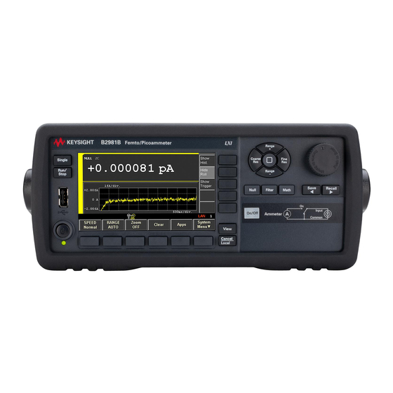
Introduction Front View Front View This section describes the front view of Keysight B2980 series. Standby switch • Turns the instrument on or off. During the power is on, the LED below the switch turns green. After booting up normally, the front panel LCD displays the image as shown below. - Page 28 The following indicators are available. Trigger auto High voltage Voltmeter guard Remote Error LXI LAN status indicator /common Voltage Source floating MOVE View mode Trigger active Local lockout /common Battery operation /EDIT 1/G/H/R Keysight B2980B User’s Guide, Edition 1...
- Page 29 View View Cancel / Local key • Cancels the setup operation if the instrument is in the local state. Returns the instrument to the local state if it is in the remote control state. Keysight B2980B User’s Guide, Edition 1...
- Page 30 Expression dialog box. Pressing OK after setting up the dialog box enables the math function and turns the MATH indicator on. If the MATH indicator has turned on, pressing the Math key disables the function and turns the MATH indicator off. Keysight B2980B User’s Guide, Edition 1...
- Page 31 On (green) switch turns it to the Off status even if the instrument is in the remote control state. Voltmeter, • for B2985B and B2987B No switch for Voltmeter. The voltmeter is always effective. Voltage Source On/Off switch, • for B2985B and B2987B Keysight B2980B User’s Guide, Edition 1...
- Page 32 Lithium-ion rechargeable battery. 80 % 60 % 40 % 20 % 20 % When the instrument power is off and the battery charging is in progress, the LED below the standby switch turns orange. Keysight B2980B User’s Guide, Edition 1...
-
Page 33: To Use The Field Pointer
Turning the rotary knob or pressing the Range /Range key on the decimal • point moves the decimal point if real time update is OFF. For the real time update, see “Voltage Source Output (B2985B/ B2987B)” on page Keysight B2980B User’s Guide, Edition 1... -
Page 34: To Change The Settings On A Dialog Box
To cancel the setting change, press the Cancel/Local key instead of Apply. Summary of Front Panel Operation Front panel operations are summarized in Tables 1-2 to 1-9. For details, see Chapter 4, “Front Panel Reference.” Keysight B2980B User’s Guide, Edition 1... - Page 35 Cancel/Local key To clear measurement buffer Clear function key To launch the setup integrity checker Apps function key > #1 assist key To launch the data logger Apps function key > #2 assist key Keysight B2980B User’s Guide, Edition 1...
- Page 36 Voltmeter input terminal for B2985B/B2987B To enable or disable the automatic System Menu > Config > Measure > Coulomb > Auto Dis. function discharge function for the charge keys measurement for B2985B/B2987B Keysight B2980B User’s Guide, Edition 1...
- Page 37 System Menu > Config > Measure > Volts > Attn. function keys measurement with the Keysight N1413A/N1414A adapter for B2985B/B2987B To set up the source and measurement wait System Menu > Config > Common > Wait function keys time for B2985B/B2987B Keysight B2980B User’s Guide, Edition 1...
- Page 38 To show or hide source output preview Show Preview or Hide Preview assist key To set the level of the source output applied Range setup sub-panel on the Meter view by receiving a trigger Keysight B2980B User’s Guide, Edition 1...
- Page 39 System Menu > File > Load > License function keys To load a list sweep data from a USB flash drive Load assist key for the list sweep Start/Stop/Points field in the EDIT status Keysight B2980B User’s Guide, Edition 1...
- Page 40 To set trigger parameters on sub-panel Show Trigger assist key To set trigger parameters in detail System Menu > Trigger > Config function keys To control trigger system System Menu > Trigger > Initiate/Abort/Immediate function keys Keysight B2980B User’s Guide, Edition 1...
- Page 41 System Menu > I/O > DIO > Config function keys To read or write a value set to Digital I/O System Menu > I/O > DIO > R/W function keys To set BNC Trigger In/Out System Menu > I/O > BNC function keys Keysight B2980B User’s Guide, Edition 1...
- Page 42 System Menu > System > Info. > Demo. function keys To load a system setting data System Menu > File > Load > Config function keys To install license file System Menu > File > Load > License function keys Keysight B2980B User’s Guide, Edition 1...
-
Page 43: Rear View
Introduction Rear View Rear View This section describes the rear view of Keysight B2980 series. B2981B/B2983B B2985B/B2987B Ammeter input connector • Triaxial connector for current measurement. Input Common Ammeter ON or OFF can be controlled by the On/Off switch. Keysight B2980B User’s Guide, Edition 1... - Page 44 Utiliser également des accessoires qui sont conformes à la norme IEC 61010-031. Toutes les bornes et les conducteurs prolongés doivent être isolés en utilisant des bouchons d'isolation, des manchons, etc. Keysight B2980B User’s Guide, Edition 1...
- Page 45 AC power cord is connected to this receptacle. Serial Number • You will need the instrument’s serial number when using Keysight Technologies telephone assistance program. The serial number label is attached to the bottom of the instrument. Keysight B2980B User’s Guide, Edition 1...
- Page 46 Dangerous voltage of up to the maximum voltage of 1050 V may be present between the High and Low terminals of the Voltage Source if the Interlock terminal is closed. Keysight B2980B User’s Guide, Edition 1...
- Page 47 EE07 or equivalent. The humidity sensor and the connection cable are not furnished with the instrument. Thermocouple connector, for B2985B and B2987B • Connector for Type K thermocouple used for temperature measurements. One thermocouple, Keysight N1423A is furnished with the instrument. Keysight B2980B User’s Guide, Edition 1...
-
Page 48: Software And Drivers
This allows you to control one B2980 over a LAN connection. IVI-C or IVI-COM drivers • Compatible with Keysight IO Libraries Suite 17.0 or later. Supports Keysight VEE, Microsoft Visual Studio (Visual Basic, Visual C, Visual C#), National Instruments LabWindows and LabVIEW. LabVIEW driver (VI) •... -
Page 49: Productivity Tools
Introduction Productivity Tools Productivity Tools Table 1-10 lists the productivity tools for Keysight B2980. Table 1-10 Productivity Tools Model Number Option Item Description N1410A Starter kit for B2985B/B2987B Triaxial to alligator clip cable, 200 V, 1.5 m, 1 ea. •... -
Page 50: Accessories
Interlock connector head, 1 ea. for B2985B/B2987B • Humidity probe connector head, 1 ea. for B2985B/B2987B • Available Accessories For the available accessories for the Keysight B2980B series, see the catalog. To get the latest information, go to www.keysight.com/find/b2980 and click “Technical Support.”... -
Page 51: Options
Introduction Options Options Table 1-11 lists the options for Keysight B2980. Table 1-11 Options Option Description Calibration, uncertainties, and guardbanding (not accredited) ANSI Z540 compliant calibration Commercial calibration certificate with test data Keysight B2980B User’s Guide, Edition 1... - Page 52 Introduction Options Keysight B2980B User’s Guide, Edition 1...
-
Page 53: Installation
Keysight B2980B Series User’s Guide Installation Inspecting the Shipment Installing Keysight B2980 Maintenance Installing the Interlock Circuit Connecting to the Interfaces Communicating Over the LAN Using Digital I/O and Trigger In/Out This chapter describes how to install Keysight B2980. - Page 54 Confirm that the On/Off switch does not turn red. • Open the fixture cover or the shielding box access door (open interlock). • Discharge any capacitors connected to the terminal. • Warn persons working around the instrument about dangerous conditions. • Keysight B2980B User’s Guide, Edition 1...
- Page 55 Ouvrez le couvercle d'appareil ou la protection du boîtier de la porte • d'accès (verrouillage ouvert). Déchargez tous les condensateurs connectés au réseau. • Informez les personnes se trouvant à proximité de l'appareil à propos des • conditions dangereuses. Keysight B2980B User’s Guide, Edition 1...
-
Page 56: Inspecting The Shipment
Installation Inspecting the Shipment Inspecting the Shipment Perform the following inspections when Keysight B2980 and accessories arrive at your site. 1. Before unpacking any component, inspect all boxes for any signs of damage that might have occurred during shipment, such as: dents •... -
Page 57: Checking For Errors
1. Press the System Menu > System > Error > Log function keys. This opens the Error Log dialog box. 2. Check the errors displayed on the dialog box. If no error is detected, “0, No Error” is displayed. 3. Press OK to close the dialog box. Keysight B2980B User’s Guide, Edition 1... -
Page 58: Installing Keysight B2980
Ne pas utiliser l’appareil en présence de gaz inflammables ou de fumée. Environmental conditions for the B2980 are described below. The B2980 is designed for use in indoor facilities. Temperature range • Operating 0 C to 45 C Keysight B2980B User’s Guide, Edition 1... -
Page 59: Connecting The Power Cord
Risques de choc électrique : le cordon d’alimentation fournit la masse par le biais d’un troisième conducteur. Assurez-vous de connectez la prise d'alimentation de type trois conducteurs au boîtier exact mis à terre. Keysight B2980B User’s Guide, Edition 1... - Page 60 Connect the power cord to the IEC 320 connector on the rear of the instrument. If the wrong power cord was shipped with your instrument, contact Keysight Technologies. The AC input on the back of your instrument is a universal AC input.
- Page 61 • PN: 8120-8376 PN: 8121-0564 • • • Option 931 Option 932 Plug: CNS 10917-2, Plug: CS 0017, • • 125 V, 10 A 250 V, 10 A PN: 8121-1635 PN: 8121-1638 • • Keysight B2980B User’s Guide, Edition 1...
-
Page 62: Setting The Power Line Frequency
For easier display viewing and front panel access, you can tilt up the front of the instrument by turning the handle. To adjust the handle, grab the handle by the sides and pull outward. Then, rotate the handle to the desired position. Keysight B2980B User’s Guide, Edition 1... -
Page 63: Rack Installation
To avoid this, make a space about 2U (approx. 10 cm) above the instrument. Keysight B2980 can be mounted in a 19-inch EIA rack cabinet. It is designed to fit in two rack-units (2U) of space. - Page 64 Installation Installing Keysight B2980 3. Pull outward and then lift the handle upward. When reattaching the handle, pay attention to its direction. Incorrect attachment may damage the hard ware. Keysight B2980B User’s Guide, Edition 1...
-
Page 65: Maintenance
Installation Maintenance Maintenance Maintenance should be performed periodically to keep Keysight B2980 in good condition. If problems arise, contact Keysight Technologies. “Cleaning” • “Self-test” • “Self-calibration” • “Calibration” • Cleaning SHOCK HAZARD: To prevent electric shock, unplug the B2980 before cleaning. -
Page 66: Self-Calibration
Confirmation dialog box is opened. 5. Press OK. This starts the self-test. Self-calibration Keysight B2980 provides the self-calibration function to maintain the measurement performance. If the environmental temperature changes 3 C or more, perform the self-calibration. This is effective for the accurate measurements by minimizing the effect of thermal drift. -
Page 67: Calibration
It is recommended to perform the calibration once a year at least. For the calibration and adjustments, contact Keysight Technologies. Trained service personnel will perform the calibration and adjustments. Keysight B2980B User’s Guide, Edition 1... -
Page 68: Installing The Interlock Circuit
Installation Installing the Interlock Circuit Installing the Interlock Circuit This section is applied to Keysight B2985B/B2987B which supports the interlock function. The interlock circuit is a simple electric circuit, as shown in Figure 2-2. The circuit electrically opens when an access door is opened, and closes when the door is closed. - Page 69 10 mA at 2 V in High voltage status Ground Interlock connector head, 4-pin plug Access door Mechanical switches connected to B2985B/B2987B Interlock connector Interlock circuit Figure 2-3 Dimensions of the LED (Keysight part number 1990-0486) Cathode (-) Anode (+) Units: mm Keysight B2980B User’s Guide, Edition 1...
- Page 70 Installation Installing the Interlock Circuit Figure 2-4 Dimensions of the Interlock Switch (Keysight N1254A-402) 10.3 4.75 35.6 Switch off 15.3 10.3 15.9 18.8 C OM 22.2 27.8 Units: mm Keysight B2980B User’s Guide, Edition 1...
-
Page 71: Connecting To The Interfaces
GPIB/USB Interfaces For detailed information about GPIB and USB interface connections, refer to Connectivity Guide installed with Keysight IO Libraries. The following steps will help you quickly get started connecting your instrument to the GPIB (General Purpose Interface Bus). The following figure illustrates a typical GPIB interface system. - Page 72 Installation Connecting to the Interfaces 1. If you have not already done so, install Keysight IO Libraries Suite from the CD shipped with your product. 2. If you do not have a GPIB interface card installed on your computer, turn off your computer and install the GPIB card.
-
Page 73: Lan Interface
To network interface card (NIC). Instrument 1. If you have not already done so, install Keysight IO Libraries Suite from the CD shipped with your product. 2. Connect the instrument to the site LAN. The factory-shipped instrument LAN settings are configured to automatically obtain an IP address from the network using DHCP (DHCP: Enabled). - Page 74 LAN settings from the front panel of the instrument. 3. Use the Connection Expert utility from Keysight IO Libraries Suite to add the B2980 and verify the connection. To add the instrument, you can request Connection Expert to discover the instrument.
-
Page 75: Communicating Over The Lan
Internet Explorer 6 or Firefox 2. You will also need the Java Plug-in. This is included in the Java Runtime Environment. Refer to Java’s website. The graphical web interface is enabled when shipped. Keysight B2980B User’s Guide, Edition 1... -
Page 76: Using Telnet
4. For additional help about any page, click “Help with this Page.” If desired, you can control the access to the graphical web interface using password protection. As shipped from the factory, the password is set to Keysight or keysight. To change the password, click on the View & Modify Configuration button. - Page 77 When SRQ becomes true, the instrument will send the string “SRQ nn” to the client. The “nn” is the status byte value, which the client can use to determine the source of the service request. Keysight B2980B User’s Guide, Edition 1...
-
Page 78: Using Digital I/O And Trigger In/Out
BNC connector on the external equipment to send a trigger signal to it. Figure 2-5 shows the input/output circuits internally connected to each pin of the Digital I/O connector and the Trigger In/Out connector. Keysight B2980B User’s Guide, Edition 1... - Page 79 Vcc: +5 V R1: 5 kohm R2: 100 ohm Table 2-1 Digital I/O Pin Assignment Pin Number Description DIO 1 DIO 2 DIO 3 DIO 4 DIO 5 DIO 6 DIO 7 5 V Keysight B2980B User’s Guide, Edition 1...
- Page 80 Installation Using Digital I/O and Trigger In/Out Keysight B2980B User’s Guide, Edition 1...
-
Page 81: How To Perform Measurement
Keysight B2980B Series User’s Guide How to Perform Measurement Current Measurement Voltage Measurement Resistance Measurement Charge Measurement Temperature and Humidity Measurement Measurement Considerations This chapter explains how to perform measurement by using Keysight B2980. - Page 82 (ground) terminal on the rear panel, for safety. Use the earthing wire furnished with the B2983B/B2987B. Keysight B2980B User’s Guide, Edition 1...
- Page 83 Press the Single key to start a single (one shot) measurement. Press the Run/Stop key to start a repeat (continuous) measurement. If a repeat measurement is in progress, pressing the Single or Run/Stop key stops Keysight B2980B User’s Guide, Edition 1...
- Page 84 Generally, environmental conditions, such as electromagnetic environment, have a negative impact on the performance of the instrument. Use coaxial cables and shielding technique to minimize the impact. Keysight B2980B User’s Guide, Edition 1...
-
Page 85: Current Measurement
Banana to lug cable, for connecting Common to chassis ground • Instead of the triaxial cable and the triaxial bulkhead connector, Keysight N1415A Triaxial to alligator clip cable, 200 V, 1.5 m can be used. Keysight B2980B User’s Guide, Edition 1... - Page 86 Common is connected to chassis ground by using Banana-to-lug cable. Chassis Ground Common Figure 3-3 Current Measurement Connection (if DUT has a non-ground potential) Safety Shield Guard shield Triaxial bulkhead connector Triaxial cable Chassis ground Safety Earth ground Chassis Common ground Keysight B2980B User’s Guide, Edition 1...
- Page 87 Press the Run/Stop key to start a repeat (continuous) measurement. Current • measurement is performed repeatedly. Minimum measurement interval is 10 Step 8. Press the Ammeter On/Off switch to disable Ammeter. This turns off the switch light. Keysight B2980B User’s Guide, Edition 1...
-
Page 88: Setup Parameters
Press the SPEED function key to change the aperture mode, auto or manual. Where, the softkey label shows the present aperture time setting. Aperture time can be set by using the following navigation keys. Coarse Res Increases measurement speed (decreases aperture time). Keysight B2980B User’s Guide, Edition 1... -
Page 89: Measurement Range
The measurement range can be set by using the following navigation keys. Range + Sets the fixed range and changes the range up. [home] Sets the AUTO range and the Normal auto aperture. Range Sets the fixed range and changes the range down. Keysight B2980B User’s Guide, Edition 1... -
Page 90: Aperture Time
For accurate and reliable measurements, the aperture time should be increased. The following aperture modes are available. The mode can be selected by pressing the SPEED function key. Where, the softkey label shows the present aperture time setting. Keysight B2980B User’s Guide, Edition 1... - Page 91 The aperture time can be set by using the following navigation keys. Coarse Res Coarse resolution. Increases measurement speed (decreases aperture time). [home] Sets the Normal auto aperture and the AUTO range. Fine Res Fine resolution. Decreases measurement speed (increases aperture time). Keysight B2980B User’s Guide, Edition 1...
-
Page 92: Common Terminal Connection
Guarding technique covers the wire connecting from the Input of Ammeter with a conductor (Guard) that has same potential as Input to cancel the potential difference from the surrounding dielectric so that the leakage current can be Keysight B2980B User’s Guide, Edition 1... - Page 93 à la norme IEC 61010-031. Toutes les bornes et les conducteurs prolongés doivent être isolés en utilisant des bouchons d'isolation, des manchons, etc. Do not apply current to the chassis ground. Doing so will damage the instrument. Keysight B2980B User’s Guide, Edition 1...
-
Page 94: Voltage Measurement
Banana to lug cable, for connecting Common to chassis ground • Instead of the triaxial cable and the triaxial bulkhead connector, Keysight N1415A Triaxial to alligator clip cable, 200 V, 1.5 m can be used. When turning the instrument on, leave the end of the measurement path open. - Page 95 Figure 3-7 Guarded Voltage Measurement Connection Shield Chassis ground Triaxial cable Triaxial bulkhead connector Banana-to-alligator clip cable Guard shield Common is connected to chassis ground by using Banana-to-lug cable. Safety Earth Ground Common Chassis Ground Keysight B2980B User’s Guide, Edition 1...
- Page 96 “Measure Volts” on page 99 for more information. Step 4. Use the navigation keys or the SPEED function key to set the measurement speed (aperture time) you desire. See “Aperture Time” on page 99 for more information. Keysight B2980B User’s Guide, Edition 1...
- Page 97 The B2985B/B2987B may show the voltage around 20 V or OVERFLOW just after turning on or during the voltage measurement. This is caused by the internal circuit when the voltmeter input is open. This operation is normal, not failure. Keysight B2980B User’s Guide, Edition 1...
-
Page 98: Setup Parameters
To set the value, use the assist key and/or the rotary knob, and press OK to apply the setting and close the dialog box. Figure 3-9 Differences between GUARD and CCOM Input Buffer amplifier Guard Guard Voltage under test Common Input Common CCOM Voltage under test Keysight B2980B User’s Guide, Edition 1... - Page 99 Pressing OK after setting up the dialog box enables the filter function and turns the FILT indicator on. If the FILT indicator is turned on, pressing the Filter key disables the function and turns the FILT indicator off. Keysight B2980B User’s Guide, Edition 1...
-
Page 100: Guarding
Therefore, you can make the precise and fast measurement even for the voltage source under test that has the large output resistance. Keysight B2980B User’s Guide, Edition 1... - Page 101 Common Output Buffer amplifier resistance Voltage Guard under test Common Never connect the Guard terminal to any output, including circuit common, chassis ground, or any other guard terminal. Doing so will damage the instrument. Keysight B2980B User’s Guide, Edition 1...
-
Page 102: Resistance Measurement
Keysight N1414A High resistance measurement universal adapter • Instead of the triaxial cable and the triaxial bulkhead connector, Keysight N1415A Triaxial to alligator clip cable, 200 V, 1.5 m can be used. When turning the instrument on, leave the end of the measurement path open. - Page 103 To apply a voltage over 21V, the Interlock terminal must be connected to an interlock circuit. See “Interlock” on page 112. To attach the N1413A/N1414A adapter, push it to the B2985B/B2987B connectors. Push the adapter in firmly until it locks in-place (< 1 mm spacing) Keysight B2980B User’s Guide, Edition 1...
- Page 104 Input Banana-to-lug cable Common Shield Voltage Source Low terminal is internally connected to or disconnected from the circuit common as shown in Figure 3-12. See “Low Terminal State” on page 110 for more information. Keysight B2980B User’s Guide, Edition 1...
- Page 105 Common FLOATING Shield (but connected to chassis by N1414A adapter) For the floating device measurement, set the N1414A control switch to the PULL position. Also set the voltage source Low terminal state to FLOATING. Keysight B2980B User’s Guide, Edition 1...
- Page 106 Voltage Source. The voltage up to 500 V can be applied to the Common terminal. Voltage Source Low terminal is internally connected to or disconnected from the circuit common as shown in Figure 3-14. See “Low Terminal State” on page 110 for more information. Keysight B2980B User’s Guide, Edition 1...
- Page 107 Step 2. Press the View key and select the Meter View function key to display the Meter view. Step 3. Press the OHMS (R) assist key to set the resistance measurement mode. Step 4. Set the current measurement range and the output voltage. See “V Control Mode” on page 109. Keysight B2980B User’s Guide, Edition 1...
- Page 108 Setup” on page 115. To perform the list sweep measurement, see “List Sweep Output Setup” on page 116. To perform the measurement with the square wave voltage output, see “Square Wave Output Setup” on page 118. Keysight B2980B User’s Guide, Edition 1...
-
Page 109: Setup Parameters
Source assist key and set the value into the Voltage Source field by using the rotary knob and/or the assist key. To see these assist keys, you may need to press the More... 1 of 3 assist key and/or the More... 2 of 3 assist key. Keysight B2980B User’s Guide, Edition 1... - Page 110 High potential. And it must be less than or equal to 500 V for chassis ground. When Keysight N1413A or N1414A adapter is used, Voltage Source Low is connected to chassis ground through the adapter. So, set the Low terminal state to FLOATING when using the adapter.
- Page 111 Coarse Res Increases measurement speed (decreases aperture time). [home] Sets the Normal auto aperture and the AUTO range. Fine Res Decreases measurement speed (increases aperture time). “Aperture Time” on page 90 for more information. Keysight B2980B User’s Guide, Edition 1...
-
Page 112: Interlock
Interlock Circuit” on page If the interlock circuit is opened during Voltage Source applies a voltage over 21 V, the output voltage is set to 0 V immediately and the output relay is opened. Keysight B2980B User’s Guide, Edition 1... -
Page 113: Voltage Source
And the voltage source starts output. Step 6. Press the Voltage Source On/Off switch to disable the output. This turns off the switch light. Procedure 2 You can apply sweep voltage as follows. Keysight B2980B User’s Guide, Edition 1... - Page 114 Step 6. Press the Voltage Source On/Off switch to disable the output. This turns off the switch light. Floating Low With the default setting, Voltage Source Low terminal is connected to the circuit common. However, it can be internally disconnected from the common for making the floating condition. Keysight B2980B User’s Guide, Edition 1...
- Page 115 Voltage Source supports the following staircase sweep output. Linear single sweep • Voltage Source applies staircase sweep voltage from start to stop in a step. This sweep is available when VS Function is set to LINEAR SINGLE. Linear double sweep • Keysight B2980B User’s Guide, Edition 1...
- Page 116 Show VS Func. assist key. To see the assist key, you may need to press the More... 1 of 3 assist key and/or the More... 2 of 3 assist key. And set LIST to the VS Function field. The sub-panel shows the following information. Keysight B2980B User’s Guide, Edition 1...
- Page 117 Insert Adds a line above. The same output value is entered into the right cell. Delete Deletes the line. Scroll 100 Moves the pointer to the maximum 100 points above. Keysight B2980B User’s Guide, Edition 1...
- Page 118 Show VS Func. assist key. To see the assist key, you may need to press the More... 1 of 3 assist key and/or the More... 2 of 3 assist key. VS Function ARB SQUARE Start Square wave base voltage, in V Peak Square wave peak voltage, in V Keysight B2980B User’s Guide, Edition 1...
- Page 119 Period of base output after peak, in s Count Number of square wave outputs To set the parameter value, use the assist key and/or the rotary knob. To confirm the waveform, press the Show Preview assist key. Keysight B2980B User’s Guide, Edition 1...
-
Page 120: Charge Measurement
Banana to lug cable, for connecting Common to chassis ground • Instead of the triaxial cable and the triaxial bulkhead connector, Keysight N1415A Triaxial to alligator clip cable, 200 V, 1.5 m can be used. When turning the instrument on, leave the end of the measurement path open. - Page 121 Step 7. Connect measurement charge (DUT) to the Ammeter input connector. See Figure 3-17 for the connection. Step 8. Press the Ammeter On/Off switch to enable the coulomb meter. This turns the switch green. Step 9. Start measurement as follows. Keysight B2980B User’s Guide, Edition 1...
-
Page 122: Setup Parameters
Sets the fixed range mode and changes the range up. [home] Sets the AUTO range and the Normal auto aperture. Range Sets the fixed range mode and changes the range down. “Measurement Range” on page 89 for more information. Keysight B2980B User’s Guide, Edition 1... -
Page 123: About Charge Measurement
The capacitance value is known and accurate. And the capacitance C, charge Qs, and voltage V are expressed by the following formula. --- - i t d ------ - Keysight B2980B User’s Guide, Edition 1... -
Page 124: Temperature And Humidity Measurement
Before turning the instrument on, connect accessory used for the measurement. Figure 3-18 for connection. The following accessories can be used. Thermocouple, type K, 3.5 m, Keysight N1423A • Humidity sensor, EE Elektronik EE07 or equivalent, and connection cable •... - Page 125 THERMOCOUPLE: Uses thermocouple for temperature measurement (factory default setting) HUMIDITY SENSOR: Uses humidity sensor for temperature measurement 4. Set the Humidity field as follows. ON: Enables humidity measurement (factory default setting) OFF: Disables humidity measurement Keysight B2980B User’s Guide, Edition 1...
-
Page 126: Measurement Considerations
Water and water vapor can easily cause electrochemical effects. It is effective to maintain constant low humidity in the measurement environment in order to prevent the occurrence of an electrochemical effect. Temperature changes can Keysight B2980B User’s Guide, Edition 1... -
Page 127: Offset
Generally, using the low noise coaxial cable can reduce the noise caused by vibration. Also fixing the cable is effective for preventing it from vibration. Note that applying too much stress to the cable or bending it tightly will have a detrimental effect on the measurements. Keysight B2980B User’s Guide, Edition 1... -
Page 128: External Noise
So it is important to wait enough time until the current converges. Noise current caused by dielectric absorption Ammeter Time Voltage source Insulation material Time Keysight B2980B User’s Guide, Edition 1... -
Page 129: Capacitive Coupling
Current caused by light is unstable and slow to change. It is important to apply shielding for cutting off the light and to prevent reflection inside the shielding. Keysight B2980B User’s Guide, Edition 1... - Page 130 How to Perform Measurement Measurement Considerations Keysight B2980B User’s Guide, Edition 1...
-
Page 131: Front Panel Reference
Config Key Group Function Key Group Trigger Key Group Result Key Group File Key Group Program Key Group I/O Key Group Display Key Group System Key Group This chapter provides reference information of Keysight B2980 front panel keys and display. -
Page 132: Hard Keys And Rotary Knob
Acquire trigger (measurement trigger): Initiate • ARM acquire count: Infinite • ARM acquire source: AUTO (automatic internal) • TRIGger acquire count (Measure Count): 100 • TRIGger acquire source (Measure Trigger): AUTO (automatic internal) • Keysight B2980B User’s Guide, Edition 1... - Page 133 “Stable Normal Quick” order. In the manual aperture mode, changes the aperture time in “100.0 PLC 10.0 PLC 1.0 PLC 0.1 PLC 0.01 PLC 0.001 PLC” order. Keysight B2980B User’s Guide, Edition 1...
- Page 134 140. The Coarse Res, Fine Res, Range , and Range keys can be also used for editing the parameter values in the fields. See “Key Functions for Changing the Settings” on page 137. Keysight B2980B User’s Guide, Edition 1...
- Page 135 If the MATH indicator is turned off, pressing the Math key opens the Math Expression dialog box. Pressing OK after setting up the dialog box enables the math function and turns the MATH indicator on. Keysight B2980B User’s Guide, Edition 1...
- Page 136 The Save key is also assigned to the left arrow key. The Recall key is also assigned to the right arrow key. For the details, see “Key Functions for Changing the Settings” on page 137. Keysight B2980B User’s Guide, Edition 1...
-
Page 137: Key Functions For Changing The Settings
2. Press the rotary knob to fix the field to be edited. The field pointer goes in the EDIT status. 3. Turn the rotary knob, or press the Range or Range key to change the setting value. Keysight B2980B User’s Guide, Edition 1... - Page 138 OFF. For the real time update, see Immediate Voltage Update by Knob in“Display Preference Dialog Box” on page 197. For the editing operation of the alphanumeric characters using the helper panel, “Helper Panel” on page 169. Keysight B2980B User’s Guide, Edition 1...
-
Page 139: Display And Assist/Function Keys
Front Panel Reference Display and Assist/Function Keys Display and Assist/Function Keys Keysight B2980 provides several display modes. The display mode is changed by pressing the View key. For each display mode, six function keys are available below the display, and five assist keys are available on the right side of the display. -
Page 140: Meter View
MATH: If the math function is effective. 3. The following sub-panel or condensed graph can be displayed. You can switch them using Show/Hide XXXX assist keys. Range setup sub-panel • Trigger setup sub-panel • Keysight B2980B User’s Guide, Edition 1... - Page 141 Real-time noise monitor • 4. Function keys “Function Keys” on page 144. 5. Assist keys “Assist Keys” on page 149. On the B2981B/B2983B, Assist keys 1 and 3 described in “Assist Keys” are not displayed. Keysight B2980B User’s Guide, Edition 1...
- Page 142 NULL: If the null (offset cancel) function is effective. ZC: If the zero correction function is effective. FILT: If the measurement filter is set. MATH: If the math function is effective. OC: If over current is detected in the voltage source. Keysight B2980B User’s Guide, Edition 1...
- Page 143 5. Assist keys “Assist Keys” on page 149. 6. Voltage Source: Output voltage of the voltage source 7. Source shape indicator. DC, staircase sweep, list sweep, or square wave. DC does not show the indicator. Keysight B2980B User’s Guide, Edition 1...
- Page 144 Clears the data buffer. The graph display is also cleared. Apps Launches the following applications. Use the assist keys to select an application. Setup integrity checker. See “Setup integrity checker” on page 145. Data logger. See “Data logger” on page 146. Keysight B2980B User’s Guide, Edition 1...
- Page 145 MECMMDDhhmmss.csv Where, MM means a month, DD means a day, hh means a hour, mm means a minute, and ss means a second. Function Key Close Closes the Setup Integrity Checker panel. Keysight B2980B User’s Guide, Edition 1...
- Page 146 Settings in the Trace Buffer Setup dialog box and Trigger Setup sub-panel are ignored. Trace Buffer Setup Feed Data: SENSE • Buffer Control: NEXT • Buffer Size: A value specified in the Samples field • Keysight B2980B User’s Guide, Edition 1...
- Page 147 1. Clears the trace buffer. 2. Turns the input/output switches on and then applies the defined Source Value voltage. 3. Waits for the defined Charge Time while the applied voltage is charging the DUT. Keysight B2980B User’s Guide, Edition 1...
- Page 148 Charge Time Wait time after starting the voltage forcing until performing the 1st measurement. Interval Interval between measurements. Repeat Count Repeat count of measurements. 4. Press OK (function key) to start the sequential measurement. Keysight B2980B User’s Guide, Edition 1...
- Page 149 151, and changes the softkey label to Show Hist.. Show Roll Displays the condensed roll graph and changes the softkey label to Hide Roll. Hide Roll Displays the range setup sub-panel and changes the softkey label to Show Roll. Keysight B2980B User’s Guide, Edition 1...
- Page 150 (B2985B/B2987B) Displays the range setup sub-panel and changes the softkey label to Show VS Func.. More... (B2985B/B2987B) Changes the assist keys to Assist keys 1. Softkey labels Show XXXX and Hide XXXX are switched by pressing the key. Keysight B2980B User’s Guide, Edition 1...
- Page 151 Uses the proper range from 200 nC range to 2 C range automatically. LOW (2nC-20nC) Uses the proper range from 2 nC range to 20 nC range automatically. For the FIXED mode, set the range value in the right field. Keysight B2980B User’s Guide, Edition 1...
- Page 152 (B2985B/B2987B) Specifies a constant voltage output value by a trigger input. The voltage source changes the output to the specified value by receiving a trigger signal. This is available in the status VS Function OFF and Voltage Source On. Keysight B2980B User’s Guide, Edition 1...
- Page 153 Sets the peak voltage of square waveform. Delay Sets a period of base output before peak. Peak Time Sets a period of peak output. End Time Sets a period of base output after peak. Keysight B2980B User’s Guide, Edition 1...
- Page 154 When the left cell is in the EDIT status, the following assist keys are available for creating and scrolling the list. Then turning the rotary knob scrolls the list and pressing the knob changes the status to MOVE. Keysight B2980B User’s Guide, Edition 1...
- Page 155 The following data can be loaded as the list sweep data. Comma separated value format, file extension csv • For example, 1.0,1.1,1.2,1.3 Carriage return or line feed separated value format, file extension txt • For example, Keysight B2980B User’s Guide, Edition 1...
- Page 156 Front Panel Reference Display and Assist/Function Keys Space separated value format in a line, file extension prn • For example, 1.0 1.1 1.2 1.3 Keysight B2980B User’s Guide, Edition 1...
- Page 157 For the other trigger type, set the number of triggers required for each source output and measurement properly. For example, set Source Count = Measure Count = 10 for the sweep measurement with 10 steps. Keysight B2980B User’s Guide, Edition 1...
- Page 158 Trigger = EXTn uses a signal from the DIO pin n which is an output port of the Digital I/O D-sub connector on the rear panel. n=1 to 7. Trigger = TIN uses a signal from the Trigger In connector on the rear panel. Keysight B2980B User’s Guide, Edition 1...
- Page 159 The Meter view setup is given priority over the trigger layer setup on the Trigger Configuration dialog box. Hence, the overlapped parameter values on the dialog box are ignored. Keysight B2980B User’s Guide, Edition 1...
-
Page 160: Graph View
B2985B/B2987B: I (A), Q (C), V (V), R (), MATH, SRC, or t (s) 4. X-axis scale: LINEAR or LOG. Select one using the assist keys. 5. Graph maximum value 6. Graph minimum value Keysight B2980B User’s Guide, Edition 1... - Page 161 For the system menu, see “System Menu” on page 170. Assist keys Dump Screen Opens the File Selection (Dump Screen) dialog box which is used to save the screen dump as a JPEG file. Keysight B2980B User’s Guide, Edition 1...
- Page 162 Number of data is 5001 to 10000: [2*(n1)1]th data Number of data is 10001 to 25000: [5*(n1)1]th data Number of data is 25001 to 50000: [10*(n1)1]th data Number of data is 50001 to 100000: [20*(n1)1]th data Keysight B2980B User’s Guide, Edition 1...
-
Page 163: Histogram View
Show Source or Hide Source assist key). If the Voltage Source On/Off switch is turned on, the output value is displayed in yellow. You can change the output voltage using this field. 9. Function keys 10. Assist keys Keysight B2980B User’s Guide, Edition 1... - Page 164 Displays the output voltage value of the voltage source and changes the softkey label to Hide Source. Hide Source Hides the output voltage value of the voltage source and changes the softkey label to Show Source. Keysight B2980B User’s Guide, Edition 1...
-
Page 165: Roll View
9. Y-axis data at the active X-cursor position. ----.---- is displayed for the no-data position. 10. Cursor data (controlled by the Line 1 Cursors or Hide Cursors assist key) Keysight B2980B User’s Guide, Edition 1... - Page 166 Displays the reference line using the saved measurement data as the reference line data, and changes the softkey label to Hide Ref. Hide Ref. Hides the reference line, changes the softkey label to Show Ref. Keysight B2980B User’s Guide, Edition 1...
- Page 167 Number of data is 5001 to 10000: [2*(n1)1]th data Number of data is 10001 to 25000: [5*(n1)1]th data Number of data is 25001 to 50000: [10*(n1)1]th data Number of data is 50001 to 100000: [20*(n1)1]th data Keysight B2980B User’s Guide, Edition 1...
-
Page 168: Status Information
LXI LAN status indicator. Green indicates normal LAN status. Red indicates abnormal condition. Blinking indicates the LAN identification status. white Display mode: Meter view white Display mode: Graph view white Display mode: Roll view white Display mode: Histogram view Keysight B2980B User’s Guide, Edition 1... -
Page 169: Helper Panel
Enters a new entry into the field in the predetermined form such as MEASUREMMDDhhmmss for the file name of the measurement data. Where, MM means a month, DD means a day, hh means an hour, mm means a minute, and ss means a second. Keysight B2980B User’s Guide, Edition 1... -
Page 170: System Menu
Front Panel Reference System Menu System Menu Keysight B2980 has the function keys, including the System Menu key, below the front panel display. Press the System Menu key to display the following softkey menu items. Softkey menu 1 Config Measurement and voltage source configuration setup. Displays the softkeys for setting several functions of the meter and the voltage source. -
Page 171: Config Key Group
(superposed from AC power, etc.) is low. The softkey displays the present Normal/Fast status of this function. Pressing this key switches the status. Coulomb (B2985B/B2987B) Displays the following softkeys for setting the automatic discharge function of the charge measurement. Keysight B2980B User’s Guide, Edition 1... - Page 172 Measure Amps, Spot Source Range, and Voltage Source field settings. If Auto is set, the resistance measurement is performed with the condition automatically derived from the Measure Ohms field setting. Keysight B2980B User’s Guide, Edition 1...
-
Page 173: Output Connection Dialog Box
(B2985B/B2987B) This dialog box provides the following parameters for setting the source operation and connection. Low Terminal State Voltage Source Low terminal connection, CCOM (circuit common) or FLOAT (floating) Output-Off State Output-off state, HIGH Z (high impedance), NORMAL (normal), or ZERO (0 V) Keysight B2980B User’s Guide, Edition 1... -
Page 174: Sweep Dialog Box
The sweep source channel sets the range specified by the range parameter Spot Source Range. See “Range Setup Sub-panel” on page 151. Input Connection Dialog Box (B2985B/B2987B) This dialog box provides the following parameters for setting the measurement operation and connection. Keysight B2980B User’s Guide, Edition 1... -
Page 175: Measure Filter Dialog Box
The measurement wait time is defined as the time the measurement channel cannot start measurement after the start of a DC output. State Wait time, ON or OFF Automatic Automatic wait time, ON or OFF Keysight B2980B User’s Guide, Edition 1... - Page 176 If State = ON and Automatic = OFF: • wait time = Offset If State = OFF: • wait time = 0 The initial wait time is automatically set by the instrument, and cannot be changed. Keysight B2980B User’s Guide, Edition 1...
-
Page 177: Function Key Group
The calculation result can be displayed on the dialog box opened by using the Result key group. See “Result Key Group” on page 185. Math expressions can be defined by using the SCPI commands while the B2980 is in the remote mode. Keysight B2980B User’s Guide, Edition 1... -
Page 178: Math Variable Dialog Box
This dialog box provides the following parameters for setting the limit test operation. Limit Test Limit test function, ON or OFF Mode Operation mode, GRADING (GRADE) or SORTING (SORT) GRADING (GRADE): Grading mode. See Figure 5-7 for the operation. Keysight B2980B User’s Guide, Edition 1... - Page 179 “Using Digital I/O and Trigger In/Out” on page DIO pins assigned to the GPIO Pins, /BUSY, /SOT, or /EOT must be set to the DIGITAL I/O function by using the DIO Configuration Dialog Box. Keysight B2980B User’s Guide, Edition 1...
-
Page 180: Limit Test Setup Dialog Box
Bit pattern for the failed-by-exceeding-upper-limit state. Used for the GRADING mode. Up Limit Upper limit for the pass/fail judgement. Used for the GRADING mode. Low Pattern Bit pattern for the failed-by-exceeding-lower-limit state. Used for the GRADING mode. Keysight B2980B User’s Guide, Edition 1... -
Page 181: Trace Buffer Setup Dialog Box
NEVER: Disables the write operation to the trace buffer. NEXT: Enables the write operation until buffer full. Buffer full will change the mode to NEVER. Buffer Size Size of the trace buffer, 1 to 100000 data Keysight B2980B User’s Guide, Edition 1... -
Page 182: Trigger Key Group
Trans. Selects the transient (voltage source output, B2985B/B2987B only) device action only. Acq. Selects the acquire (measurement) device action only. Selecting the device action executes Initiate, Abort, or Immediate for the specified device action. Keysight B2980B User’s Guide, Edition 1... -
Page 183: Trigger Configuration Dialog Box
See “BNC Configuration Dialog Box” on page 195. Period Only for the TIMER event. Interval of the TIMER event for the action specified by the Layer and Action parameters, 10 s to 100000 s Keysight B2980B User’s Guide, Edition 1... - Page 184 Signal from the DIO pin n, which is an I/O port of the Digital I/O D-sub connector on the rear panel. n=1 to 7 TIN (Trigger In Trigger signal to the Trigger In connector connector) Keysight B2980B User’s Guide, Edition 1...
-
Page 185: Result Key Group
Y-axis minimum value of the graph. Limit Test Result Dialog Box This dialog box provides the following GUI for displaying the limit test result. The result data is shown in the data list area below the Length field. Keysight B2980B User’s Guide, Edition 1... -
Page 186: Trace Statistical Result Dialog Box
AMPS: Current measurement data COUL.: (B2985B/B2987B) Charge measurement data VOLTS: (B2985B/B2987B) Voltage measurement data OHMS: (B2985B/B2987B) Resistance data Length Data length Mean Mean value Std. Dev. Standard deviation Min. Minimum value Max. Maximum value Keysight B2980B User’s Guide, Edition 1... -
Page 187: File Key Group
To select a file, change the status to EDIT, and use the rotary knob, assist keys, function keys, and helper panel. Path Folder name for saving or loading a file. File Name File name to save or load. Keysight B2980B User’s Guide, Edition 1... - Page 188 Path field and the File Name field. This area can be used for selecting a file by highlighting its name. For saving a system setting file, if the file extension is not specified, “.sta” is added automatically. For saving the other data file, “.csv” is added automatically. Keysight B2980B User’s Guide, Edition 1...
-
Page 189: Program Key Group
Pauses the execution of the memory program. Step Starts the step execution of the specified memory program. Stop Stops the execution of the memory program. Continue Continues the execution of the memory program presently paused. Keysight B2980B User’s Guide, Edition 1... -
Page 190: I/O Key Group
Text display field Displays the VISA USB connect string. Example: USB0::10893::39681::MY12345678::0::INSTR GPIB Displays the GPIB Configuration dialog box. Address Sets the GPIB address of the B2980. Text display field Displays the VISA GPIB connect string. Example: GPIB0::23::INSTR Keysight B2980B User’s Guide, Edition 1... -
Page 191: Data Output Format
Enables or disables the byte swap for the IEEE-754 precision format data output. The present setting is displayed on the softkey label. Press this key to switch the present setting. Disables the byte swap. Normal byte order. Keysight B2980B User’s Guide, Edition 1... -
Page 192: Format (Measure) Dialog Box
Format (Trace) Dialog Box This dialog box provides the following parameters for setting the elements of the trace statistical data output. Data Trace data. Selects one from the following data elements. MEAN Mean value Keysight B2980B User’s Guide, Edition 1... -
Page 193: Lan Configuration Dialog Box
DNS server configuration, AUTO or MANUAL DNS Server IP address of DNS server, primary and secondary, used for the MANUAL DNS server configuration Hostname Host name of this instrument WINS Server IP address of WINS server, primary and secondary Keysight B2980B User’s Guide, Edition 1... -
Page 194: Dio Configuration Dialog Box
The READ assist key is used to read the mask value presently set to the Digital I/O interface. The WRITE assist key is used to set the specified mask value to the Digital I/O interface. Value Value set to the Digital I/O interface Keysight B2980B User’s Guide, Edition 1... -
Page 195: Bnc Configuration Dialog Box
BEFORE (before action), or BOTH (both) Output Pulse Pulse width of the output trigger, 10 s to 10 ms Width For more information about the trigger function, see “Trigger Key Group” on page 182. Keysight B2980B User’s Guide, Edition 1... -
Page 196: Display Key Group
Specifies the data display resolution. The present setting is displayed on the softkey label. Press the key to change the setting. Sets 3½ digit resolution. Sets 4½ digit resolution. Sets 5½ digit resolution. Sets 6½ digit resolution. Keysight B2980B User’s Guide, Edition 1... -
Page 197: Display Preference Dialog Box
“at” field. THERMOCOUPLE (THERMO.): Uses the K-type thermocouple. HUMIDITY SENSOR (HUMID.): Uses a thermometer in the humidity sensor. Humidity Displays or hides the humidity measurement data on the Meter view, ON or OFF. Keysight B2980B User’s Guide, Edition 1... - Page 198 (Meter View) Selects the display format of measured value to be displayed on Meter view. ENG (default) or EXP ENG: Displays the measured value in engineering format. EXP: Displays the measured value in exponential format. Keysight B2980B User’s Guide, Edition 1...
-
Page 199: System Key Group
Specifies the power line frequency 50 Hz. 60 Hz Specifies the power line frequency 60 Hz. Auto Detect Checks the AC power line frequency, and then sets the detected frequency (50 Hz or 60 Hz) to the power line frequency. Keysight B2980B User’s Guide, Edition 1... - Page 200 If this parameter is ON, the power-on program is automatically executed when the B2980 is turned on. The power-on program can be defined by using the :PROG:PON:COPY command while the B2980 is in the remote mode. Keysight B2980B User’s Guide, Edition 1...
- Page 201 Cancel/Local key to cancel. Factory Reset Clears all user data. Press this softkey to display a confirmation dialog box. Press the OK softkey to clear it, or the Cancel/Local key to cancel. Keysight B2980B User’s Guide, Edition 1...
- Page 202 Front Panel Reference System Key Group Keysight B2980B User’s Guide, Edition 1...
-
Page 203: Function Details
Measurements (B2985B/B2987B) Math Expression Limit Test Trace Buffer Program Memory Trigger System Save/Recall Function File Access Function (Easy File Access) PLC Detection and Setup Functions Real-time Noise Monitor Setup Integrity Checker Initial Settings This chapter describes the functions of Keysight B2980. -
Page 204: Measurement Range
HIGH: 200 nC - 2 C LOW: 2 nC - 20 nC After the mode is changed from AUTO to FIXED The instrument keeps the last used range. And the RANGE function key shows its value. Keysight B2980B User’s Guide, Edition 1... -
Page 205: Automatic Ranging Speed
Setting the Ranging Mode To set the ranging mode and the measurement range, see “Range Setup • Sub-panel” on page 151. To set the automatic ranging speed, see “Config Key Group” on page 171. • Keysight B2980B User’s Guide, Edition 1... -
Page 206: Measurement Time
The instrument provides three types, Quick, Normal, and Stable, for the automatic setup. See Figure for image of the automatic aperture operation. Use Stable if measurement data is noisy. Keysight B2980B User’s Guide, Edition 1... - Page 207 You can switch the auto/manual aperture mode using the SPEED function key on the Meter view. See “Meter View” on page 140. Use the measurement navigation keys (Coarse Res and Fine Res) to change the aperture time. See “Measurement navigation keys” on page 133. Keysight B2980B User’s Guide, Edition 1...
-
Page 208: Overhead Time
The measurement delay time is defined as the time from trigger to start of a measurement. 3. Period The period is the trigger interval. It can be defined for the TIMER or MANUAL trigger type (trigger source) and for the voltage source output and measurement actions individually. Keysight B2980B User’s Guide, Edition 1... - Page 209 Start value Time Period (3) To set the delay time and the period, see “Trigger Setup Sub-panel” on page 157. For more information about the trigger setup, see “Trigger Key Group” on page 182. Keysight B2980B User’s Guide, Edition 1...
-
Page 210: Null, Offset Cancel
4. Confirm that the measurement value is stable, and then press the Null key. The NULL indicator turns on, and the null function is enabled. To disable this function, press the Null key during Ammeter On, then the NULL indicator turns off. Keysight B2980B User’s Guide, Edition 1... -
Page 211: Voltage Measurement (B2985B/B2987B)
3. Confirm that the measurement value is stable, and then press the Null key. The NULL indicator turns on, and the null function is enabled. To disable this function, press the Null key during Ammeter On, then the NULL indicator turns off. Keysight B2980B User’s Guide, Edition 1... -
Page 212: Resistance Measurement (B2985B/B2987B)
If the Null key is pressed when the NULL indicator is tuned on, the null function is disabled and the NULL indicator is turned off. Just after that, the resistance measurement is performed once, and the actual measurement value is displayed. Keysight B2980B User’s Guide, Edition 1... -
Page 213: Measurement Filter
The latest N samples are used for the calculation. To enable this filter, open the Measure Filter dialog box by System Menu > Config > Measure > Filter operations, and set the Median Filter (Current) field to ON. Keysight B2980B User’s Guide, Edition 1... - Page 214 If the both filters are enabled, the results of the Median filter are inputted to the Moving average filter. On the Measure Filter dialog box, which is opened by pressing the Filter key, the ON/OFF setting of each filter cannot be changed. Keysight B2980B User’s Guide, Edition 1...
-
Page 215: Analog Output
(AOutGain) 20 nA 1.04 200 nA 0.94 2 nC 0.93 2 A 0.93 20 nC 0.94 20 A 1.01 200 nC 0.93 200 A 1.03 2 C 0.94 2 mA 1.01 20 mA 1.03 Keysight B2980B User’s Guide, Edition 1... - Page 216 100 ppm. Figure 5-3 Connections of Analog Out Terminal Banana-to-lug cable High Recording Device Test leads Do not connect the Analog Out terminal to earth while floating the input. It may damage the instrument. Keysight B2980B User’s Guide, Edition 1...
-
Page 217: Voltage Source (B2985B/B2987B)
To set the ranging mode of the sweep source, see “Sweep Dialog Box” on • page 174. To set the sweep direction and the output condition after sweep, see “Sweep • Dialog Box” on page 174. Keysight B2980B User’s Guide, Edition 1... -
Page 218: List Sweep Output
List Sweep dialog box with an image of the output waveform. To set the voltage output range, use the Spot Source Range field, see “Range Setup Sub-panel” on page 151. Figure 5-5 List Sweep Dialog Box Keysight B2980B User’s Guide, Edition 1... -
Page 219: Square Waveform Output
The status must be specified before enabling the voltage source output. The available conditions are shown in Table 5-2. To set the output-off status, see “Output Connection Dialog Box” on page 173. Keysight B2980B User’s Guide, Edition 1... -
Page 220: Current Limiting Resistor
During the voltage source applies a constant voltage, if a trigger signal is received, it changes the output to the pre-specified value. The value is specified by the Triggered Voltage Source field. See “Range Setup Sub-panel” on page 151. Keysight B2980B User’s Guide, Edition 1... -
Page 221: Interlock Function (B2985B/B2987B)
Voltage Source output terminal is touchable or opened. Ouvrir la borne de verrouillage afin que le délivreur de tension ne puisse pas appliquer de tension dangereuse lorsque la borne source/de mesure est à portée de main ou ouverte. Keysight B2980B User’s Guide, Edition 1... -
Page 222: Temperature And Humidity Measurements (B2985B/B2987B)
Relative humidity measurement is controlled (enabled or disabled) by the Humidity field settings in the Display Preference dialog box opened by System Menu > Display > Pref. operations. See “Display Preference Dialog Box” on page 197. Keysight B2980B User’s Guide, Edition 1... -
Page 223: Math Expression
For the predefined math expressions, see “Predefined Math Expressions.” To define a math expression, see the Keysight B2980 series SCPI Command Reference. Math expressions can be defined by using the :CALC:MATH commands. For resources effective for the expression, see “Resources Used in the... - Page 224 Calculates percent deviation of the current measurement data from the predefined math variable data TARGET using the following formula. PERDIV = (CURR[c] TARGET) / TARGET * 100 LOG10 Calculates base 10 logarithm of the current measurement data using the following formula. Keysight B2980B User’s Guide, Edition 1...
- Page 225 VOLT[c][0] and VOLT[c][1] are the voltage measurement data at the first and second measurement points, respectively. The voltage coefficient is known as the ratio of the fractional change for a resistor whose resistance varies with voltage. Keysight B2980B User’s Guide, Edition 1...
-
Page 226: Resources Used In The Expressions
B2980. The predefined math variables are not cleared by the power off and on operations. At power-on or resetting (by the *RST command or the device clear), 0 is set for all predefined math variables. Keysight B2980B User’s Guide, Edition 1... - Page 227 Priority of task Operator Description High Parentheses and Unary plus operator and unary minus operator Exponentiation operator * and / Multiplication operator and division operator and Additive operator and subtraction operator Keysight B2980B User’s Guide, Edition 1...
- Page 228 Scale factor for 0 dimension Scale factor for 1 dimension Scale factor for 2 dimension TARGET Target value for percentage, deviation, or ratio calculation EPER Electrode perimeter GLEN Electrode gap Electrode area Sample thickness Keysight B2980B User’s Guide, Edition 1...
-
Page 229: Limit Test
The composite limit test result Pass or Fail is displayed with the measurement result data on the Meter view. To display the limit test result log, see “Limit Test Result Dialog Box” on page 185. Keysight B2980B User’s Guide, Edition 1... - Page 230 Function Details Limit Test Limit test for the math result If the math expression contains a vector operation, the acquire trigger count must be equal to or greater than the maximum number of the vector. Keysight B2980B User’s Guide, Edition 1...
- Page 231 Pass ? Display“PASS” First Failure ? Output Fail Pattern Immediate Save Fail Output Pattern Pass Pattern Another Data ? Immediate Failures ? Output Saved Output Fail Pattern Pass Pattern Another Device ? GRADING MODE Keysight B2980B User’s Guide, Edition 1...
- Page 232 Zoom is ON: Meter view Wait for SOT Source and Sense Perform Limit X ? Pass ? Last Limit Display “FAIL” Display “PASS” Output Output Fail Pattern Pass Pattern Another Device ? SORTING MODE Keysight B2980B User’s Guide, Edition 1...
-
Page 233: Trace Buffer
If data is stored in the trace buffer, its statistical data can be calculated. Calculable statistical data is as follows. MEAN: Mean value • SDEV: Standard deviation • MIN: Minimum value • MAX: Maximum value • PKPK: Peak to peak value • Keysight B2980B User’s Guide, Edition 1... - Page 234 USB-A connector or can be read by using SCPI commands. Do not forget to save or read the data before turning the B2980 off. The trace buffer is cleared by turning the instrument off. Keysight B2980B User’s Guide, Edition 1...
- Page 235 Result > Limit CALC TIME File >Save > Limit STAT Trace Feeding MEAN VOLT, CURR, SDEV CHAR, RES, SOUR, CALC, TIME, STAT, Binning PKPK TEMP, HUM File > Save > Trace Result > Trace Keysight B2980B User’s Guide, Edition 1...
-
Page 236: Program Memory
If frequently used command strings are stored in the program memory, interface/computer activity is minimized. The program memory can be defined by using SCPI commands while B2980 is in the remote mode. See Keysight B2980B series SCPI Command Reference. Number of programs saved in the memory: 100 •... -
Page 237: Trigger System
The Run/Stop key sets the operation of the trigger system to AUTO or off. In the AUTO status, this instrument repeats measurement (Acquire device action) under the predefined trigger conditions. The Transient device action is not performed. For the predefined trigger conditions, see “Run/Stop” on page 132. Keysight B2980B User’s Guide, Edition 1... - Page 238 1 to 100000 EXT 1-7 INF. (infinity) TRIGGER count + 1 TRIGGER delay INT1-2 INT1-2 Trigger output Trigger output EXT1-7 EXT1-7 before Device action after Device action TOUT TOUT Device action (Transient or Acquire ) Keysight B2980B User’s Guide, Edition 1...
-
Page 239: Trigger Source
TRIGGER event was detected and the Source delay time elapsed. Acquire device action (measurement) • Measurement channel starts measurement for obtaining one measurement data if the TRIGGER event was detected and the Measure delay time elapsed. Keysight B2980B User’s Guide, Edition 1... -
Page 240: Trigger Output
• Trigger Output connector, TOUT • The trigger output can be set by using “Trigger Configuration Dialog Box” on page 183. The trigger output timing and the setup parameters are shown in Table 5-7. Keysight B2980B User’s Guide, Edition 1... - Page 241 “Using Digital I/O and Trigger In/Out” on page For using the Trigger Out connector, it is necessary to set output trigger polarity, type, pulse width, and so on. See “BNC Configuration Dialog Box” on page 195. Keysight B2980B User’s Guide, Edition 1...
-
Page 242: Save/Recall Function
Under battery operation on the B2983B/B2987B, if the battery level is less than 5 %, the instrument automatically saves all setup information and user’s data to the inside hidden memory location and restores them on next power-on. Keysight B2980B User’s Guide, Edition 1... -
Page 243: File Access Function (Easy File Access)
Readme.html To control the B2980 using a PC, it must be installed with Keysight IO Libraries Suite or equivalent. However, it is not required if you do not do remote control or if you use the file access function in manual operation. -
Page 244: Plc Detection And Setup Functions
You can also perform the power line frequency detection as needed, or set 50 Hz or 60 Hz to the PLC value forcibly. Use the function keys displayed by System Menu > System > PLC operations. Keysight B2980B User’s Guide, Edition 1... -
Page 245: Real-Time Noise Monitor
X axis: Aperture time (in PLC) with logarithmic scaling. • Horizontal line (yellow): Measured current level • Vertical line (yellow): Present aperture time setting • Green area: Current noise level • To close it, press the Hide Noise assist key. Keysight B2980B User’s Guide, Edition 1... - Page 246 If the aperture time is greater than or equal to 1.0PLC, it reduces current noise • level. Figure 5-14 Example 2 Figure 5-14 shows current noise level when a DUT is connected using shielded wires. You can find that the shielded wires reduce current noise level. Keysight B2980B User’s Guide, Edition 1...
-
Page 247: Setup Integrity Checker
This enables you to take efficient countermeasures on your measurement environment and get the noiseless and reliable measurement data. Keysight B2980B User’s Guide, Edition 1... -
Page 248: Operation
OFF, and the population B (Target), where the input switch is ON, are deemed to be same. That means the noise level of the Target that includes your measurement environment is considered to be the same as that of Reference. Keysight B2980B User’s Guide, Edition 1... -
Page 249: Performing Noise Check
Performing the sampling measurement 100 times at 10 ms intervals, and getting and holding the reference noise level (current variation inside the instrument). e. Displaying the results on the Setup Integrity Checker panel. Current results are added at the bottom line of the table. Keysight B2980B User’s Guide, Edition 1... - Page 250 Export assist key. The file name is as follows. SIC<file created date and time>.csv For example, when the Export assist key is pressed at 12:12:12 December 12, the file name is determined as follows. SIC1212121212.csv Keysight B2980B User’s Guide, Edition 1...
-
Page 251: Considering Noise Reduction
It is recommended to prepare several kinds and lengths of stable and shielded measurement cables that have been measured beforehand. The previously measured data is helpful to evaluate the measurement results of noise checking. Keysight B2980B User’s Guide, Edition 1... -
Page 252: Execution Examples
Triaxial cable are open). In the comparison, the noise checking was performed 5 times and the average of the results is calculated in both cases. The average of Variance Ratio seems to be improved by about 2/3 due to the shielding effect. Keysight B2980B User’s Guide, Edition 1... - Page 253 In the comparison, the noise checking was performed 5 times and the average of the results is calculated in both cases. The average of Variance Ratio seems to be improved by about 1/100 due to the shielding effect. Keysight B2980B User’s Guide, Edition 1...
-
Page 254: Initial Settings
Data format (GPIO data) ASCII Data format (status register) ASCII Data elements (measurement data) All (voltage, current, resistance, voltage source output, time, temperature, humidity, status) Data elements (calculate) CALC Automatic timestamp reset Mass storage directory (Root) Keysight B2980B User’s Guide, Edition 1... - Page 255 Graph view, Y minimum Not changed Graph view, Y spacing LINEAR Not changed Histogram view, source control Not changed Histogram view, Y element Not changed Histogram view, Y maximum Not changed Roll view, source control Not changed Keysight B2980B User’s Guide, Edition 1...
- Page 256 Voltage source Low terminal state CCOM (Circuit common) Not changed Current measure input state Voltage source output state Voltage source output OFF state Normal (Output-Off State: NORMAL) Voltage source Voltage source range 20 V Voltage source mode Fixed Keysight B2980B User’s Guide, Edition 1...
- Page 257 Current measure mode AUTO Current measure range limit 2 pA 2 A Current measure range Charge measure range mode AUTO Charge measure range limit 2 nC Charge measure range 20 nC Charge measure auto discharge Keysight B2980B User’s Guide, Edition 1...
- Page 258 Median filter rank Moving average filter Moving average filter count Null offset value Null function Table 5-10 Trigger System Initial Settings Setup item Power on Reset ARM count ARM source AINT 100 s ARM timer Keysight B2980B User’s Guide, Edition 1...
- Page 259 Setup item Power on Reset Event domain LAN event “WaitingForAcquireArm1”, “WaitingForTransitionArm1”, “WaitingForAcquireTrigger1”, “WaitingForTransitionTrigger1”, “Measuring1”, “Settling1” Delay time Input/output filter string “ALL:5044” Input/output status Input detection RISE Output drive Output slope Positive Output source “” Keysight B2980B User’s Guide, Edition 1...
- Page 260 DIO pin for SOT signal input None Limit test feed source CURRent Limit test function 1 Upper limit Lower limit 1 Upper bit pattern All 0 Pass bit pattern All 0 Lower bit pattern All 0 Limit test enable Keysight B2980B User’s Guide, Edition 1...
- Page 261 Trace statistics format MEAN Trace timestamp format Trace bin center value Trace bin count Trace bin Width 0.004 Table 5-13 Non-volatile Communication Settings Setup item Factory defaul t setting DHCP Enabled IP address 169.254.5.2 Keysight B2980B User’s Guide, Edition 1...
- Page 262 SCPI socket command interface Enabled SCPI HiSLIP command interface Enabled Web interface (web server) Enabled Command prompt for a Telnet session B2980B> Welcome message for a Telnet session Welcome to Keysight B2980B Series Easy file access Keysight B2980B User’s Guide, Edition 1...
- Page 263 Temperature unit Temperature meter Enabled Humidity meter Enabled Temperature sensor Thermocouple Voltage source output resistor Disabled Voltage source realtime update (Immediate voltage Disabled update by knob) Measured Value Format (Meter View) ENG (Engineering format) Keysight B2980B User’s Guide, Edition 1...
- Page 264 Function Details Initial Settings Keysight B2980B User’s Guide, Edition 1...
-
Page 265: Working With Battery
User’s Guide Working with Battery Before Using Battery Charging Battery Safety Considerations This chapter is applied to Keysight B2983B/B2987B which has the built-in Lithium-ion rechargeable battery. Battery supported by the B2983B/B2987B Use a Lithium-ion battery (Keysight N1418A). Never use other batteries. - Page 266 If this occurs, charge the battery. Note that the front panel LCD will still work when this shutdown occurs. The saved setup information will be recalled when the instrument is turned on again. Keysight B2980B User’s Guide, Edition 1...
-
Page 267: Before Using Battery
“To Install Battery” • “To Remove Battery” • “To Maximize Battery Life” • “Battery Charge Level Indicator” • “Battery Care” • “Supplemental Characteristics” • Terminals Terminals Charge level LED Push button Battery top side Stopper Strap Keysight B2980B User’s Guide, Edition 1... -
Page 268: Built-In Charge Level Led
Press the stopper in the compartment and pull off the battery with the strap. 4. Attach the compartment cover. Set the hook of the cover to the slit of the compartment and push the cover. Keysight B2980B User’s Guide, Edition 1... -
Page 269: To Maximize Battery Life
If degradation occurs, replace the battery and dispose of it properly. Operation with a degraded battery could result in damage to the instrument. Also see “Safety Considerations” on page 272. Keysight B2980B User’s Guide, Edition 1... -
Page 270: Supplemental Characteristics
Non-operating: 3.5 hours with 2 A charge current Battery life: > 300 cycles with minimum 75 % of initial capacity at 25 C • operating temperature, 4.6 A charge current, and 4.6 A discharge current Keysight B2980B User’s Guide, Edition 1... -
Page 271: Charging Battery
• To Use Instrument To charge a battery (Keysight N1418A) inside the instrument, just connect the instrument to the AC power line by using the power cord. When the instrument power is on, the charge level indicator on the front panel •... -
Page 272: Safety Considerations
Must be kept away from children. Must not be short circuited. Must be replaced only with Keysight qualified Li-ion batteries. If replaced or charged improperly, there is a danger of explosion. Do not connect the positive terminal and negative terminal of the battery to each other with any metal object (such as wire). - Page 273 If the device causes an abnormal current to flow, it may cause the battery to become hot, explode, or ignite and cause serious injury. Keysight B2980B User’s Guide, Edition 1...
- Page 274 Ne pas démonter ou modifier la batterie. La batterie contient des dispositifs de sécurité et de protection qui, s’ils sont endommagés, risquent de se dégager de la chaleur de la batterie, d'exploser ou de s’enflammer. Keysight B2980B User’s Guide, Edition 1...
-
Page 275: Packing And Transportation
Spent batteries must be recycled or disposed of properly according to your country’s requirements. Then take action such as attaching insulation tape to the plus and minus terminals or putting a battery into a separate insulation bag. Keysight B2980B User’s Guide, Edition 1... - Page 276 This information is subject to change without notice. © Keysight Technologies 2021 Edition 1, April 2021 *B2980-90110* B2980-90110 www.keysight.com Distributed by: Sie haben Fragen oder wünschen eine Beratung? Angebotsanfrage unter 07121 / 51 50 50 oder über info@datatec.de...
Need help?
Do you have a question about the B2980B Series and is the answer not in the manual?
Questions and answers