Table of Contents
Advertisement
345 Bayview Avenue
Amityville, New York 11701
For Sales and Repairs 1-800-ALA-LOCK
For Technical Service 1-800-645-9440
or visit us at
http://tech.napcosecurity.com/
(Note: Technical Service is for
security professionals only)
Publicly traded on NASDAQ
Symbol: NSSC
DL6500
&
ETDLN
PL6100
AL-IME-USB
NETWORXPANEL
DL-WINDOWS™ for Networx™ V5 USER'S GUIDE
DL-WINDOWS
V5 USER'S GUIDE
© ALARM LOCK 2016
Communication Software for the
®
Trilogy
Networx
AL-IME2-EXP
AL-IM2-80211
AL-IME2
AL-IME2-POE
for Networx
™
™
Locks
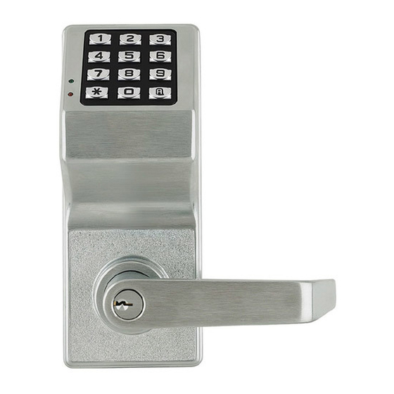
ArchiTech
Series
™
OI383A 09/16
PL6500
& ETPLN
PDL6500
&
ETPDLN
PDL6100
DL6100
1
Advertisement
Table of Contents


Need help?
Do you have a question about the ArchiTech Series and is the answer not in the manual?
Questions and answers