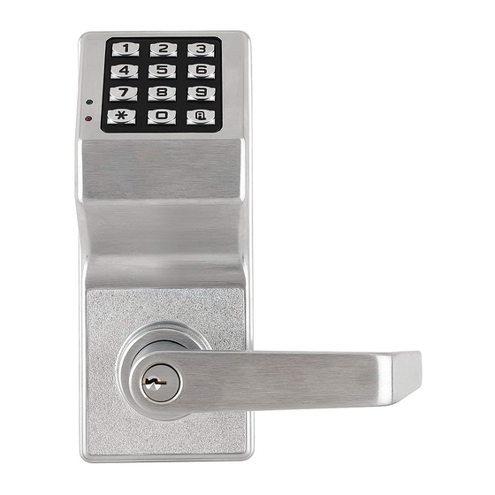
Alarm Lock DL6100 Wireless Trilogy Installation Instructions Manual
Hide thumbs
Also See for DL6100 Wireless Trilogy:
- Programming instructions manual (36 pages) ,
- User manual (60 pages)
Table of Contents
Advertisement
Wireless Trilogy
®
DL6100 & PDL6100 Door Locks
345 Bayview Avenue
Amityville, New York 11701
For Sales and Repairs 1-800-ALA-LOCK
Installation Instructions
For Technical Service 1-800-645-9440
Publicly traded on NASDAQ
Symbol: NSSC
© ALARM LOCK 2012
WI1674B 3/12
PDL6100
DL6100
with Proximity
Card Reader
Wireless Trilogy Series
Network Access Control Systems
PDL Series with ProxCard
Access
®
1
Advertisement
Table of Contents

Summary of Contents for Alarm Lock DL6100 Wireless Trilogy
-
Page 1: Installation Instructions
345 Bayview Avenue Amityville, New York 11701 For Sales and Repairs 1-800-ALA-LOCK Installation Instructions For Technical Service 1-800-645-9440 Publicly traded on NASDAQ Symbol: NSSC © ALARM LOCK 2012 WI1674B 3/12 PDL6100 DL6100 with Proximity Card Reader Wireless Trilogy Series Network Access Control Systems... -
Page 2: Table Of Contents
Ordering Information ............ 3 Install Interchangeable (IC) Cores ......8 Door Preparation ............4 Changing an Existing IC Core ........8 Alarm Lock Installation Jig .......... 4 Removing the IC Core and Lever ....... 9 Latch Installation ............4 Troubleshooting ............9 Strike Installation ............ -
Page 3: Wireless Lock Configuration Overview
WIRELESS LOCK CONFIGURATION OVERVIEW keypad programming--even before a wireless network is set up. PDL6100 & DL6100 ™ The Trilogy Networx PDL6100 and DL6100 series door locks Therefore, you can install the locks on the doors before configur- allow you to upload and download programming features wire- ing the wireless network, or you can set up the wireless network lessly using a computer connected to a computer network. -
Page 4: Door Preparation
While depressing the lever catch, pull off the lever (jiggle 1. If 2 1/8" hole already exists, use optional Alarm Lock In- lever if needed). stallation Jig to ensure accurate locating and drilling of... -
Page 5: Lock Installation
FIG. 5: INSERT LEVER RELEASE PIN TO DEPRESS THE LEVER CATCH 2. Depressing this lever catch also allows the inside hous- ing to be separated from the outside housing. Use a small screwdriver to depress the lever catch (the lever FIG. -
Page 6: To Reverse Lever Handing
For other door thicknesses, consult factory. the bent tabs facing door (the bent tabs bite into wooden doors, preventing their rotation; for metal doors, drill small holes to allow the rose plate to sit flush against door). Fasten with two 8-32 x 1 1/4 Phillips pan head TO REVERSE LEVER HANDING screws through the inside rose, engaging the outside lock body. - Page 7 motor cable notch without pinching or cutting the wire. 6. Plug the battery connector into its receptacle. See Fig. 17. Upon connection of the battery pack, you will hear 3. See Fig. 14. Before placing the inside housing onto the three beeps.
-
Page 8: Attaching Levers And Locksets
Set core aside. DOOR. 2. Insert Alarm Lock tailpiece with washer into new core. 3. Insert new control key into new core, turn clockwise. 4. Insert new core into lever and turn key counterclockwise INTERCHANGEABLE (IC) LOCKS to lock in position. -
Page 9: Removing The Ic Core And Lever
Unable to assemble outside lever. REMOVING THE IC CORE & LEVER • Key and tailpiece orientation are incorrect (See Fig. 21 1. Remove the existing primary or secondary IC core by and 22). inserting the control key, then turning the key clockwise and pulling the key to remove the core. -
Page 10: Erase All Programming
POWER UP FIRST TIME BATTERY REPLACEMENT • When applying power to the lock for the first time, When a valid code is entered and the batteries are stop and follow the procedure outlined in the Program- weak, the red LED will light when the keys are pressed ming Instructions (for the DL6100, see WI1820;... - Page 11 NOTES...
-
Page 12: Warranty
ALARM LOCK will, In no event shall ALARM LOCK be liable for an within said period, at its option, repair or replace any amount in excess of ALARM LOCK's original selling...


Need help?
Do you have a question about the DL6100 Wireless Trilogy and is the answer not in the manual?
Questions and answers