Table of Contents
Advertisement
®
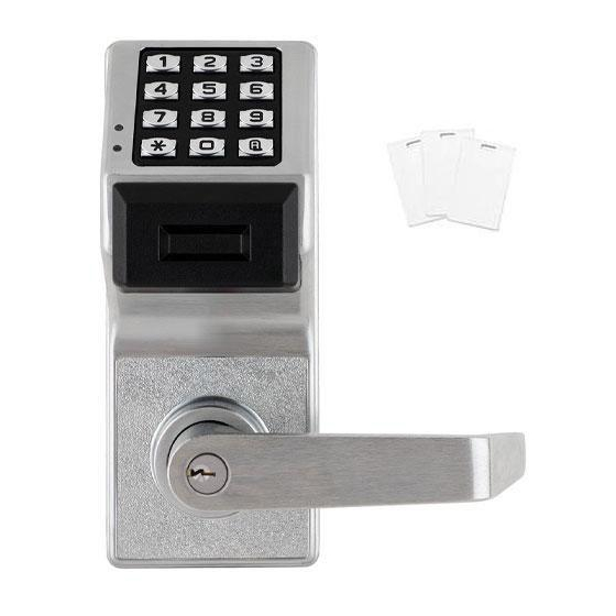
Wireless Trilogy
PDL6200 & PDL8200
With Door Monitoring
PDL8200 includes 13.56MHz Smart Card Support
345 Bayview Avenue Amityville, New York 11701
For Sales and Repairs 1-800-ALA-LOCK
For Technical Service 1-800-645-9440
Programming Instructions
or visit us at
http://tech.napcosecurity.com/
(Note: Technical Service is for security professionals only)
Publicly traded on NASDAQ
Symbol: NSSC
© ALARM LOCK 2016
WI2203 08/16
PROXIMITY KEYFOB
PROXIMITY CARD
13.56MHZ SMART
CARD
(PDL8200 ONLY)
AL-IME-USB
GATEWAY MODULE
PDL8200 / PDL6200
AL-IM2 SERIES
GATEWAY MODULES
DL-WINDOWS PROGRAMMING SOFTWARE
AL-IM2-80211
AL-IME2
AL-IME2POE
AL-IM2-PIE PLUG-IN
EXPANDER MODULE
1
Advertisement
Table of Contents

Related Manuals for Alarm Lock Wireless Trilogy PDL6200


Summary of Contents for Alarm Lock Wireless Trilogy PDL6200
- Page 1 For Technical Service 1-800-645-9440 Programming Instructions or visit us at http://tech.napcosecurity.com/ (Note: Technical Service is for security professionals only) Publicly traded on NASDAQ Symbol: NSSC © ALARM LOCK 2016 WI2203 08/16 PROXIMITY KEYFOB PROXIMITY CARD 13.56MHZ SMART CARD (PDL8200 ONLY)
-
Page 2: Table Of Contents
ETWORX LARM RILOGY ERIES TAND LONE AND ETWORK ROGRAMMABLE CCESS ONTROL YSTEM IS A SERIES OF TATE IRELESS AND EYPAD NTRY ROGRAMMABLE ECURITY OCKS PDL6200 & PDL8200 ™ The Trilogy Networx PDL6200 and PDL8200 proximity lock models are identical except the PDL8200 features a proximity reader that reads 13.56MHz proximity smart cards exclusively. -
Page 3: Lock Features
Networx lock in the system (see "How do the Emergency Commands work?" on page 8) Computer Programming Full Administrative programming from a PC using Alarm Lock's DL-Windows Software. For a description of all features, see the DL-Windows User's Guide (OI382) and the DL-Windows for Networx User's Guide (OI383) ... - Page 4 RJ-45 Ethernet cable. This model has one antenna used to transmit to the Networx series door lock via an Alarm Lock proprietary radio connection.. Ceiling- or wall-mountable. Powered with Class 2, 6VAC transformer (supplied).
-
Page 5: Supported Products And Applications
Ethernet socket is through the rear mounting plate. Important: DL-Windows version 5.3.2 or later is required to support version 2 Gateways and Expanders. Note: The AL-IME2-POE Gateway is compatible with Alarm Lock and Continental Access products. Refer to the documentation supplied with your soft- ware for integration details. -
Page 6: Lock Design Overview
Lock Design Overview Why use User Codes? With ordinary door locks, the need to make physical copies of metal keys and distributing them can be a huge organizational and financial task -- and what will you do if someone causes a security breach by accidentally losing their key? The answer lies in the advantage of "firmware". -
Page 7: Terminology Used In This Manual
Terminology Used in this Manual What is a Lock Program? gramming tasks the User is allowed (with Master allowing ALL tasks). A Lock Program contains the instructions that the lock uses to Note: Since the Programming Level is closely associated perform its various functions. - Page 8 User 298: Reserved Programs (programs that make the lock perform its many func- In previous versions of the ALARM LOCK Trilogy series locks, tions) add multiple Users (who have access), add proximity cards, User Number 298 initiated the sending of data to or from the retrieve event logs, and create Schedules.
-
Page 9: Programming Levels
Programming Levels The Programming Level defines the range of programming Supervisor: Always associated with Users 7, 8 and 9. tasks a User is allowed to perform. The higher the Level, the Can only program functions relating to day to day more programming tasks the User is allowed (with Master operation. -
Page 10: Conventions Used In This Manual
Conventions Used in this Manual Enabling/Disabling Users (By User Number) Minimum Required Program Level User Number must be between 2 and 5000. Program Levels are abbreviated as follows: NOTE: Will Enable/Disable users even if the user is associated with an enabled group. Function M = Master Description... -
Page 11: Emergency Commands
Emergency Commands Emergency Commands The PDL6200 and PDL8200 series locks can be programmed to send and/or respond to Emergency Commands ("Emergency Lockdown", "Emergency Passage" and " Return to Normal" ). Emergency Commands can be initiated directly from the lock's keypad, initiated from an RR-4BKEYFOB Wireless Remote Release or initiated from the Networx server running DL-Windows. - Page 12 Emergency Commands (cont'd) tures to customize your system. Example #1: DL-Windows by default enables (checks) all of the features, as shown above in the Features dialog. What will happen when all features are enabled and an "Emergency Lockdown" command is initiated at the keypad? Because the Activate Local Emergency commands are enabled, the lock that initiates the Emergency Command will lock, then this lock will inform the Gateway to broadcast the Emergency Command to all locks assigned to the same "Gateway Group".
-
Page 13: Wireless Remote Releases
Wireless Remote Releases Overview Two types of "Wireless Remote Release" devices are compatible with the PDL6200 and PDL8200: The RR-1BUTTON Wireless Remote Release Button (see WI1999) and RR-4BKEYFOB Wireless Re- mote Release Keyfob (see WI2004). Whether the Wireless Remote Release contains a single button (RR-1BUTTON) or four buttons (RR-4BKEYFOB), each button can be "paired"... -
Page 14: Wiring And Power Up
For models with a replacable battery pack, use Burglary Control Panel wiring. See page 31. four (4) C-size 1.5 volt alkaline batteries. For models with a sealed battery pack, contact your Alarm Lock dealer for a replacement battery pack. Always replace weak batteries as soon as possible. -
Page 15: Quick Start
Quick Start First Time Start Up 1. Unpack the lock. 2. With the batteries disconnected, hold down the ; key for 10 seconds and release. 3. Connect the batteries and listen for 3 beeps. Within 5 seconds of hearing the 3 beeps, press and hold ; until beeping starts. - Page 16 Quick Start (cont’d) Delete a User Code 1. Enter Program Mode (if not in already). 2. Press ; 2 ; User Number The sounder beeps for 10 seconds with green (and then red) LED flashes. At this point the lock expects a presentation of a proximity card;...
-
Page 17: Testing The Codes Entered
2. Press ; 2 ; _ :. (Enter the User Number matched to the proximity credential you want to delete). credential 3. Lock will beep continuously. Do not present ANY during this step. Wait until lock stops beeping, about 10 sec- onds. - Page 18 Programming Functions--Overview Function 48 Enable Passage Mode Function 1 Change Master Code See page 19 See page 25 Function 49 Disable Passage Mode See page 25 Function 2 Add/Delete/Change User Codes See page 19 Return Lock to Normal Passage Function 50 See page 25 Function 3 User Disable (By User Number)
-
Page 19: Programming Functions
Programming Functions USERS 1. New Master Code [ _ _ _ _ _ _ ] [ _ _ _ _ _ _ ] (User Number 1) (New Master Code) (Confirm New Master Code) Master Code must be 6 digits-only. ... - Page 20 Programming Functions (cont'd) USERS (Continued) User Enable/Disable (By User Number) User Number must be between 2 and 5000. NOTE: Will Enable/Disable Users even if the User is associated with an enabled Group. Use Function 3 to disable a specific User Number and their associated User Code.
- Page 21 Programming Functions (cont'd) CLEAR FUNCTIONS 12. Clear All Schedules and Timeout Functions ; 1 2 ; 0 0 0 : Function 12 clears all programmed Schedules and all Timeout Functions. (To clear All Timeout Functions only, see Function 13 below). Function 12 will clear all of the following: All Schedule Functions 72 through 93, Timeout Functions 5, 25 through 34 and Function 47.
- Page 22 Programming Functions (cont'd) NOTE: Clear All Timeout Functions by entering Function 13. GROUPS Group Enable/Disable with Timeout (Enter Timeout, XXX Hours) (Functions 25-34 are enabled through the keypad only) Hours must be between 001-999. Enter the functions below to Enable/Disable Groups for the amount of time entered in hours. NOTE: Only 4 Timeout Functions are allowed at any one time.
- Page 23 Programming Functions (cont'd) CLOCK SETTINGS 38. Set Date [ _ _ _ _ _ _ ] ; 3 8 (Date) Use Month Day Year format - MMDDYY - Single digit months and days are entered with a preceding zero. ...
- Page 24 Programming Functions (cont'd) CLOCK ADJUST Clock Adjust Number of seconds to adjust (speed up/slow down) the clock each day must be be- tween 0-55 seconds. Note: Repeated use of these Functions are not "cumulative" (this means, for exam- Clock Accuracy ple, if the clock has already been set to speed up 10 seconds per day, and then is The internal oscillator is factory calibrated to an accu- found to need an additional 10 seconds, then program 20 seconds using Function 43).
- Page 25 Programming Functions (cont'd) PERMANENT PASSAGE MODE Passage Mode Enable/Disable - Schedule will not Override Function 48 allows passage through the door without the need for a credential. Re-Lock using Function 49. Programmed Schedules will not override the state of the lock using functions 48 and 49. If it is required that programmed schedules override Passage Mode, Enable/Disable Passage Mode using Functions 45/46.
- Page 26 Programming Functions (cont'd) 55 - 59. Reserved LOCKOUT 60. Number of Attempts Before Lockout Number of attempts before lockout must be 1-9 attempts. The number of attempts is reduced by half every time the keypad is locked out without a successful code entry (default is 6 attempts).
- Page 27 Programming Functions (cont'd) [ _ _ ] ; 6 7 67. Add System Features (Event Number) Relay Features (For locks equipped with an internal relay) Use Function 67 to program one or more lock events and the relay will energize when the programmed event(s) listed below occurs.
- Page 28 Programming Functions (cont'd) [ _ _ ] ; 6 7 67. Add System Features (cont'd) (Event Number) 39. Users are Disabled During Lockdown. (Default = ON) † † Basic Users (User Numbers 12 - 5000) are denied ac- cess (passage through the door) during an Emergency. 43 Enable Sounder on Emergency.
- Page 29 Programming Functions (cont'd) Delete Relay Features / Door Ajar Trip Time Function 68 has two functions: Delete all Relay Features added by Function 67: Enter ; 6 8 ; 0 0 0 :. Door Ajar Trip Time: Program the number of seconds the Door Position Contacts may remain open without triggering a Door Ajar warning.
- Page 30 Programming Functions (cont'd) QUICK SCHEDULES Quick Schedules - Enable Group For your convenience, your lock comes pre-programmed with Quick Schedules, which, when programmed, enable Groups for popular blocks of time. Group members will be enabled during the blocks of time defined below, but will still need to enter their User Codes into the keypad to unlock the lock.
- Page 31 Programming Functions (cont'd) SCHEDULES GROUP 1 ACTIVATED Scheduled Relay Activation (Group 1 Activated) Functions 90 and 91 allow you to set up a window of time where if any Group 1 User Code is entered within this window, the relay (where equipped) will be activated for 2 seconds. This relay can be used with a Control Panel that has a key switch disarm option.
- Page 32 Programming Functions (cont'd) Scheduled Group 4 Enable (Group 1 Activated) Functions 92 and 93 allow you to set up a window of time where if any Group 1 User Code is entered within this window, Group 4 members will be enabled. (Group 4 members will still need to enter their User Codes to enter). For addi- tional information, see "Group 1 Activated Features"...
-
Page 33: Groups And Scheduled Group 1 Examples
The following examples detail the more advanced features of the PDL series locks. Although all features and device functions can be programmed using the lock keypad, when programming becomes more complex you may find it easier to use DL-Windows software to program your Alarm Lock security lock. - Page 34 Groups and Scheduled Group 1 Examples (cont'd.) Functions 90/91: Use Function 90 and 91 (see page 31) to create a window of time where if any Group 1 User Code is entered within the programmed window, the internal relay (where equipped) will be activated for 2 seconds. The relay can be configured to disarm a burglary control panel (see page 31).
-
Page 35: Programming Record Sheet
Default Values are shown in parentheses. Function Function Name Programming Number(s) 43/44 Clock Adjust 0-55 Seconds 52/53/54 Pass Time (3 sec) 10 sec 15 sec Set Lockout Attempts 1-9 Attempts Set Lockout Time 1-60 seconds 64/65 Remote Input Momentary (Enable) -
Page 36: User Code Record Sheet
User Number User Code Group User Name (1-5000) (3-6 digits) Association Note: For a complete list of user codes, obtain a printout from the DL-WINDOWS software. -
Page 37: Schedule Record Sheet
Day(s) Up to 500 scheduled functions can be programmed. For Day Enter : 1 = Sunday, 2 = Monday, 3 = Tuesday, 4 = Wednesday Function Number Time Function Name 5 = Thursday, 6 = Friday, 7 = Saturday, 8 = Monday through Friday, 9 = Saturday and Sunday, 0 = All days of the week Enter time of day in 24-hour format (00:00- 23:59) -
Page 38: Glossary
Glossary ACCESS = Entry into a restricted area. USER CODE = Code used by Users. Code is 3 AMBUSH = A special Code entered at the keypad to 6 numeric digits long, allowing controlled entry. when the User is forced to unlock a security device. ... -
Page 39: Guard Tour Code
Glossary (cont'd) from DL-Windows. In addition, the automatic place- Master, Installer, Manager and Supervisor) have ment of a new Gateway into an Emergency Group specific abilities to program and /or control the lock. allows for keypad-initiated Emergency Commands to LOCKOUT ATTEMPTS = A specified number of lock all the locks in an entire system from a single invalid User Code entries (1-9), that will disable the wireless lock. -
Page 40: Warranty
This warranty shall not apply to any equipment, or any part In no event shall ALARM LOCK be liable for an amount in thereof, which has been repaired by others, improperly excess of ALARM LOCK's original selling price of the...
Need help?
Do you have a question about the Wireless Trilogy PDL6200 and is the answer not in the manual?
Questions and answers