Advertisement
345 Bayview Avenue, Amityville, New York 11701
For Sales and Repairs 1-800-ALA-LOCK
For Technical Service 1-800-645-9440
or visit us at
http://tech.napcosecurity.com/
(Note: Technical Service is for security professionals only)
Publicly traded on NASDAQ
Symbol: NSSC
OVERVIEW
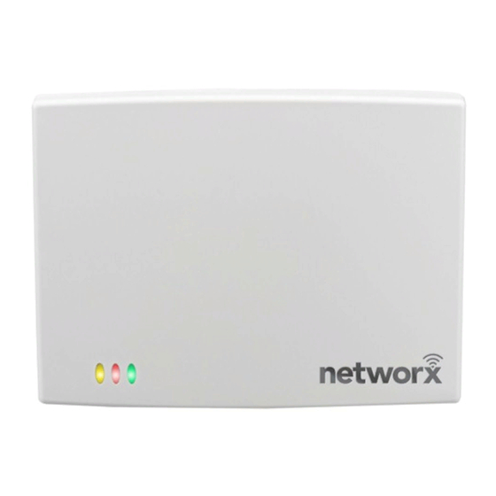
The AL-IME2-POE is a " Power Over Ethernet"
Gateway device used within the Trilogy Networx
wireless system. Installation is simple, with the AL-
IME2-POE only requiring access to one RJ-45
Ethernet network cable.
Version 2
The AL-IME2-POE " version 2" Gateways (notice the
"2" in the model name) are the next generation of Net-
worx Gateways. The "version 2" models are virtually
the same as the original "version 1" Gateways, but
have the added ability to expand your system with up
to 7 Expanders (model AL-IME2-EXP Expanders
cannot communicate with older "non-version 2" Gate-
ways). Note: Version 2 Gateways CAN be mixed into
an existing system that includes older "non-version 2"
Gateways.
IMPORTANT: DL-Windows version 5.4.2 or later is
required to support version 2 Gateways and Expand-
ers.
The AL-IME2-POE Gateway is compatible with
Alarm Lock and Continental Access products. Refer
to the documentation supplied with your software for
integration details.
Blue ID Card
We strongly recommend that when installing any mod-
el
Gateway,
a
Card" (OI357) be completed. Gateway physical loca-
tions may easily be forgotten. These ID cards may
prove very useful when replacing Gateways, when se-
lecting a particular Gateway to use to discover locks,
or whenever an installed Gateway needs to be physi-
cally located.
AL-IME2-POE SPECIFICATIONS
NETWORK RANGE
Gateway to Locks: Clear field range 500'.
Typical indoor range:
Networx 50 -125'.
Gateway / Expander to Expander: Clear field range
500'. Typical indoor range: 75-175'. Note: Actual
range varies with building construction.
AL-IME2-POE "Power Over Ethernet" Gateway
© ALARM LOCK 2017
" Gateway
blue-colored
Networx 75-175'; ArchiTech
Installation Instructions
AL RADIO LINK
900 MHz GFSK
™
50 Channels
10mW power output
POWER
- Installer should use a UL or ETL Listed POE injector or
a UL or ETL Listed POE switch.
POE Voltage: 48VDC Nominal
Input Voltage: 5 - 6VAC
ENVIRONMENTAL
Operating Temperature: -20˚ to 60˚C (-4˚ to 140˚F)
Storage Temperature: -40˚ to 85˚C (-40˚ to 185˚F)
PHYSICAL
Enclosure Size: 4.5"H x 6.0"W x 1.94"D
Weight: 0.5lbs.
The
TIP
Signal Meter tool can help you
perform a site survey test of the
premises to find the optimum
location for Gateways relative to
Networx locks; as well as determine the
optimum number of Gateways (or
Expanders) needed for signal area
coverage.
See WI2092 or speak to
your Alarm Lock sales representative
for more information.
ID
GATEWAY LOCATION GUIDELINES
Before selecting a final mounting location for your
Gateway, the following must be taken into considera-
tion:
Gateways should be located within 175 feet (radially)
from the intended wireless lock locations
Open areas will increase range while concrete
building construction, walls, ceilings and narrow
corridors will decrease range
ArchiTech series locks generally have shorter
range to/from a Gateway
Generally, the Gateway should be within approxi-
mately 75 feet (radially) from an AL-IME2-EXP Ex-
pander (see WI2156)
Select a location that allows access to an RJ-45 net-
work Ethernet cable connection
WI2152BLF 12/17
AL-NSM
Networx
1
Advertisement
Table of Contents

Summary of Contents for Alarm Lock AL-IME2-POE
- Page 1 Publicly traded on NASDAQ Symbol: NSSC OVERVIEW AL RADIO LINK 900 MHz GFSK The AL-IME2-POE is a " Power Over Ethernet" ™ 50 Channels Gateway device used within the Trilogy Networx 10mW power output wireless system. Installation is simple, with the AL- IME2-POE only requiring access to one RJ-45 Ethernet network cable.
-
Page 2: Mounting Instructions
CONNECTING TO A NETWORK MOUNTING INSTRUCTIONS The AL-IME2-POE Gateway requires a connection The AL-IME2-POE rear housing must be mounted from its Ethernet socket to a POE switch, router or in- "up" as shown on the page 7 template; i.e. when the jector using an RJ-45 cable (not a crossover cable). - Page 3 The "Expander Group" dial setting deter- work administrator and request the following: mines which Expanders are associated with which IP Address - An address for each Alarm Lock Gate- ● Gateway, thus preventing Gateways from discovering way device unintended Expanders. See WI2156 for more infor- Subnet Mask - Filtering data ("mask bits") as re-...
-
Page 4: Reset The Gateway
"selection "selection Connect RJ-45 / arrow" arrow" Apply Power Red LED ON (several seconds) Red LED blinks slowly Fig. 5. Example: The above Expander Group dials are set to "50" (searching for IP) All LEDs OFF (briefly) POWER UP Connect RJ-45 (POE) Ethernet cable to the Gateway. Upon connection, the Gateway automatically begins searching for a valid IP address from the network. - Page 5 GATEWAY LED INDICATIONS Receiver On (normal operation) Yellow Transmitter On (Gateway Status) Not configured - Rapid blinking / flickering Idle / configured - 1 blink per second Green Lock Communication Fail - 2 blinks (continuously) Expander Communication Fail - 4 blinks (continuously) CLOSE HOUSING COVER Close the housing cover by first engaging the hooks at...
- Page 6 NOTES...
- Page 7 AL-IME2-POE Mounting Template 4" 1-13/16" 3-9/32" 3-3/8"...
-
Page 8: Alarm Lock Limited Warranty
This warranty shall not apply to any equipment, or any part In no event shall ALARM LOCK be liable for an amount in thereof, which has been repaired by others, improperly excess of ALARM LOCK's original selling price of the...


Need help?
Do you have a question about the AL-IME2-POE and is the answer not in the manual?
Questions and answers