Table of Contents
Advertisement
Quick Links
Wireless Trilogy
®
DL6500 & ETDLN
345 Bayview Avenue
Amityville, New York 11701
Programming Instructions
For Sales and Repairs 1-800-ALA-LOCK
For Technical Service 1-800-645-9440
Publicly traded on NASDAQ
Symbol: NSSC
© ALARM LOCK 2011
WI1836A 09/11
DL6500 & ETDLN
AL-IM SERIES
GATEWAY MODULE
DL-WINDOWS PROGRAMMING
AL-IM80211
SOFTWARE
AL-IME
AL-IMEPOE
1
Advertisement
Table of Contents

Related Manuals for Alarm Lock DL6500


Summary of Contents for Alarm Lock DL6500
- Page 1 Wireless Trilogy ® DL6500 & ETDLN 345 Bayview Avenue Amityville, New York 11701 Programming Instructions For Sales and Repairs 1-800-ALA-LOCK For Technical Service 1-800-645-9440 Publicly traded on NASDAQ Symbol: NSSC © ALARM LOCK 2011 WI1836A 09/11 DL6500 & ETDLN AL-IM SERIES...
-
Page 2: Table Of Contents
OCKS DL6500 & ETDLN The DL6500 and ETDLN mortise locks are designed to allow all features to be pro- grammed either at the keypad or through its radio link to a DL-Windows equipped computer. In addition, Audit Log Data may be transmitted through the radio link back to the DL-Windows computer. -
Page 3: Lock Features
Guard Tour Code (see page 7) • Emergency Commands (see page 7) Keypad and Computer Programming • All programming may be performed manually from the keypad, or from a PC using Alarm Lock's DL- Windows Software (see page 7) ® ® ®... -
Page 4: Supported Products
Hardwired Gateway Interface Module, supports up to 63 Networx Locks, connects directly to a network using a standard RJ-45 Ethernet cable. This model has one antenna used to transmit to the DL6500 / ETDLN via an Alarm Lock proprietary radio connection.. -
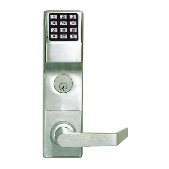
Page 5: Lock Design Overview
Preparing to Program User Codes The DL6500 / ETDLN keypad contains 12 buttons, numbers 1 through 9 plus zero, a star button (:) and a special "AL" button (;). You can use the DL6500 / ETDLN keypad to program your system, or you can use a computer program called DL- Windows that can be configured to program your system wirelessly. -
Page 6: Terminology Used In This Manual
The Lock Program is essentially a computer database file that maintains feature settings, schedules, audit trails, etc. Us- For example, DL6500 / ETDLN Series locks can hold up to 5000 ing DL-Windows, a Lock Program (called a "Lock Profile" in DL-... - Page 7 (it is a "non-pass" code) and therefore does not allow passage How do the Emergency Commands work? through the door. See "User 299: Guard Tour Code" below. For use with all DL6500 / ETDLN Series locks enrolled into the ™ Trilogy Networx...
-
Page 8: Programming Levels
Type”. longer requiring (or allowing) the use of this AL-IR1 printer, For example, DL6500 / ETDLN Series locks can hold up to 5000 Print Only Users are also no longer required. Although the Users in its programming memory, and each User is associ- attributes of User Numbers 10 and 11 have been changed ated with a User Number (see definition of "User Number"... -
Page 9: Conventions Used In This Manual
All program sequences are followed by the : key; 2 short beeps indicate a successful program sequence. LED and Sounder Indicators The DL6500 / ETDLN Series locks provide visual and audible keypad feedback. With a fully charged battery, the LED and sounder feedback is as follows:... -
Page 10: Wiring And Power Up
Time. For models with a replacable battery pack, use four (4) C-size 1.5 volt alkaline batteries. For models with a FIRST TIME sealed battery pack, contact your Alarm Lock dealer for a • When applying power to the lock for the first time, replacement battery pack. -
Page 11: Quick Start
Quick Start First Time Start Up 1. Unpack the lock. 2. With the batteries disconnected, hold down the ; key for 10 seconds and release. 3. Connect the batteries and listen for 3 beeps. Within 5 seconds of hearing the 3 beeps, press and hold ; until beeping starts. - Page 12 If you wish to re-enter Program Mode, key-in your new 6-digit Master Code, and press ;. You are now ready to mount and install your DL6500 / ETDLN Series locks and give out your User Codes. Before installation, it is suggested you test and verify that all User Codes entered are active (see next page).
-
Page 13: Testing The Codes Entered
Testing the Codes Entered Verifying Basic Keypad User Codes Test a valid User Code: VALID CODE - The Green LED will flash momentarily and the sounder will beep a few times after a valid code is entered. INVALID CODE - The RED LED will flash several times and the sounder will beep several times after an invalid code is entered. Use Function 2 to re-program the code. -
Page 14: Programming Functions Overview
Programming Functions--Overview See page 21 Function 1 Change Master Code See page 15 Function 48 Enable Passage Mode See page 21 Function 49 Disable Passage Mode Function 2 Add/Delete/Change User Codes See page 15 Return Lock to Normal Passage Function 50 See page 21 Function 3 User Disable (By User Number) -
Page 15: Programming Functions
User Code, you can control access to the lock by adding or deleting User Codes. See "Terminology Used in this Manual" on page 6 for more information. Lock Defaults for DL6500 / ETDLN Series locks Users added will default to a Group Association and a Programming Level ability as follows:... - Page 16 Programming Functions (cont'd) USERS (Continued) User Enable/Disable (By User Number) • User Number must be between 2 and 5000. NOTE: Will Enable/Disable Users even if the User is associated with an enabled Group. Use Feature 3 to disable a specific User Number and their associated User Code.
- Page 17 Programming Functions (cont'd) CLEAR FUNCTIONS 12. Clear All Schedules and Timeout Functions ; 1 2 ; 0 0 0 : Function 12 clears all programmed Schedules and all Timeout Functions. (To clear All Timeout Functions only, see Function 13 below). Function 12 will clear all of the following: All Schedule Functions 72 through 93, Timeout Functions 5, 25 through 34 and Function 47.
- Page 18 Programming Functions (cont'd) NOTE: Clear All Timeout Functions by entering Function 13. GROUPS Group Enable/Disable with Timeout (Enter Timeout, XXX Hours) (Functions 25-34 are enabled through the keypad only) • Hours must be between 001-999. Enter the functions below to Enable/Disable Groups for the amount of time entered in hours. NOTE: Only 4 Timeout Functions are allowed at any one time.
- Page 19 Programming Functions (cont'd) CLOCK SETTINGS 38. Set Date [ _ _ _ _ _ _ ] ; 3 8 (Date) • Use Month Day Year format - MMDDYY - Single digit months and days are entered with a preceding zero. •...
- Page 20 Programming Functions (cont'd) CLOCK ADJUST Clock Adjust Number of seconds to adjust (speed up/slow down) the clock each day must be be- tween 0-55 seconds. Note: Repeated use of these Functions are not "cumulative" (this means, for exam- Clock Accuracy ple, if the clock has already been set to speed up 10 seconds per day, and then is The internal oscillator is factory calibrated to an accu- found to need an additional 10 seconds, then program 20 seconds using Function 43).
- Page 21 Programming Functions (cont'd) PERMANENT PASSAGE MODE Passage Mode Enable/Disable - Schedule will not Override • Function 48 allows passage through the door without the need for a User Code. Re-Lock using Function 49. • Programmed Schedules will not override the state of the lock using functions 48 and 49. If it is required that programmed schedules override Passage Mode, Enable/Disable Passage Mode using Functions 45/46.
- Page 22 Programming Functions (cont'd) 55 - 59. Reserved LOCKOUT 60. Number of Attempts Before Lockout • Number of attempts before lockout must be 1-9 attempts. • The number of attempts is reduced by half every time the keypad is locked out without a successful code entry (default is 6 attempts).
- Page 23 Programming Functions (cont'd) SYSTEM FEATURES [ _ _ ] ; 6 7 67. Add System Features (Event Number) • Internal Relay Features (12-23. Reserved) Use Function 67 to program one or more lock events and the Relay will energize when the programmed event(s) listed below oc- curs.
- Page 24 Programming Functions (cont'd) ENTER KEY Enter Key • When this function is enabled, the User must press after any valid User Code entry. Therefore, this Function allows User Codes to be subsets of other User Codes. Examples: 1 2 3 : can be a valid user code; 1 2 3 4 : a valid user code within the same lock.
- Page 25 Programming Functions (cont'd) QUICK SCHEDULES Quick Schedules - Enable Group For your convenience, your lock comes pre-programmed with Quick Schedules, which, when programmed, enable Groups for popular blocks of time. Group members will be enabled during the blocks of time defined below, but will still need to enter their User Codes into the keypad to unlock the lock.
- Page 26 Programming Functions (cont'd) SCHEDULES GROUP 1 ACTIVATED Scheduled Relay Activation (Group 1 Activated) Functions 90 and 91 allow you to set up a window of time where if any Group 1 User Code is entered within this window, the relay will be activated for 2 seconds. This relay can be used with a Control Panel that has a key switch disarm option. For additional information, see "Group 1 Activated Features"...
- Page 27 Programming Functions (cont'd) Scheduled Group 4 Enable (Group 1 Activated) Functions 92 and 93 allow you to set up a window of time where if any Group 1 User Code is entered within this window, Group 4 members will be enabled. (Group 4 members will still need to enter their User Codes to enter). For additional in- formation, see "Group 1 Activated Features"...
-
Page 28: Groups And Scheduled Group 1 Examples
Groups and Scheduled Group 1 Examples The following examples detail the more advanced features of the DL6500 / ETDLN Series locks. Although all features and device functions can be programmed using the lock keypad, when programming becomes more complex you may find it easier to use DL-Windows software to program your Alarm Lock security lock. - Page 29 Groups and Scheduled Group 1 Examples (cont'd.) Functions 90/91: Use Function 90 and 91 (see page 26) to create a window of time where if any Group 1 User Code is entered within the programmed window, a Relay will be activated for 2 seconds. The Relay can be configured to disarm a burglary control panel. See page 26. 1.
-
Page 30: Programming Record Sheet
Default Values are shown in parentheses. Function Function Name Programming Number(s) 43/44 Clock Adjust 0-55 Seconds 52/53/54 Pass Time (3 sec) 10 sec 15 sec Set Lockout Attempts 1-9 Attempts Set Lockout Time 1-60 seconds 64/65 Remote Input Momentary (Enable) Disable Ambush Code 00-99... -
Page 31: User Code Record Sheet
User Number User Code Group User Name (1-5000) (3-6 digits) Association Note: For a complete list of user codes, obtain a printout from the DL-WINDOWS software. - Page 32 User Number User Code Group User Name (1-5000) (3-6 digits) Association Note: For a complete list of user codes, obtain a printout from the DL-WINDOWS software.
-
Page 33: Schedule Record Sheet
Day(s) Up to 500 scheduled functions can be programmed. For Day Enter : 1 = Sunday, 2 = Monday, 3 = Tuesday, 4 = Wednesday Function Number Time Function Name 5 = Thursday, 6 = Friday, 7 = Saturday, 8 = Monday through Friday, 9 = Saturday and Sunday, 0 = All days of the week Enter time of day in 24-hour format (00:00- 23:59) - Page 34 Day(s) Up to 500 scheduled functions can be programmed. For Day Enter : 1 = Sunday, 2 = Monday, 3 = Tuesday, 4 = Wednesday Function Number Time Function Name 5 = Thursday, 6 = Friday, 7 = Saturday, 8 = Monday through Friday, 9 = Saturday and Sunday, 0 = All days of the week Enter time of day in 24-hour format (00:00- 23:59)
-
Page 35: Glossary
Glossary ACCESS = Entry into a restricted area. DEFAULT = Default settings are the original settings that were set at the factory; in other words, it is the lock's origi- AMBUSH = A special Code entered at the keypad when the nal factory condition when the lock was first taken out of User is forced to unlock a security device. -
Page 36: Warranty
24 months following the date of manufacture. In no event shall ALARM LOCK be liable for an amount in excess ALARM LOCK will, within said period, at its option, repair or replace...
Need help?
Do you have a question about the DL6500 and is the answer not in the manual?
Questions and answers