Advertisement
Quick Links
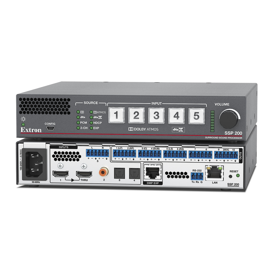
SSP 200 • Setup Guide
The Extron SSP 200 is a high-performance surround sound processor that automatically decodes Dolby
formats from digital input sources to discrete audio outputs. Providing up to ten built-in balanced analog outputs, the SSP 200
provides the flexibility needed for pro A/V applications in corporate, commercial, and education environments. It supports
the latest immersive formats of Dolby Atmos and DTS:X plus legacy Dolby and DTS formats. An upmix function synthesizes
exceptional multichannel audio from stereo content. The SSP 200 features an HDMI input with loop through, coaxial and optical
digital inputs, and an analog stereo input. It is designed for integration into pro A/V installations, featuring a compact, half-rack
metal enclosure, RS-232 serial and LAN control, and balanced line level outputs.
This guide provides instructions for an experienced user to set up and configure the SSP 200. It covers how to connect
CONFIG
other devices and perform basic operations using rear panel connections and the front panel controls. For full operation and
e
configuration through Extron Product Configuration Software (PCS), internal web pages, and Simple Instruction Set (SIS™)
commands, see the SSP 200 User Guide.
NOTE:
For information while using PCS, see the SSP 200 PCS Help File.
A A A
B B B
Rear Panel Connectors
INPUTS
1
50-60 Hz
A A A
Figure 1.
Rear Panel Connectors
A
AC power connector
B
Audio inputs
C
DMP expansion port
The SSP 200 (
A
) uses an IEC power cable to connect to a 100-240 VAC, 50-60 Hz, power source.
B
The SSP 200 (
) accepts one HDMI input with embedded audio, three digital inputs, and one analog input. In addition, there is
an HDMI loop out (through) connector.
•
Input 1 accepts digital signals through an HDMI cable, supporting HDMI version 2.0 with HDCP version 2.3 compliance.
•
Input 2 accepts a 75 ohm unbalanced digital coaxial S/PDIF input.
•
Inputs 3 and 4 accept digital signals through S/PDIF optical (TOSLINK
•
Input 5 accepts a balanced or unbalanced, stereo or mono, analog input through a 6-pole captive screw connector.
Connect an EXP-enabled device to the DMP expansion port (
Use the included one-foot long shielded CAT6 cable to connect the SSP 200 to a Primary EXP-enabled device (see the SSP 200
User Guide for EXP bus operation details).
H
The ten outputs (
) are balanced or unbalanced, line level, analog signals made available through captive screw connectors
providing outputs for the following surround sound channels.
Number
Abbreviation
1
LF
2
RF
3
C
4
SUB
5
LS
NOTE:
Numbers 7 through 10 are configurable as back, height, or downmix channels using PCS.
By default, the SSP 200 is set to 7.1 with downmix enabled with all ten analog outputs enabled. Outputs in this configuration are
7 – Left Back, 8 – Right Back, 9 – Downmix Left, and 10 – Downmix Right.
SOURCE
1
2
ATMOS
PCM
HDCP
2-CH
EXP
C C C
L
R
1(LF)
2(RF)
3(C)
5
THRU
2
3
4
B B B
D
RS-232 port
E
LAN port
F
Reset button
Channel Description
Left front
Right front
Center
Subwoofer
Left surround
INPUT
3
4
5
SURROUND SOUND PROCESSOR
D D D
H H H
4(SUB)
5(LS)
6(RS)
7
8
RS-232
Tx Rx G
LAN
DMP EXP
C C C
D D D
E E E F F F G G G
G
H
) cables.
®
C
) for a digital audio connection using Extron proprietary protocol.
Number
Abbreviation
6
RS
7
See note below
8
See note below
9
See note below
10
See note below
®
®
, DTS
, and PCM
VOLUME
SSP 200
E E E
9
(MIX)
10
RESET
SSP 200
Status light
Analog outputs
Channel Description
Right surround
1
Advertisement

Related Manuals for Extron electronics SSP 200


Summary of Contents for Extron electronics SSP 200
- Page 1 Numbers 7 through 10 are configurable as back, height, or downmix channels using PCS. By default, the SSP 200 is set to 7.1 with downmix enabled with all ten analog outputs enabled. Outputs in this configuration are 7 – Left Back, 8 – Right Back, 9 – Downmix Left, and 10 – Downmix Right.
- Page 2 Turn off or disconnect all equipment power sources. Mount the SSP 200 using optional rack and under-furniture mounting kits (available at www.extron.com), or place on a table using the provided rubber feet. The SSP 200 is housed in a 1U-high, 8.5 inch deep, half-rack wide enclosure.
- Page 3 3(C) 4(SUB) 5(LS) 6(RS) (MIX) Status LED — This LED indicates the current power and boot status of the SSP 200. It lights solid green when operational and solid amber during bootup and reset. RESET RS-232 THRU Tx Rx G...
- Page 4 To configure the SSP 200 with SIS commands via an RS-232, USB, or Ethernet connection, use the Extron DataViewer utility or a control system to send and receive SIS commands. For a list of SIS commands and variables, see the SSP 200 User Guide at www.extron.com.
Need help?
Do you have a question about the SSP 200 and is the answer not in the manual?
Questions and answers