
Related Manuals for Elitech FreezePoint 6000 Series

Summary of Contents for Elitech FreezePoint 6000 Series
- Page 1 FreezePoint ® Freezing Point Osmometer MODEL 6000, 6000P, 6000S, 6000SP USER’S MANUAL...
- Page 3 FREEZEPOINT ® Freezing Point Osmometer MODEL 6000, 6000P, 6000S, 6000SP USER’S MANUAL 57-0022-01-C (Last update 02/01/21)
- Page 4 ©2021 ELITechGroup Inc. All rights reserved. Printed in the United States of America. No part of this publication may be reproduced, transmitted, transcribed, stored in a retrieval system, or translated into any language (human or computer) in any form, or by any means whatsoever, without the prior express written permission of ELITechGroup Inc. FreezePoint is a trademark of ELITechGroup Inc.
- Page 5 This manual allows for the safe and efficient operation of the FreezePoint Model 6000 Freezing Point ® Osmometer (hereafter “device”). This manual is part of the device and must be stored in the immediate vicinity of the device and be easily accessible to personnel at any time. Personnel must carefully read and understand this manual before beginning any kind of work.
-
Page 6: Table Of Contents
Table of Contents Section 1: Safety 1.1 Explanation of symbols Safety notices Special safety notices Safety notices in instructions Additional identifiers 1.2 Intended use Intended use Attention when using device 1.3 Additional hazards Hazards due to electrical current Risk of infection Risk of injury Risks of device damage Repeatability of the measurement... - Page 7 Set date format 5.5 Measurement series name Set measurement series name 5.6 Result Unit Set result unit Section 6: Operation 6.1 Information before operation Electrical current Risk of infection 6.2 Power up device 6.3 Modify user preferences 6.4 Measure individual/batch samples 6.5 Calibrate device Calibration methods Calibrate device...
- Page 8 Appendix C: Contacting ELITechGroup Appendix D: Theory of Operation Appendix E: Operational Use General operating conditions Operational use Operation Defrosting procedure Safety Testing Installation, Operation, and Performance Qualification Product Information Table of Contents Urgent Safety Information Scope Instructions Installation Qualification (IQ) Verification Installation of the Instrument Ancillary Information Device Environment Operation (OQ) &...
-
Page 9: Section 1: Safety
Section 1: Safety 1.1 Explanation of symbols Safety notices The safety notices in this manual are identified by symbols. The safety notices are preceded by signal words indicating the degree of hazard. DANGER! This combination of symbol and signal word indicates an immediate dangerous situation that will result in death or serious injury if not avoided. -
Page 10: Special Safety Notices
Section 1: Safety Special safety notices Safety notices use the following symbols to indicate special hazards: WARNING! This combination of symbol and signal word indicates a potentially dangerous situation that may result in contamination with bio-hazardous materials. Observe the current Ordinance on Biological Substances and refer to the lab protocol. DANGER! This combination of symbol and signal word indicates an immediate dangerous situation due to electrical current. -
Page 11: Intended Use
Section 1: Safety 1.2 Intended use Intended use FreezePoint 6000 series osmometers are intended for laboratory use by qualified personnel for the ® determination of total osmolality of aqueous solutions. Attention when using device • Only use the device to measure aqueous solutions. •... -
Page 12: Additional Hazards
Section 1: Safety 1.3 Additional hazards Hazards due to electrical current DANGER! Risk of death due to electrical current on device! • Class I devices must be connected to a power socket with protective ground wire. • If the power or device connector is used as a separation device, the connector must be easily accessible at all times. -
Page 13: Risks Of Device Damage
Section 1: Safety Risks of device damage Exposure to liquids and moisture WARNING! Device damage due to exposure to liquids and moisture! Exposure to liquids and moisture can cause damage to the electrical components of the device, e.g. due to a short circuit. -
Page 14: Repeatability Of The Measurement
Section 1: Safety Repeatability of the measurement Incorrect measurement vessels NOTE! Impaired repeatability of measurement due to incorrect measurement vessels! Repeated use of the measurement vessels and use of incorrect consumables cannot guarantee reproducible measurement results. • Always use a clean and unused measurement vessel for every measurement. •... -
Page 15: Personal Requirements
Section 1: Safety 1.4 Personal requirements WARNING! Risk of injury due to inadequately qualified personnel! Work performed on the device by unqualified personnel or the presence of unqualified personnel in the hazard zone of the device creates risks that can result in serious injury and substantial property damage. •... -
Page 16: Personal Safety Gear
Section 1: Safety 1.5 Personal safety gear While performing the different tasks on and with the device, personnel must wear the personal safety gear referenced explicitly in the various sections of this manual. Description of personal safety gear The personal safety gear is explained below: Disposable lab gloves Disposable lab gloves protect the hands from touching sample residue. -
Page 17: Environmental Information
Section 1: Safety 1.6 Environmental Information NOTE! Danger to environment due to incorrect handling of handling of environmentally hazardous substances! Incorrect handling of environmentally hazardous substances, in particular incorrect disposal, can result in significant harm to the environment. • Always observe the warnings regarding the handling of environmentally hazardous substances and their disposal below. -
Page 18: Section 2: Design And Function
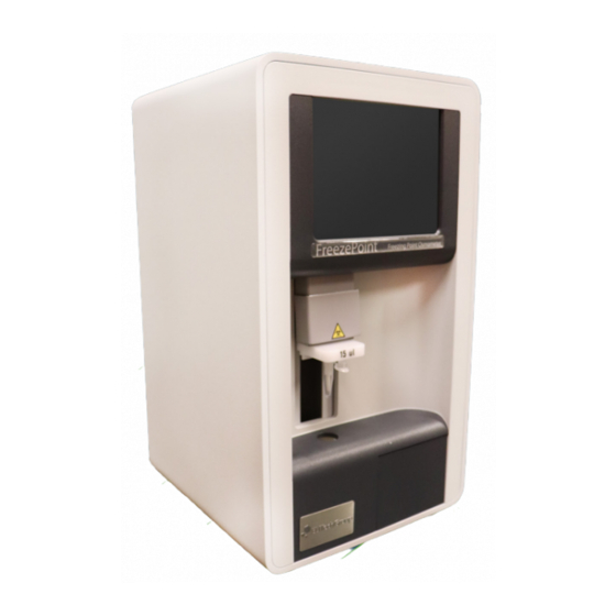
Section 2: Design and Function 2.1 Device Overview Figure 1 Device overview—front 1. Touchscreen page 25 2. Upper cooling system (behind movable elevator cover), page 24 3. Thermistor probe with measurement vessel, page 24 4. Lower cooling system page 24 5. - Page 19 Section 2: Design and Function Figure 2 Device overview-rear 1. Interfaces 2. Micro-Fuse compartment 3. On/Off switch 4. Power cable connection 5. Fan outlet...
-
Page 20: Standard Consumables
Section 2: Design and Function Standard Consumables NOTE: Risk of falsified measurement results! When using accessories and/or consumables provided by manufacturers other than ELITechGroup, the repeatability of the measurement results cannot be guaranteed. • Always use the accessories and consumables supplied by ELITechGroup. •... -
Page 21: Standard Items
Section 2: Design and Function Standard Items Figure 4 Overview of items Description Item Number 1. Blow-Out Device, FreezePoint (Pack of 10) AC-198 ® 2. Pipette, MLA, 15uL / 50 ul, D-Tipper Silver, Fixed Volume AC-199 / AC-201 3. Micro-Fuse, Slow-Blow, 1.6A FreezePoint (Pack of 2) RP-547 ®... -
Page 22: Measuring Method Basics
Section 2: Design and Function 2.2 Measuring Method Basics Osmolality The device measures the total osmolality of any aqueous solution. The osmolality of a solution is defined as the number (or amount of substance) of the osmotically active particles (e.g. salt ions, sugar, urea, proteins) present per kilogram of solvent (water). The osmolality is specified in Osmol/kg or mOsmol/kg. -
Page 23: Measurement Equipment
Section 2: Design and Function 2.3 Measurement Equipment Figure 5 Overview of measurement equipment 1. Elevator 2. Upper cooling system (behind movable elevator cover) 3. Handle for lowering the thermistor probe 4. Thermistor probe 5. Lower cooling system 6. Cover 7. -
Page 24: Upper Cooling System
Section 2: Design and Function Upper Cooling System 1. Initiation needle 2. Cooling pin The initiation needle (1) of the upper cooling system “seeds” the sample with ice crystals (“crystallization”). This causes the sample to freeze and heat up to its freezing point. -
Page 25: Touchscreen
Section 2: Design and Function 2.4 Touchscreen Figure 8 Overview of touchscreen The device is controlled using the touchscreen (1) WARNING! Property damage due to incorrect operation! The touchscreen can be damaged by sharp or hard objects or excessive pressure force. •... -
Page 26: Enter Values
Section 2: Design and Function Enter values Some menus are protected by a pin. Access to these menus is limited to the lab supervisor or authorized service personnel. Figure 9 1. To enter values, tap the corresponding entry field in the opened menu. This opens an on-screen keyboard. -
Page 27: Printer (Model 6000 P/Sp)
Section 2: Design and Function 2.5 Printer (Model 6000 P/SP) With built-in printer (only Models 6000 P/SP) 1. Opening for the printer paper 2. Printer pull-out handle The printer is used to print the measurement results. Rolls of printer paper are included with the delivery. -
Page 28: Connections And Interfaces
Section 2: Design and Function 2.6 Connections and interfaces The following connections and interfaces are located at the rear of the device: Figure 11 Connections and interfaces 1. COM1 (only for connecting barcode reader) 2. COM2 interface (RS-232 output) 3. USB port 4. -
Page 29: Interface Configuration
Section 2: Design and Function Interface configuration COM1 data port The upper COM1 (RS232) serial data port is used to connect a barcode reader. The barcode reader is configured at the factory and can be purchased from ELITechGroup. WARNING! Incompatible barcode reader! The use of a barcode reader other than the barcode reader supplied by ELITechGroup is not recommended because potential incompatibilities cannot be ruled out. -
Page 30: Log Formats
Section 2: Design and Function Log formats To set the data format used by the device, select Settings Lab Options Log Format from the menu. The following options are available: Line ending CRLF: Selecting this option places a carriage return (CR) and line feed (LF) at the end of the line. -
Page 31: Csv Format
Section 2: Design and Function CSV format If CSV format is selected, the log is displayed line by line. Each line is separated by the selected end of line symbol. Line content There are three types of line content Type Purpose Intro Message showing version numbers of device software. -
Page 32: Xml Format
Section 2: Design and Function Result line After each measurement a result line is sent which contains the following semicolon-separated values in a fixed order: Column Description batch Batch identifier in quotation marks, entered by the user or a sequential number generated automatically. - Page 33 Section 2: Design and Function Ticket A ticket consists of an XML tag which corresponds to one published ticket. If it relates to a single measurement, it contains an additional XML tag called “Measurement”, which contains the measurement and the associated metadata. If it relates to a batch measurement, one ticket may contain several measurements.
- Page 34 Section 2: Design and Function Example of a single measurement In the case of a single measurement the entire ticket is published in one piece when the measurement has been completed, the value BatchId does not apply. <Ticket class=”SAMPLE” serialno=”300201103” versions=”FP6000;Main:VX. XX;COM:VX.X;D:VX.XX;TEC:VX.X”>⏎...
- Page 35 Section 2: Design and Function Error messages The following error messages may be used to diagnose an operating error or device failure: Notification Meaning ABORT User cancels by pressing the EXIT key. LIFT User cancels by lifting the sensor. CANTCOOL Failed to sufficiently cool down sample.
-
Page 36: Section 3: Delivery, Packaging, And Storage
Section 3: Delivery, packaging, and storage Delivery condition 1 package containing the following components: • Device with protective sleeve (1) • Blow-out device (2) • Adjustment tool (3) • Micro-Fuse, Slow-Blow, 1.6A FreezePoint - 2 pack (4) ® • Pipette (5) •... -
Page 37: Packaging
Section 3: Delivery, packaging, and storage 3.1 Packaging About the packaging The package is packaged according to the expected transport conditions. Only environmentally friendly materials were used for the packaging. The packaging is intended to protect the device from transport damage and other damage until the time of installation. - Page 38 Section 3: Delivery, packaging, and storage Item number Item number. Batch ID Batch ID of the calibration standard. Biological safety Biological safety (month, year). Date until which the calibration standard fulfills its original function if stored properly. Bio-hazard Bio-contamination warning: Use care when operating upper cooling system and initiation needle.
-
Page 39: Unpacking And Device Storage
Section 3: Delivery, packaging, and storage 3.2 Unpacking and Device Storage Unpacking device 1. Carefully open cardboard box using a knife. 2. Remove device from packaging and place in a suitable location. 3. Keep packaging for possible later return. 4. After device has been shipped, please align the thermistor probe upon receiving, as it can become misaligned in transit and could cause inaccurate readings ( “Align the Thermistor probe”... -
Page 40: Section 4: Installation
Section 4: Installation 4.1 Transport device inside lab Personnel: User Safety gear: • Disposable lab gloves 1. Power down device using on/off switch on rear side and disconnect power plug. 2. Position a measurement vessel on the thermistor probe. NOTE! The measurement vessel is securely attached to the thermistor probe when it clicks into place. -
Page 41: Install Device
Section 4: Installation 4.2 Install device Personnel: User Safety gear: • Disposable lab gloves 1. Install device at installation site. Keep fan outlet on device clear. Keep fan outlet openings underneath device clear. Figure 18 Fan outlet WARNING! Risk of property damage! Only install device indoors. -
Page 42: Connect Device
Section 4: Installation 2. Remove protective sleeve from device. Figure 19 Remove protective sleeve 3. Remove transport safety device from thermistor probe. Proceed as follows: Figure 20 Transport safety device 4. Carefully pull transport safety device down and pull forward to remove. Figure 21 Remove transport safety device Connect device 1. -
Page 43: Section 5: Setup
Section 5: Setup Personnel: Lab supervisor 1. Complete all activities for installation and connection of the device. 2. Verify that the connections at the rear side of the device are secure. 3. Check the elevator for ease of movement. If necessary, grease the elevator guide ( “8.5 Lubricate elevator”... -
Page 44: Check Free Movement Of Steel Needle
Section 5: Setup 5.2 Check free movement of steel needle 1. Check initiation needle for free movement. Open the Adjust Needle menu (Start menu Settings Lab Options Maintenance Adjust Needle). CAUTION! Risk of injury from initiation needle! The tip of the initiation needle is exposed. Movement of the initiation needle can cause needle puncture injuries. -
Page 45: Set Calibration Defaults
Section 5: Setup 5.3 Set calibration defaults Select calibration procedure 1. Open the menu for configuring the lab options. In the Start menu, tap Settings Lab Options. NOTE! The menu can be protected with a lab supervisor pin. See QA Settings to learn more about calibration settings. Figure 25 Lab Options menu 2. -
Page 46: Select Calibration Standards
Section 5: Setup Select calibration standards Specify the allowed calibration points. They should be close to the expected measurement values. A calibration point (Custom) can be freely selected by the user in increments of 10 and enabled or disabled for selection. Enter the values in mOsmol/kg. -
Page 47: Date Time
Section 5: Setup 5.4 Date Time Set date and time 1. Enter date and time as follows: DD – Day, two digits [01…31] MM – Month, two digits [01…12] YYYY – Year, four digits [2020] HH – Hour, two digits [00…23] MM –... -
Page 48: Measurement Series Name
Section 5: Setup 5.5 Measurement series name Set measurement series name 1. Select the name for your measurement series. Figure 32 Measurement series name 5.6 Result Unit Set result unit 2. Select the unit for the measurement results: ◊ mOsmol/kg ◊... -
Page 49: Section 6: Operation
Section 6: Operation 6.1 Information before operation Electrical current DANGER! Risk of death due to electrical current on device! Contact with energized parts of the device results in immediate risk of death due to electric shock. Damage to the insulation of individual components can cause risk of death. •... -
Page 50: Power Up Device
Section 6: Operation 6.2 Power up device Personnel: User Safety gear: • Disposable lab gloves 1. Power up device on rear side using on/off switch. Figure 34 Power up device... -
Page 51: Modify User Preferences
Section 6: Operation 6.3 Modify user preferences Configure language Tap Language and select a language. Figure 35 Select language Overview Tapping Settings on the Start menu opens the Settings menu. The Settings menu lets the user configure the following settings: •... - Page 52 Section 6: Operation Configure screen saver 1. Select the duration after which the system activates the screen saver. Tapping OFF will deactivate the screen saver. Figure 38 Configure screen saver Activate paper feed (Models 6000P/SP) 1. Tap Paper Feed. The paper feed of the printer is activated briefly. Tap Back to exit the menu.
- Page 53 Section 6: Operation Laboratory options Tapping Lab Options in the Settings menu opens the Lab Options menu. The Lab Options option is protected with the lab supervisor pin Figure 41 Overview of lab settings The Lab Options menu lets the user configure the following settings: •...
-
Page 54: Measure Individual/Batch Samples
Section 6: Operation 6.4 Measure individual/batch samples Personnel: User Safety gear: • Disposable lab gloves Materials: • Soft, lint free paper tissue • Pipette • Measurement vessel • Sample NOTE! Impaired repeatability of measurement due to incorrect measurement vessels! Repeated use of the measurement vessels and use of incorrect consumables cannot guarantee reproducible measurement results. - Page 55 Section 6: Operation 3. Wait until ice forms on the initiation needle. After successful ice formation, a calibration prompt or the Ready to Measure screen is displayed (depending on the configured calibration interval). Figure 44 Ice formation 4. If necessary, calibrate device. ”Calibrate device”...
- Page 56 Section 6: Operation 7. Position measurement vessel on thermistor probe with cover facing front (1). NOTE! The measurement vessel is securely attached to the thermistor probe when it clicks into place. Figure 48 Position measurement vessel 8. Tap Use printer on the measurement menu to outputthe measurement results to a printer.
- Page 57 Section 6: Operation 11. Move elevator up. NOTE! Moving the elevator up during the measurement will abort the measurement. Take care when removing the measurement vessel to clear the sample probe to avoid damaging it. 12. Remove measurement vessel from thermistor probe. Dispose of measurement vessel and sample according to local regulations.
-
Page 58: Calibrate Device
Section 6: Operation 6.5 Calibrate device Calibration methods Depending on the predefined calibration interval, opening the measurement menu will automatically show a calibration prompt. Calibration can also be started manually. The device is calibrated using one of the following calibration methods: •... - Page 59 Section 6: Operation 1. Clean thermistor probe using a soft, dry, lint free paper towel. Figure 53 Clean thermistor probe 2. Follow the instructions on the touchscreen. Figure 54 Perform zero point calibration 3. Pipette the appropriate volume of distilled water into an unused and clean measurement vessel.
-
Page 60: Perform Zero Point Calibration
Section 6: Operation Perform zero point calibration 5. Move elevator down. Zero point calibration starts and is performed automatically. Pay attention to the information displayed on the touchscreen. Figure 57 Move elevator down 6. Move elevator up. 7. Remove measurement vessel from thermistor probe. Dispose of measurement vessel and sample according to local regulations. -
Page 61: Calibrate Device Using Calibration Standard
Section 6: Operation Calibrate device using calibration standard NOTE! Impaired repeatability of measurement due to improper handling of calibration standards! Improper handling and storage of the calibration standards included with the delivery negatively affects the measurement accuracy of the device. •... - Page 62 Section 6: Operation 15. Move elevator down. Calibration starts automatically. Calibration using the calibration standard is performed automatically. Pay attention to the information displayed on the touchscreen. Figure 63 Move elevator down 16. Move elevator up 17. Remove measurement vessel from thermistor probe. 18.
- Page 63 Section 6: Operation 21. Verify the calibration results. If necessary, tap the individual measurement values to ignore them during mean value calculation. “10.2 Performance parameters” on page 100) Figure 67 Calibration results 22. Tap Apply to complete the calibration. The device is now calibrated. Figure 68 Calibration Results 23.
-
Page 64: Power Down Device
Section 6: Operation 6.6 Power down device Personnel: User Safety gear: • Disposable lab gloves 1. Power down device using on/off switch on rear side and disconnect power plug. Figure 70 Power down device 2. Position a measurement vessel (1) on the thermistor probe. NOTE! The measurement vessel is securely attached to the thermistor probe when it clicks into place. -
Page 65: Section 7: Troubleshooting
Section 7: Troubleshooting 7.1 Safety notices Electrical current DANGER! Risk of death due to electrical current on device! Contact with energized parts of the device results in immediate risk of death due to electric shock. Damage to the insulation of individual components can cause risk of death. •... -
Page 66: Notes Regarding Errors
Section 7: Troubleshooting 7.2 Notes regarding errors In case of errors that cannot be resolved using the error table on page 67, contact the manufacturer. Please be prepared when contacting the manufacturer as follows: 1. Use a telephone located close to the device. 2. -
Page 67: Error Table
Section 7: Troubleshooting 7.3 Error table Errors marked * are shown as an error message on the display. If marked ** please contact ELITechGroup service team for clarification. Error description Possible Cause Remedy Personnel Elevator gets stuck Mechanical wear Lubricate the elevator guide using User or makes squeaking silicone spray (... - Page 68 Section 7: Troubleshooting Error description Possible Cause Remedy Personnel No crystallization * or Peltier element defective Replace upper cooling system ** Service technician Cable connection Poor ice crystal between cooling system formation in upper and PCB defective cooling system Initiation needle too Adjust initiation needle to correct long or too short length (...
- Page 69 Section 7: Troubleshooting Error description Possible Cause Remedy Personnel Incorrect measurement Lower cooling system Align lower cooling system Service technician results not aligned correctly Incorrect measurement Only use measurement User vessel used vessels of the correct type supplied by ELITechGroup. Measurement Use measurement vessels only once.
- Page 70 Section 7: Troubleshooting Error description Possible Cause Remedy Personnel Device cannot be Power supply not Connect power supply Service technician powered up correctly plugged to a power socket into power socket Power socket is dead Connect device to a live power socket Power cable is damaged Replace power cable Fuses are burned out Replace fuses (...
-
Page 71: Resolve Errors
Section 7: Troubleshooting 7.4 Resolve Errors Replace Initiation needle Personnel: Service technician Safety gear: • Disposable lab gloves Materials: • Allen key (SW 2.5) • Precision key file • Wire cutter WARNING! Risk of infection from sample residue! The initiation needle is immersed into the sample during measurements. Contact with the initiation needle increases the risk of infection. - Page 72 Section 7: Troubleshooting 4. Remove initiation needle from motor disk. Hold washer (1) of mounting screw in place. NOTE! Loose washer between initiation needle and motor disk! Figure 76 Remove initiation needle 5. Remove guide tube (1) and fasteners (3) of initiation needle (2). Figure 77 Initiation needle components 6.
- Page 73 Section 7: Troubleshooting 8. Align motor swipe vertically with upper dead center (1). The set screw of the motor swipe points down. 9. Move initiation needle through guide tube in upper cooling system (2) onto cooling pin (3). 10. Bolt new needle to motor disk. 11.
- Page 74 Section 7: Troubleshooting 15. Turn motor disk with attached initiation needle clockwise to check initiation needle for free movement. If needle gets jammed, detach needle and check if it is bent. ( page 72). 16. Install device front panel ( page 95).
-
Page 75: Replace The Thermistor Probe
Section 7: Troubleshooting Replace the thermistor probe Personnel: Service technician Safety gear: • Disposable lab gloves Materials: • Allen key SW 2 • Adjustment tool • Tweezers • Fiberglass pin (AC-200) WARNING! Risk of injury in case of inadequate hygiene, disinfection, and sterilization procedures! Contact with the thermistor probe and initiation needle increases the risk of infection due to sample residue. - Page 76 Section 7: Troubleshooting 4. Move elevator cover up. CAUTION! Do not leave elevator cover up when raising the elevator. Doing so can cause risk of instrument damage! Figure 85 Move elevator cover up 5. Remove the 2 mounting screws (1) using Allen key (SW 2). Figure 86 Remove mounting screws 6.
- Page 77 Section 7: Troubleshooting 8. Move elevator up and remove the 2 mounting screws (1) using Allen key (SW 2). Figure 89 Remove mounting screws 9. Remove thermistor probe with mounting plate toward the front while holding guide tube of initiation needle (1) in place. 10.
- Page 78 Section 7: Troubleshooting 13. Push guide tube onto initiation needle and pass needle through stainless steel tube of mounting plate. Align the thermistor probe 14. Tighten the 2 mounting screws only lightly. The thermistor probe must be aligned using the adjustment tool. 15.
- Page 79 Section 7: Troubleshooting Install elevator cover Figure 96 Elevator cover with correct cable routing CAUTION! Risk of cable break! 20. Place cable (1 Above) on thermistor probe in cable guide (2 Above) and install elevator cover on device. 21. Bolt elevator cover to elevator using the 2 mounting screws (1 Left). The thermistor probe is now installed.
-
Page 80: Align The Thermistor Probe
Section 7: Troubleshooting Align the Thermistor probe Personnel: Service technician Safety gear: • Disposable lab gloves Materials: • Allen key SW 2 • Adjustment tool • Tweezers WARNING! Risk of injury in case of inadequate hygiene, disinfection, and sterilization procedures! Contact with the thermistor probe and initiation needle increases the risk of infection due to sample residue. - Page 81 Section 7: Troubleshooting 4. Move elevator cover up. Figure 102 Move elevator cover up 5. Remove the 2 mounting screws (1) using Allen key (SW 2). Figure 103 Remove mounting screws 6. Remove the complete elevator cover. 7. Move the elevator up using handle. Figure 104 Remove elevator cover 8.
- Page 82 Section 7: Troubleshooting Figure 107 Thermistor probe (A) Z axis and (B) XY plane Install elevator cover Figure 108 Elevator cover with correct cable routing CAUTION! Risk of cable break! 14. Place cable (1 Above) on thermistor probe in cable guide (2 Above) and install elevator cover on device.
-
Page 83: Replace Micro-Fuses
Section 7: Troubleshooting Replace micro-fuses Safety gear: • Disposable lab gloves Materials: • Flat blade screwdriver • Micro-fuses (slow-blow 1.6A) DANGER! Risk of death due to electrical current! 1. Power down device using on/off switch on rear side and disconnect power plug. -
Page 84: Clean Cooling Clamp
Section 7: Troubleshooting Clean cooling clamp Personnel: Service technician Safety gear: • Disposable lab gloves Materials: • Fine sandpaper 1. Power down device on rear side using on/off switch. 2. Remove device front panel ( “Remove device front panel” on page 92). 3. - Page 85 Section 7: Troubleshooting 3. Turn knurled screw (1) counter-clockwise. 4. Remove empty paper roll from holder and dispose. Figure 116 Turn knurled screw 5. Cut off beginning of new paper roll and push onto holder. Pay attention to correct feed direction of paper. 6.
-
Page 86: Replace Printer Ribbon (Models 6000P / 6000Sp Only)
Section 7: Troubleshooting Replace printer ribbon (Models 6000P / 6000SP only) Personnel: User Safety gear: • Disposable lab gloves Materials: • 1 Paper roll 1. Power down device on rear side using on/off switch. 1-Paper roll 2-Ribbon Figure 120 Printer (pulled out) 2. - Page 87 Section 7: Troubleshooting 6. Feed printer paper through ribbon. 7. Press ribbon onto device. The ribbon snaps into place. 8. Tighten ribbon by turning knob clockwise. 9. Replace printer cover and push printer into casing. Figure 124 Feed printer paper...
-
Page 88: Reset Device To Default Settings
Section 7: Troubleshooting 7.5 Reset device to default settings If the device no longer functions properly due to incorrect settings, you can undo all the modified user settings and reset device to the default settings. To do this, proceed as follows: 1. -
Page 89: Section 8: Servicing
Section 8: Servicing 8.1 Safety notices Electrical current DANGER! Risk of death due to electrical current on device! Contact with energized parts of the device results in immediate risk of death due to electric shock. Damage to the insulation of individual components can cause risk of death. •... -
Page 90: Routine Maintenance
Section 8: Servicing 8.2 Routine maintenance The following sections describe the service activities required to ensure device operation under optimum, error-free conditions. If regular checks show excess wear, shorten the required service intervals based on actual signs of wear. If you have questions regarding service activities and intervals, contact the manufacturer ( “Manufacturer contact information”... -
Page 91: Remove Device Front Panel
Section 8: Servicing 8.3 Remove device front panel Remove device front panel Personnel: Service technician Safety gear: • Disposable lab gloves Materials: • Allen key SW 2 1. Power down device on rear side using on/off switch. 2. To protect thermistor, cover thermistor probe with a measurement vessel. The cover of the measurement vessel must point forward. - Page 92 Section 8: Servicing 4. Move elevator cover up (1). CAUTION! Do not leave elevator cover up when raising the elevator. Doing so can cause risk of instrument damage! Figure 128 Move elevator cover up 5. Remove the 2 mounting screws (1) using Allen key (SW 2). Figure 129 Remove mounting screws 6.
- Page 93 Section 8: Servicing 8. Remove device front panel by pulling forward. The device front panel is secured to the housing by magnets. CAUTION! Risk of damage to cables and connectors! Figure 132 Remove device front panel 9. Carefully place device front panel on its right side. The device front panel is now removed.
-
Page 94: Install Device Front Panel
Section 8: Servicing 8.4 Install device front panel 1. Install device front panel on device and push into place. 2. Pull out printer from device using handle. (Model 6000P/Model 6000SP only) 3. Install printer cover on printer and push down. (Model 6000P/Model 6000SP only) The printer cover is now secured. -
Page 95: Lubricate Elevator
Section 8: Servicing 8.5 Lubricate elevator Personnel: User Safety gear: • Disposable lab gloves Materials: • Silicone spray CAUTION! Risk of property damage due to wrong lubricant! The use of lubricating grease can damage the elevator guide. • Only use silicone spray as lubricant. 1. -
Page 96: Perform Visual Inspection Of Device
Section 8: Servicing 8.6 Perform visual inspection of device Personnel: User Safety gear: • Disposable lab gloves Materials: • Fiberglass pin • Soft cloth • Tweezers 1. Verify that the cables at the rear side of the device are secure and none of them are broken. -
Page 97: Check Repeatability Of Measurements
Section 8: Servicing 8.7 Check repeatability of measurements The purpose of the measurement check is to verify the specified performance limits of the device. Sample test protocol measurement check Mechanical check: Calibration/verification (“Calibrate device” on page 58) -
Page 98: Section 9: Disposal
Section 9: Disposal After its useful life, the device must be disposed of under environmentally conscious considerations. Separation of consumables WARNING! Risk of death due to exposure to biohazards! Improper disposal causes a risk of exposure to biohazards. The resulting risk of infection can lead to serious illness including death. -
Page 99: Section 10: Specifications
Section 10: Specifications 10.1 Dimensions Specification Value Unit Weight 14.3 (6.5) lbs (kg) Width 8.1 (205) inch (mm) Depth 8.7 (220) inch (mm) Height 14.2 (360) inch (mm) 10.2 Performance parameters Instrument Specifications Measuring range 0 to approx. 3000 mOsmol/kg H Resolution 1 mOsmol/kg over the entire measuring range Temperature Effects... -
Page 100: Accuracy (Linearity)
Section 10: Specifications Accuracy (Linearity)* 3-point calibration Models 6000 & 6000P (15µl) Calibrated Range 0 - 1000 mOsmol/kg 0 - 2000 mOsmol/kg Cal. (0/300/850) Cal. (0/850/2000) mOsmol/kg 0 to ≤ 400 ≤ ±4 mOsmol/kg ≤ ±10 mOsmol/kg > 400 to ≤ 1000 ≤... -
Page 101: Operating Conditions
Section 10: Specifications 10.3 Operating Conditions Environment Specification Value Unit Temperature range 50-86 (10-30) °F (°C) Relative humidity 80 (non-condensing) Maximal operating altitude 6562 (2000) ft (m) Electrical Specification Value Unit Power cable Detachable power supply cable Power connection 100-240 Frequency 50-60 Power consumption, max. -
Page 102: Nameplate
Section 10: Specifications 10.4 Nameplate Figure 141 Nameplate The nameplate is located at the rear of the device. 10.5 Repeatability vs Reproducibility Repeatability The ability of the measuring instrument to give constant results (precision) in repeated tests of the same type. Reproducibility The ability of the measuring instrument to give repeated results regardless of which operator performs the test (operator error) -
Page 103: Appendix A: Shipping The Device
Appendix A: Shipping the device Personnel: User Safety gear: • Disposable lab gloves When shipping the device for repairs or a refund, please note the following. 1. Power down device using on/off switch on rear side and disconnect power plug. 2. - Page 104 Appendix A: Shipping the Device 5. Tap Park Needle. Tap Back to exit the menu. WARNING! Risk of infection from sample residue! The initiation needle is immersed into the sample during measurements. Contact with the initiation needle increases the risk of infection. •...
-
Page 105: Appendix B: Consumables, Accessories, And Replacement Parts
Appendix B: Consumables, Accessories, and Replacement Parts Accessories Item Item no. SS-276 Calibration Standard, 300 mOsmol/kg, FreezePoint ® SS-277 Calibration Standard, 850 mOsmol/kg, FreezePoint ® Supplies Item Item no. SS-036 Pipettor Tips (1000 ea) SS-275 Measurement Vessels, 1000 ea., FreezePoint ®... -
Page 106: Appendix C: Contacting Elitechgroup
Appendix C: Contacting ELITechGroup 1. Use a telephone located close to the device. 2. Power up device. NOTE! Danger in case of continuous acoustic alarm! In case of continuous acoustic alarm, the electronics components of the device can be damaged. - Power down device again. -
Page 107: Appendix D: Theory Of Operation
Appendix D: Theory of Operation The Freezing Point Osmometer is a non-invasive in-vitro diagnostic device used to determine the osmolality of aqueous solutions. The use of the freezing point to determine osmolality is particularly suited for the fields of medicine, industry and research. The instrument measures the total osmolality of an aqueous solution. -
Page 108: Appendix E: Operational Use
Appendix E: Operational Use General operating conditions The FreezePoint Freezing Point Osmometer is designed exclusively for operation within closed rooms. ® To ensure that the systems can be put into operation without trouble and work reliably, the installation site has to be selected so that it is free of dust, dirt, vibration and draft and without indirect heat exposure from sunlight or electric heaters. - Page 109 Appendix E: Operational Use Lower cooling system Temp./humidity Effect on Effect on Remedy System operation range measurement measurement/ system sample 10–19°C/10–44% none or artificially heated/ climate controlled rooms 20–24°C/45–55% none 25–30°C/80% Excess collection Sample not Regularly remove No effect of condensate from centered in lower condensate using the environment,...
-
Page 110: Defrosting Procedure
Appendix E: Operational Use Defrosting procedure To melt excess ice on the upper cooling system, shut off system. Place unused measurement vessel onto thermistor probe to collect condensate. Remove excess water droplets or moisture on upper cooling system using blow-out device. Use cotton swab as needed. -
Page 111: Installation, Operation, And Performance Qualification
Installation, Operation, and Performance Qualification Installation, Operation, and Performance Qualification Product Information □ □ □ □ FreezePoint Model Number: 6000 6000P 6000S 6000SP ® Serial Number: ..............Name of person performing IQOQPQ: ..............Table of Contents Urgent Safety Information Scope Instructions Installation Qualification (IQ) Verification Installation of the Instrument Ancillary Information Device Environment... -
Page 112: Urgent Safety Information
Installation, Operation, and Performance Qualification Urgent Safety Information Due to necessary precaution to prevent damage to the measuring system, the initiation needle is in lowered position behind the thermistor probe for transport purposes. Do not touch the measuring system – especially the thermistor probe (fitted with or without a measuring vessel) until unit is powered up and self-initialization. -
Page 113: Scope
Installation, Operation, and Performance Qualification Scope This protocol defines the methods and documentation to be used for evaluating the instrument according to the manufacturer’s specifications and intended use. Successful completion of this protocol will verify that the instrumentation operates in accordance with intended usage. Installation checks will be performed to verify that the Instrumentation has been installed in a proper environmental setting, with proper connections, utilities, and reagents. -
Page 114: Installation Qualification (Iq) Verification
Installation, Operation, and Performance Qualification Installation Qualification (IQ) Verification Item Date Verified Instrument and Accessories identified............Manufacturer’s Specifications are included (User’s Manual)............Consumables listed............Purchase Order Sheet..................................................................................................................................................COMMENTS .......................................................................................................................................................................... - Page 115 Installation, Operation, and Performance Qualification Supplied Documents Date Verified User’s Manual Edition: ..................... Calibration Certificate Comment: ....................Package Insert (Standards) Comment: ....................Accessories and Consumables Date Verified “Appendix B: Consumables, ........Accessories, and Replacement Parts” on page 106 Comment: ............... Certificates Notes ELITechGroup provides the following certificates on demand.
- Page 116 Installation, Operation, and Performance Qualification Provision of Certification / Change Control Procedure CE compliance requires that the unit is installed and operated in the manner described in the User’s Manual. Any departure from the specifications or independent modifications of the unit without the express written consent of ELITechGroup may result in a violation of CE requirements.
-
Page 117: Installation Of The Instrument
Installation, Operation, and Performance Qualification Installation of the Instrument Instrument Description The ELITechGroup FreezePoint Freezing Point Osmometer is a non-invasive in-vitro diagnostic system ® according to directive 98/79/EC for the measurement of the total osmolality of aqueous solutions such as human blood, urine, semen, drip solutions and other samples. It provides a measure of the contribution of the various solutes that are present in a solution to the overall osmotic pressure of the solution. -
Page 118: Ancillary Information
Installation, Operation, and Performance Qualification Ancillary Information The following information serves for your safety and the faultless functioning of your Osmometer. Comment Date Verified While installing the device, the safety-regulations-control is carried out according to the local or on-site regulations............Is the transport aid for the thermistor probe removed? Caution: remove the transport aid very carefully to avoid damage of the thermistor probe! ...... -
Page 119: Device Environment
Installation, Operation, and Performance Qualification Device Environment Environment Comment Date Verified Is a suitable environment given? Criteria: • Indoor use • Humidity 80% non-condensing • Ambient temperature 10 – 30°C / 50 – 86 °F • Placed vibration-free • Dust-free ......................COMMENTS .................................................................... -
Page 120: Operation (Oq) & Performance Qualification (Pq)
Installation, Operation, and Performance Qualification Operation (OQ) & Performance Qualification (PQ) The IQ has to be completed before starting the Operation Qualification. In this phase the process parameters should be challenged to assure that they will result in a product that meets all defined requirements under all anticipated conditions of manufacturing, i.e., worst case testing. - Page 121 Installation, Operation, and Performance Qualification Connected to RS232 / USB Comment Date Verified Device is connected to PC COM2 COM-port: USB-Port: ............. COM / USB-port specification: Baud rate: 9600 bits/s Data format: 8 data bits 1 stop bits no parity check ............. COMMENTS ....................................................................
- Page 122 Installation, Operation, and Performance Qualification Terminal Software / LIMS If CSV format is selected, during start-up or when closing the menu for log format or log port selection, the device will send the following two lines: FP6000;Main:VX.XX;COM:VX.X;D:VX.XX;TEC:VX.X<CR> ”batch”;”sample”;date;value;”dimension”;”device-no”;”check”;”message”<CR> The first one is an intro line containing version information, the second one is a header line with column titles for the next result lines.
- Page 123 Installation, Operation, and Performance Qualification Printer (Models 6000P / 6000SP) Operation Qualification Comment Date Verified Go to Start Menu Settings Printer Press button Paper Feed. Does the paper move out of the slot as long as the button is pushed? ......................Go to Start Menu Measure and measure a sample.
- Page 124 Installation, Operation, and Performance Qualification Ancillary Information The correct measuring vessel The conic shape of the measuring vessel matches that of the lower cooling system. This ensures a secure fit, a high standard of centricity for the measuring vessel in the lower cooling system and consistent immersion depth of the measuring tip in the sample.
- Page 125 Installation, Operation, and Performance Qualification Ancillary Information The correct pipette Repeatability depends on the performance of the pipette, the used tip and execution of pipetting. Comment Date Verified Pipette type: ................................S/N: ......................Calibrated: ............. Is the pipette equipped with a disposable tip? .............
- Page 126 Installation, Operation, and Performance Qualification Performance Specifications Analytic sensitivity and specificity Value Measuring range 0 to approx. 3000 mOsmol/kg H Resolution 1 mOsmol/kg over the entire measuring range Temperature Effects Less than 1 mOsmol/kg per 5°C (9°F) ambient temperature change Precision (within run repeatability)* The osmometer works internally with a nearly tenth as high measuring precision related to the measuring value.
- Page 127 Installation, Operation, and Performance Qualification Accuracy (Linearity)* 3-point calibration Models 6000 & 6000P (15µl) Calibrated Range 0 - 1000 mOsmol/kg 0 - 2000 mOsmol/kg Cal. (0/300/850) Cal. (0/850/2000) mOsmol/kg 0 to ≤ 400 ≤ ±4 mOsmol/kg ≤ ±10 mOsmol/kg > 400 to ≤ 1000 ≤...
-
Page 128: Calibrators / Reference Solutions
Installation, Operation, and Performance Qualification Calibrators / Reference solutions It should be noted that there is no generally accepted national or international reference for the traceability of the calibration standards in the field of the freezing point osmometry. Reference solutions for the osmometry, however, should be produced according to the national or international pharmaceutical directives (e.g. - Page 129 Installation, Operation, and Performance Qualification Operation / Performance Qualification The user is expected to calibrate the system using ELITechGroup calibrators and reference solutions to demonstrate the operation. The service engineer is not expected to be able to provide application support with the customer samples. (See “Accessories” on page 106 for a list of calibrators and reference solutions.) COMMENTS ..................................
- Page 130 Installation, Operation, and Performance Qualification Verification Calibrators / Reference Solutions Depending on the quality assurance on site, the osmometer is to be calibrated at 2 or 3 points. Calibrators Comment Date Verified 2-Point Calibration Deionized Water ZERO ................Standard CAL1 mOsmol/kg....................Lot No.
-
Page 131: Calibration / Verification Workflow
Installation, Operation, and Performance Qualification Calibration / Verification Workflow ** See “Accuracy (Linearity)*” on page 127 * See “Precision (within run repeatability)*” on page 126... -
Page 132: Performance Check: Calibration / Verification
Installation, Operation, and Performance Qualification Performance Check: Calibration / Verification There are two modes of operation of the FreezePoint Freezing Point Osmometer: ® • Calibrating the system with distilled water and one or two calibration standards. • Measuring the osmolality of a sample. The calibration of the FreezePoint Freezing Point Osmometer consists of two or three single-pass or ®... - Page 133 Installation, Operation, and Performance Qualification Setting the Instrument 1. Setting the Instrument Zero using water Purpose: Linearization and fixing of instrument’s ZERO-point Method: A. Choose calibration from the measurement menu. B. Perform the measuring as described as described on the touchscreen and/or the User’s Manual. C.
- Page 134 Installation, Operation, and Performance Qualification Compute either standard deviation (SD) or coefficient of variation (CV) depending if instrument precision specifications (“Precision (within run repeatability)” on page 126) for the measuring range of the CAL1 solution are based on SD or CV. Also compute the mean value. Compare the SD (or CV) result with the instrument precision specifications for the measuring range corresponding to the nominal value of the CAL1 solution, confirming that the results meet the specified criterion.
-
Page 135: Calibrating Table
Installation, Operation, and Performance Qualification Calibrating Table Measuring Mode ZERO CAL1 CAL2 REF1 REF2 CAL / mOsmol/kg Sample / mOsmol/kg Pure water ................Sample 1 ....................Sample 2 ....................Sample 3 ............ -
Page 136: Revalidation Schedule
Installation, Operation, and Performance Qualification Revalidation Schedule The purpose of revalidation is to ensure that already validated instrument systems remain up to date and continue to be fit to operate. ELITechGroup recommends the IQ, OQ, and PQ on a schedule to maintain qualification of the system, unless instrument malfunction requires significant repair or service prior to the one-year recommendation. - Page 138 57-0022-01C ELITechGroup Inc. 370 West 1700 South Logan Utah 84321-8212 800 435 2725 www.elitechgroup.com +1 435 752 6011 info@elitechgroup.com...
Need help?
Do you have a question about the FreezePoint 6000 Series and is the answer not in the manual?
Questions and answers