
Subscribe to Our Youtube Channel
Related Manuals for WAGO 750-481/040-000


Summary of Contents for WAGO 750-481/040-000
- Page 1 Manual WAGO I/O SYSTEM 750 XTR 750-481/040-000 2AI RTD Ex i XTR 2-Channel Analog Input; Resistance Measurement; Intrinsically Safe; Extreme Version 1.1.0...
- Page 2 We wish to point out that the software and hardware terms as well as the trademarks of companies used and/or mentioned in the present manual are generally protected by trademark or patent. WAGO is a registered trademark of WAGO Verwaltungsgesellschaft mbH. Manual Version 1.1.0...
-
Page 3: Table Of Contents
WAGO I/O SYSTEM 750 XTR Table of Contents 750-481/040-000 2AI RTD Ex i XTR Table of Contents Notes about this Documentation .............. 5 Validity of this Documentation ..............5 Copyright....................5 Symbols ....................6 Number Notation ..................7 Font Conventions ..................7 Important Notes .................. - Page 4 Table of Contents WAGO I/O SYSTEM 750 XTR 750-481/040-000 2AI RTD Ex i XTR 5.2.1 Inserting the I/O Module ..............41 5.2.2 Removing the I/O Module..............42 Connect Devices ..................43 Connecting a Conductor to the CAGE CLAMP ........43 ®...
-
Page 5: Notes About This Documentation
(2AI RTD Ex i XTR). The I/O module 750-481/040-000 shall only be installed and operated according to the instructions in this manual, in the system description for the WAGO I/O SYSTEM 750 XTR and in the manual for the used fieldbus coupler/controller. -
Page 6: Symbols
Notes about this Documentation WAGO I/O SYSTEM 750 XTR 750-481/040-000 2AI RTD Ex i XTR Symbols Personal Injury! Indicates a high-risk, imminently hazardous situation which, if not avoided, will result in death or serious injury. Personal Injury Caused by Electric Current! Indicates a high-risk, imminently hazardous situation which, if not avoided, will result in death or serious injury. -
Page 7: Number Notation
WAGO I/O SYSTEM 750 XTR Notes about this Documentation 750-481/040-000 2AI RTD Ex i XTR Additional Information: Refers to additional information which is not an integral part of this documentation (e.g., the Internet). Number Notation Table 1: Number Notation Number Code... -
Page 8: Important Notes
2.1.1 Subject to Changes WAGO Kontakttechnik GmbH & Co. KG reserves the right to provide for any alterations or modifications. WAGO Kontakttechnik GmbH & Co. KG owns all rights arising from the granting of patents or from the legal protection of utility patents. -
Page 9: Technical Condition Of Specified Devices
These modules contain no parts that can be serviced or repaired by the user. The following actions will result in the exclusion of liability on the part of WAGO Kontakttechnik GmbH & Co. KG: •... -
Page 10: 2.1.4.1.2 Packaging
Important Notes WAGO I/O SYSTEM 750 XTR 750-481/040-000 2AI RTD Ex i XTR • Observe national and local regulations for the disposal of electrical and electronic equipment. • Clear any data stored on the electrical and electronic equipment. • Remove any added battery or memory card in the electrical and electronic equipment. -
Page 11: Safety Advice (Precautions)
Always adhere to the EMC directives applicable to your application. Power from SELV/PELV power supply only! All field signals and field supplies connected to this XTR I/O module (750-481/040-000) must be powered from SELV/PELV power supply(s)! Manual Version 1.1.0... - Page 12 Important Notes WAGO I/O SYSTEM 750 XTR 750-481/040-000 2AI RTD Ex i XTR Do not touch hot surfaces! The surface of the housing can become hot during operation. If the device was operated at high ambient temperatures, allow it to cool off before touching it.
- Page 13 WAGO I/O SYSTEM 750 XTR Important Notes 750-481/040-000 2AI RTD Ex i XTR Avoid electrostatic discharge! The devices are equipped with electronic components that may be destroyed by electrostatic discharge when touched. Please observe the safety precautions against electrostatic discharge per DIN EN 61340-5-1/-3. When handling the devices, please ensure that environmental factors (personnel, work space and packaging) are properly grounded.
-
Page 14: Device Description
750-481/040-000 2AI RTD Ex i XTR Device Description The Analog Input Module 750-481/040-000 (2AI RTD Ex i XTR) processes signals from resistance sensors that are operating in hazardous environments of Zones 0 and 1. Resistance thermometers (RTD), as well as resistors and potentiometers can be connected. - Page 15 WAGO I/O SYSTEM 750 XTR Device Description 750-481/040-000 2AI RTD Ex i XTR Connection examples are shown in section “Connect Devices” > … > “Connection Example(s)”. Each input channel of a module has a shield (screen) connection (S). The shield connection is fed directly to the carrier rail and contact is made automatically by snapping the module onto the rail.
-
Page 16: View
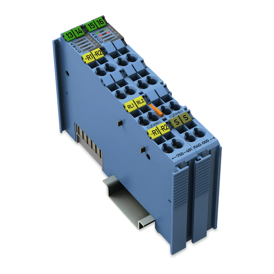
Device Description WAGO I/O SYSTEM 750 XTR 750-481/040-000 2AI RTD Ex i XTR View Figure 1: View Table 3: Legend for Figure “View” Pos. Description Details See Section Marking possibility with Mini- Status LEDs “Device Description” > “Display Elements” Data contacts “Device Description”... -
Page 17: Connectors
WAGO I/O SYSTEM 750 XTR Device Description 750-481/040-000 2AI RTD Ex i XTR Connectors 3.2.1 Data Contacts/Local Bus Communication between the fieldbus coupler/controller and the I/O modules as well as the system supply of the I/O modules is carried out via the local bus. The contacting for the local bus consists of 6 data contacts, which are available as self-cleaning gold spring contacts. -
Page 18: Power Jumper Contacts/Field Supply
The blade contacts are sharp-edged. Handle the I/O module carefully to prevent injury. Do not touch the blade contacts. The I/O module 750-481/040-000 has 2 self-cleaning power jumper contacts that supply and transmit power for the field side. The contacts on the left side of the I/O module are designed as blade contacts and those on the right side as spring contacts. -
Page 19: Cage Clamp ® Connectors
WAGO I/O SYSTEM 750 XTR Device Description 750-481/040-000 2AI RTD Ex i XTR 3.2.3 CAGE CLAMP ® Connectors Figure 4: CAGE CLAMP ® Connectors Table 5: Legend for Figure “CAGE CLAMP ® Connectors” Channel Designation Connector Function 1 (left) Input AI 1: Sensor +R... -
Page 20: Display Elements
Status AI 2 Operational readiness and trouble-free Green local bus communication Normal operation Overrange/underflow of the admissible Error AI 2 measuring range, broken wire, short circuit Operating Elements The I/O module 750-481/040-000 has no operating elements. Manual Version 1.1.0... -
Page 21: Schematic Diagram
WAGO I/O SYSTEM 750 XTR Device Description 750-481/040-000 2AI RTD Ex i XTR Schematic Diagram Figure 6: Schematic Diagram Manual Version 1.1.0... -
Page 22: Technical Data
Device Description WAGO I/O SYSTEM 750 XTR 750-481/040-000 2AI RTD Ex i XTR Technical Data 3.6.1 Device Data Table 7: Technical Data – Device Width 24 mm Height (from upper edge of DIN-rail) 60.6 mm Depth 100 mm Weight 91.6 g... -
Page 23: Explosion Protection
WAGO I/O SYSTEM 750 XTR Device Description 750-481/040-000 2AI RTD Ex i XTR 3.6.4 Explosion Protection Table 10: Technical Data – Explosion Protection Power supply = 26.8 V via power jumper contacts = 0.45 W power consumption Interface circuit (system bus) -
Page 24: Connection Type
Device Description WAGO I/O SYSTEM 750 XTR 750-481/040-000 2AI RTD Ex i XTR 3.6.6 Connection Type Table 12: Technical Data – Field Wiring Wire connection CAGE CLAMP ® Cross section 0.25 mm² … 2.5 mm² / AWG 24 … 14 Stripped lengths 8 mm …... -
Page 25: Approvals
WAGO I/O SYSTEM 750 XTR Device Description 750-481/040-000 2AI RTD Ex i XTR Approvals The following approvals have been granted for the I/O module 750-481/040-000: Conformity marking UL61010-2-201 Korea Certification The following Ex approvals have been granted for the I/O module 750-481/040- 000: TÜV 17 ATEX 196484 X... - Page 26 Device Description WAGO I/O SYSTEM 750 XTR 750-481/040-000 2AI RTD Ex i XTR The following shipbuilding approvals are pending for the I/O module 750- 481/040-000: ABS (American Bureau of Shipping) Temperature: D (cold testing at −40 °C/16 h) Relative humidity:...
-
Page 27: Standards And Guidelines
WAGO I/O SYSTEM 750 XTR Device Description 750-481/040-000 2AI RTD Ex i XTR Standards and Guidelines 750-481/040-000 I/O modules meet the following standards and guidelines: Table 17: Standards and Rated Conditions for Explosion Protection Applications ATEX acc. Directive 2014/34/EU General Requirements... -
Page 28: Table 18: Climatic And Mechanical Environmental Conditions And
Device Description WAGO I/O SYSTEM 750 XTR 750-481/040-000 2AI RTD Ex i XTR Table 18: Climatic and Mechanical Environmental Conditions and Shipbuilding Standard Test Value Transport EN 60870-2-2 Ct2(2k4) (except precipitation/water/moisture) Mechanical Environmental Conditions EN 61850-3 Achieved EN 60870-2-2 EN 60721-3-1... -
Page 29: Table 19: Emc - Immunity To Interference
WAGO I/O SYSTEM 750 XTR Device Description 750-481/040-000 2AI RTD Ex i XTR The I/O module 750-481/040-000 meets the following EMC standards as these standards relate to the I/O module: Table 19: EMC – Immunity to Interference Standard Test Value Electrostatic Discharge •... - Page 30 Device Description WAGO I/O SYSTEM 750 XTR 750-481/040-000 2AI RTD Ex i XTR Table 19: EMC – Immunity to Interference Standard Test Value Damped Oscillatory Waves • EN 61000-4-18 1.25 kV conductor/conductor • EN 60255-26 2.5 kV conductor/ground • IEEE C37.90.1...
-
Page 31: Table 20: Emc - Emission Of Interference
WAGO I/O SYSTEM 750 XTR Device Description 750-481/040-000 2AI RTD Ex i XTR Table 20: EMC – Emission of Interference Standard Test Value Enclosure Emission of Interference • EN 61000-6-3 30 dB(µV/m), QP, 30 MHz … 230 MHz • EN 55032 Class B 37 dB(µV/m), QP, 230 MHz …... - Page 32 Device Description WAGO I/O SYSTEM 750 XTR 750-481/040-000 2AI RTD Ex i XTR Table 20: EMC – Emission of Interference Standard Test Value Conducted Emission of Interference – Line Connection DC Voltage • EN 61000-6-3 79 dB(µV) QP, 0.15 MHz … 0.5 MHz •...
-
Page 33: Process Image
Evaluation of Status Byte Some fieldbus systems can process status information of process value by means of a status byte. This status byte can be displayed via the commissioning tool WAGO-I/O- CHECK. However, processing via the fieldbus coupler/controller is optional, which means that accessing or parsing the status information depends on the fieldbus system. -
Page 34: Table 21: Process Image At Configuration Pt100, Pt200, Pt500 And Pt1000
Process Image WAGO I/O SYSTEM 750 XTR 750-481/040-000 2AI RTD Ex i XTR Table 21: Process Image at Configuration Pt100, Pt200, Pt500 and Pt1000 Status Numerical value Temperature byte Error °C hex. AI 1, AI 2 binary hex. dec. < −200.0 '1000.0000.0000.0001' 0x8001... -
Page 35: Configuration For Ni Resistance Sensors
WAGO I/O SYSTEM 750 XTR Process Image 750-481/040-000 2AI RTD Ex i XTR Configuration for Ni Resistance Sensors To evaluate the nickel resistance sensors, the measured values of the resistance are converted and sent as temperature values. All temperature values are represented in a standard numeric format. -
Page 36: Table 23: Process Image At Configuration For Ni120
Process Image WAGO I/O SYSTEM 750 XTR 750-481/040-000 2AI RTD Ex i XTR Table 23: Process Image at Configuration for Ni120 Status Numerical value Temperature byte Error °C hex. AI 1, AI 2 binary hex. dec. < −80.0 '1000.0000.0000.0001' 0x8001 −32767... -
Page 37: Configuration For Resistance Measuring
WAGO I/O SYSTEM 750 XTR Process Image 750-481/040-000 2AI RTD Ex i XTR Configuration for Resistance Measuring Resistance measuring is only possible using 2-wire devices. The measured values are sent out directly when measuring the resistance. In the measuring range from 10 Ω to 1.2 kΩ, the resolution is 1 digit per 0.1 Ω. -
Page 38: Configuration For Potentiometer Measuring
Process Image WAGO I/O SYSTEM 750 XTR 750-481/040-000 2AI RTD Ex i XTR Configuration for Potentiometer Measuring Potentiometer measuring is only possible using 3-wire devices. When a potentiometer is used for measurement, the relative position of the connected potentiometer is expressed in percent:... -
Page 39: Mounting
750-481/040-000 2AI RTD Ex i XTR Mounting Mounting Sequence Fieldbus couplers, controllers and I/O modules of the WAGO I/O SYSTEM 750 are snapped directly on a carrier rail in accordance with the European standard EN 60175 (DIN 35). The reliable positioning and connection is made using a tongue and groove system. - Page 40 Always plug a bus end module 750-600/040-000 onto the end of the fieldbus node! You must always use this bus end module at all fieldbus nodes with the WAGO I/O SYSTEM 750 XTR fieldbus couplers/controllers to guarantee proper data transfer.
-
Page 41: Inserting And Removing Devices
WAGO I/O SYSTEM 750 XTR Mounting 750-481/040-000 2AI RTD Ex i XTR Inserting and Removing Devices Do not touch hot surfaces! The surface of the housing can become hot during operation. If the device was operated at high ambient temperatures, allow it to cool off before touching it. -
Page 42: Removing The I/O Module
Mounting WAGO I/O SYSTEM 750 XTR 750-481/040-000 2AI RTD Ex i XTR Press the I/O module into the assembly until the I/O module snaps into the carrier rail. Figure 8: Snap the I/O Module into Place (Example) With the I/O module snapped in place, the electrical connections for the data contacts and power jumper contacts (if any) to the fieldbus coupler/controller or to the previous or possibly subsequent I/O module are established. -
Page 43: Connect Devices
Do not connect more than one conductor at one single connection! If more than one conductor must be routed to one connection, these must be connected in an up-circuit wiring assembly, for example using WAGO feed- through terminals. For opening the CAGE CLAMP insert the actuating tool into the opening ®... -
Page 44: Power Supply Concept
Further information about explosion prevention can be found in section “Use in Hazardous Environments”! The Ex i XTR I/O module (750-481/040-000) receives the 24 V voltage supply potential and the 0V potential for the field level from an upstream Ex i XTR I/O module or from the “Power Supply 24 VDC Diagn for Ex i XTR Modules”... -
Page 45: Figure 11: Ex I Xtr Power Supply Concept
750-481/040-000 2AI RTD Ex i XTR 606/040-000 via the power contacts designed as blade contacts. The Ex i XTR I/O module (750-481/040-000) provides these potentials to subsequent I/O modules via the power contacts designed as spring contacts. Figure 11: Ex i XTR Power Supply Concept Table 27: Legend for Figure “Ex i XTR Power Supply Concept”... -
Page 46: Figure 12: Overvoltage Categories
Connect Devices WAGO I/O SYSTEM 750 XTR 750-481/040-000 2AI RTD Ex i XTR Figure 12: Overvoltage Categories Table 28: Legend for Figure “Overvoltage Categories” Pos. Explanation XTR fieldbus coupler/controller XTR filter module XTR supply module “Power Supply 24 VDC Diagn for Ex i XTR Modules”... -
Page 47: Supplementary Power Supply Regulations
6.2.1 Supplementary Power Supply Regulations The WAGO I/O SYSTEM 750 XTR can also be used in shipbuilding applications and onshore/offshore installations (e.g., platforms, loading facilities), as well as in telecontrol applications. This is possible via certification under the standards of leading agencies such as DNV GL and Lloyds Register. -
Page 48: Figure 13: Power Supply Concept, Example 1
Connect Devices WAGO I/O SYSTEM 750 XTR 750-481/040-000 2AI RTD Ex i XTR Figure 13: Power Supply Concept, Example 1 Table 30: Legend for Figure “Power Supply Concept, Example 1” Pos. Explanation XTR fieldbus coupler / controller XTR filter module 750-626/040-000 XTR supply “Power Supply 24 VDC Diagn for Ex i XTR Modules”... -
Page 49: Figure 14: Power Supply Concept, Example 2
WAGO I/O SYSTEM 750 XTR Connect Devices 750-481/040-000 2AI RTD Ex i XTR Figure 14: Power Supply Concept, Example 2 Table 31: Legend for Figure “Power Supply Concept, Example 2“ Pos. Explanation XTR fieldbus coupler / controller XTR filter module 750-626/040-000 XTR filter module (750-626/040-000 or 750-624/040-001) XTR supply 750-606/040-000 “Power Supply 24 VDC Diagn for Ex i XTR... -
Page 50: Connection Examples
Connect Devices WAGO I/O SYSTEM 750 XTR 750-481/040-000 2AI RTD Ex i XTR Connection Examples 6.3.1 2 × RTD, 2-Conductors Figure 15: Example Connection 2 × RTD, 2-Wire 6.3.2 2 × RTD, 3-Conductors Figure 16: Example Connection 2 × RTD, 3-Wire Manual Version 1.1.0... -
Page 51: Resistance
WAGO I/O SYSTEM 750 XTR Connect Devices 750-481/040-000 2AI RTD Ex i XTR 6.3.3 2 × Resistance Figure 17: Example Connection 2 × Resistance 6.3.4 2 × Potentiometer Figure 18: Example Connection 2 × Potentiometer Manual Version 1.1.0... -
Page 52: Use In Hazardous Environments
WAGO I/O SYSTEM 750 XTR 750-481/040-000 2AI RTD Ex i XTR Use in Hazardous Environments The WAGO I/O SYSTEM 750 (electrical equipment) is designed for use in Zone 2 hazardous areas and shall be used in accordance with the marking and installation regulations. -
Page 53: Marking Configuration Examples
WAGO I/O SYSTEM 750 XTR Use in Hazardous Environments 750-481/040-000 2AI RTD Ex i XTR Marking Configuration Examples 7.1.1 Marking for Europe According to ATEX and IECEx Figure 19: Marking Example According to ATEX and IECEx Figure 20: Text Detail – Marking Example According to ATEX and IECEx Manual Version 1.1.0... -
Page 54: Table 32: Description Of Marking Example According To Atex And Iecex
Use in Hazardous Environments WAGO I/O SYSTEM 750 XTR 750-481/040-000 2AI RTD Ex i XTR Table 32: Description of Marking Example According to ATEX and IECEx Marking Description TUEV 07 ATEX 554086 X Approving authority resp. certificate numbers IECEx TUN 09.0001 X... -
Page 55: Figure 21: Marking Example For Approved Ex I I/O Module According To Atex
WAGO I/O SYSTEM 750 XTR Use in Hazardous Environments 750-481/040-000 2AI RTD Ex i XTR Figure 21: Marking Example for Approved Ex i I/O Module According to ATEX and IECEx Figure 22: Text Detail – Marking Example for Approved Ex i I/O Module According to ATEX and... -
Page 56: Table 33: Description Of Marking Example For Approved Ex I I/O Module According To Atex And Iecex
Use in Hazardous Environments WAGO I/O SYSTEM 750 XTR 750-481/040-000 2AI RTD Ex i XTR Table 33: Description of Marking Example for Approved Ex i I/O Module According to ATEX and IECEx Marking Description TUEV 12 ATEX 106032 X Approving authority resp. certificate numbers... -
Page 57: Marking For The United States Of America (Nec) And Canada (Cec)
WAGO I/O SYSTEM 750 XTR Use in Hazardous Environments 750-481/040-000 2AI RTD Ex i XTR 7.1.2 Marking for the United States of America (NEC) and Canada (CEC) Figure 23: Marking Example According to NEC Figure 24: Text Detail – Marking Example According to NEC 500... -
Page 58: Figure 25: Text Detail - Marking Example For Approved Ex I I/O Module
Use in Hazardous Environments WAGO I/O SYSTEM 750 XTR 750-481/040-000 2AI RTD Ex i XTR Figure 25: Text Detail – Marking Example for Approved Ex i I/O Module According to NEC 505 Table 35: Description of Marking Example for Approved Ex i I/O Module According to NEC 505... -
Page 59: Figure 27: Text Detail - Marking Example For Approved Ex I I/O Modules
WAGO I/O SYSTEM 750 XTR Use in Hazardous Environments 750-481/040-000 2AI RTD Ex i XTR Figure 27: Text Detail – Marking Example for Approved Ex i I/O Modules According to CEC 18 attachment J Table 37: Description of Marking Example for Approved Ex i I/O Modules According to CEC 18... -
Page 60: Installation Regulations
Use in Hazardous Environments WAGO I/O SYSTEM 750 XTR 750-481/040-000 2AI RTD Ex i XTR Installation Regulations For the installation and operation of electrical equipment in hazardous areas, the valid national and international rules and regulations which are applicable at the installation location must be carefully followed. - Page 61 WAGO I/O SYSTEM 750 XTR Use in Hazardous Environments 750-481/040-000 2AI RTD Ex i XTR Explosive atmosphere occurring simultaneously with assembly, installation or repair work must be ruled out. Among other things, these include the following activities • Insertion and removal of components •...
-
Page 62: Special Notes Regarding Ansi/Isa Ex
Use in Hazardous Environments WAGO I/O SYSTEM 750 XTR 750-481/040-000 2AI RTD Ex i XTR 7.2.2 Special Notes Regarding ANSI/ISA Ex For ANSI/ISA Ex acc. to UL File E198726, the following additional requirements apply: • Use in Class I, Division 2, Group A, B, C, D or non-hazardous areas only •... -
Page 63: Appendix
PROFINET IO 750-377(/025-000): > Firmware Version 01 Behavior after Overwriting with WAGO-I/O-CHECK! If WAGO-I/O-CHECK is used to overwrite a parameterization made with the GSD file, the I/O module operates with the WAGO-I/O-CHECK settings until the 750-333/040-000 Fieldbus Couplers are restarted. -
Page 64: Profinet Io Fieldbus Couplers 750-375(/025-000), 750-377(/025-000)
Appendix WAGO I/O SYSTEM 750 XTR 750-481/040-000 2AI RTD Ex i XTR 8.1.1.2 PROFINET IO Fieldbus Couplers 750-375(/025-000), 750-377(/025-000) When using the aforementioned PROFINET IO fieldbus couplers, the process image size is configured by selecting the corresponding GSD entry. Table 39: PROFINET IO Configuration... -
Page 65: Figure 29: Example Of A Parameter Assignment Dialog For Profinet Io
WAGO I/O SYSTEM 750 XTR Appendix 750-481/040-000 2AI RTD Ex i XTR Figure 29: Example of a Parameter Assignment Dialog for PROFINET IO Fieldbus Couplers Manual Version 1.1.0... -
Page 66: All Profibus Dp And Profinet Io Fieldbus Couplers/Controllers
Appendix WAGO I/O SYSTEM 750 XTR 750-481/040-000 2AI RTD Ex i XTR 8.1.2.1 All PROFIBUS DP and PROFINET IO Fieldbus Couplers/Controllers The following assignment applies to the parameters of the I/O module when using PROFIBUS DP and PROFINET IO fieldbus devices. -
Page 67: Profibus Dp Fieldbus Couplers/Controllers
WAGO I/O SYSTEM 750 XTR Appendix 750-481/040-000 2AI RTD Ex i XTR 8.1.2.2 PROFIBUS DP Fieldbus Couplers/Controllers 750-333(/0xx-000), 750-833(/0xx-000) The aforementioned fieldbus couplers/controllers allow channel- and module- specific behavior parameterization during diagnostics. Table 41: General Module/Channel Parameters Parameter Value Explanation... -
Page 68: Profinet Io Fieldbus Couplers 750-375(/025-000), 750-377(/025-000)
Appendix WAGO I/O SYSTEM 750 XTR 750-481/040-000 2AI RTD Ex i XTR 8.1.2.3 PROFINET IO Fieldbus Couplers 750-375(/025-000), 750-377(/025-000) The aforementioned fieldbus couplers allow channel-specific behavior parameterization during diagnostics. Table 42: General Module/Channel Parameters Parameter Value Explanation Channel diagnostics 0 (false) An error on the respective signal channel does Channel x (x = 0 …... -
Page 69: List Of Figures
WAGO I/O SYSTEM 750 XTR List of Figures 750-481/040-000 2AI RTD Ex i XTR List of Figures Figure 1: View ...................... 16 Figure 2: Data Contacts ..................17 Figure 3: Power Jumper Contacts ............... 18 Figure 4: CAGE CLAMP Connectors ..............19 ®... -
Page 70: List Of Tables
List of Tables WAGO I/O SYSTEM 750 XTR 750-481/040-000 2AI RTD Ex i XTR List of Tables Table 1: Number Notation ..................7 Table 2: Font Conventions ..................7 Table 3: Legend for Figure “View” ............... 16 Table 4: Legend for Figure “Power Jumper Contacts” ......... 18 Table 5: Legend for Figure “CAGE CLAMP... - Page 71 WAGO I/O SYSTEM 750 XTR List of Tables 750-481/040-000 2AI RTD Ex i XTR Table 41: General Module/Channel Parameters ..........67 Table 42: General Module/Channel Parameters ..........68 Manual Version 1.1.0...
- Page 72 WAGO Kontakttechnik GmbH & Co. KG Postfach 2880 • D - 32385 Minden Hansastraße 27 • D - 32423 Minden Phone: +49 571 887 – 0 Fax: +49 571 887 – 844169 E-Mail: info@wago.com Internet: www.wago.com...
Need help?
Do you have a question about the 750-481/040-000 and is the answer not in the manual?
Questions and answers