Sign In
Upload
Manuals
Brands
WAGO Manuals
Control Unit
750-489
WAGO 750-489 Manuals
Manuals and User Guides for WAGO 750-489. We have
1
WAGO 750-489 manual available for free PDF download: Manual
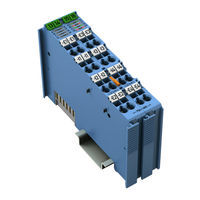
WAGO 750-489 Manual (178 pages)
4AI RTD/TC/Strain Gauge Ex i, 4-Channel Analog Input, RTD/TC/Strain Gauge, Intrinsically Safe for WAGO-I/O-SYSTEM 750 Series
Brand:
WAGO
| Category:
Control Unit
| Size: 6.61 MB
Table of Contents
Table of Contents
3
1 Notes about this Documentation
8
Validity of this Documentation
8
Revision History
8
Table 1: Revision History
8
Copyright
9
Symbols
10
Number Notation
12
Font Conventions
12
Table 2: Number Notation
12
Table 3: Font Conventions
12
2 Important Notes
13
Legal Bases
13
Subject to Changes
13
Personnel Qualifications
13
Use of the 750 Series in Compliance with Underlying Provisions
13
Technical Condition of Specified Devices
14
Disposal
14
2.1.4.1.1 Electrical and Electronic Equipment
14
2.1.4.1.2 Packaging
15
Safety Advice (Precautions)
16
3 Device Description
19
Table 4: Input Types
19
Table 5: Compatibility List 750-489
20
View
22
Figure 1: View
22
Table 6: Legend for Figure "View
22
Connectors
23
Data Contacts/Local Bus
23
Figure 2: Data Contacts
23
Power Jumper Contacts/Field Supply
24
Figure 3: Power Jumper Contacts
24
Table 7: Legend for Figure "Power Jumper Contacts
24
CAGE CLAMP ® Connectors
25
Figure 4: CAGE CLAMP ® Connectors
25
Table 8: Legend for Figure "CAGE CLAMP ® Connectors
25
Display Elements
26
Operating Elements
26
Figure 5: Display Elements
26
Table 9: Legend for Figure "Display Elements
26
Schematic Diagram
27
Figure 6: Schematic Diagram
27
Figure 7: Galvanic Isolation
27
Technical Data
28
Device Data
28
Power Supply
28
Communication
28
Table 10: Technical Data - Device
28
Table 11: Technical Data - Power Supply
28
Table 12: Technical Data - Communication
28
Inputs
29
Table 13: Technical Data - Inputs
29
Table 14: Technical Data - Sensor Types/Measurement Ranges
30
Explosion Protection
32
Table 15: Technical Data - Explosion Protection
32
Climatic Environmental Conditions
33
Connection Type
33
Table 16: Technical Data - Climatic Environmental Conditions
33
Table 17: Technical Data - Field Wiring
33
Table 18: Technical Data - Power Jumper Contacts
33
Table 19: Technical Data - Data Contacts
33
Approvals
34
Standards and Guidelines
36
4 Process Image
37
Overview
37
Status Bytes
38
Table 20: Process Image - 750-489 I/O Module
38
Table 21: Status Byte CH1_S0
38
Process Data
40
Overview of Sensor Types
40
Table 22: Process Data, Overview of Standard Format and S5-FB250 Format
40
Conversion of the Process Values
43
Temperature Measurements
43
Figure 8: Process of Calculating Measured Value from Process Value
43
Resistance and Voltage Measurements
44
Figure 9: Process of Calculating Measured Value from Process Value
44
Potentiometers
45
Figure 10: Process of Calculating Measured Value from Process Value
45
Temperature Measurement (Celsius)
46
Pt100, Pt200, Pt500, Pt1000 (en 60751)
47
S5-FB250 Format/Celsius
47
Standard Format/Celsius
47
Table 23: Pt100, Pt200, Pt500, Pt1000 (en 60751) Setting, Standard Format/Celsius
47
Table 24: Pt100, Pt200, Pt500, Pt1000 (en 60751) Setting, S5-FB250 Format/Celsius
47
Ni100, Ni120, Ni200, Ni500, Ni1000 (TK6180, DIN 43760), Ni1000 (TK5000, DIN 43760)
48
Table 25: Ni100, Ni120, Ni200, Ni500, Ni1000 Setting - Standard Format/Celsius
48
Table 26: Ni100, Ni120, Ni200, Ni500, Ni1000 Setting - S5-FB250 Format/Celsius
48
Table 27: TC Type B Setting - Standard Format/Celsius
49
Table 28: TC Type B Setting - S5-FB250 Format/Celsius
49
TC Type B - S5-FB250 Format/Celsius
49
TC Type B - Standard Format/Celsius
49
Thermocouples (DIN en 60584-1)
49
Table 29: TC Type C Setting - Standard Format/Celsius
50
Table 30: TC Type C Setting - S5-FB250 Format/Celsius
50
TC Type C - S5-FB250 Format/Celsius
50
TC Type C - Standard Format/Celsius
50
Table 31: TC Type E Setting - Standard Format/Celsius
51
Table 32: TC Type E Setting - S5-FB250 Format/Celsius
51
TC Type E - S5-FB250 Format/Celsius
51
TC Type E - Standard Format/Celsius
51
Table 33: TC Type J Setting - Standard Format/Celsius
52
Table 34: TC Type J Setting - S5-FB250 Format/Celsius
52
TC Type J - S5-FB250 Format/Celsius
52
TC Type J - Standard Format/Celsius
52
TC Type K - Standard Format/Celsius
53
TC Type K - S5-FB250 Format/Celsius
53
Table 35: TC Type K Setting - Standard Format/Celsius
53
Table 36: TC Type K Setting - S5-FB250 Format/Celsius
53
TC Type N - Standard Format/Celsius
54
TC Type N - S5-FB250 Format/Celsius
54
Table 37: TC Type N Setting - Standard Format/Celsius
54
Table 38: TC Type N Setting - S5-FB250 Format/Celsius
54
TC Type R and Type S - Standard Format/Celsius
55
TC Type R and Type S - S5-FB250 Format/Celsius
55
Table 39: TC Type R and Type S Setting - Standard Format/Celsius
55
Table 40: TC Type R and Type S Setting - S5-FB250 Format/Celsius
55
TC Type T - Standard Format/Celsius
56
TC Type T - S5-FB250 Format/Celsius
56
Table 41: TC Type T - Standard Format/Celsius
56
Table 42: TC Type T Setting - S5-FB250 Format/Celsius
56
Table 43: Temperature Measurement Setting with High Resolution Option - Standard Format/Celsius
57
Table 44: Type C TC Setting with High Resolution Option - Standard Format/Celsius
57
Temperature Measurements (RTD & TC) with High Resolution
57
Table 45: Temperature Measurement Setting with High Resolution Option - S5-FB250 Format/ Celsius
58
Table 46: Type C TC Setting with High Resolution Option - S5-FB250 Format/Celsius
58
Temperature Measurement (Fahrenheit)
59
Pt100, Pt200, Pt500, Pt1000 (en 60751)
60
S5-FB250 Format/ Fahrenheit
60
Standard Format/Fahrenheit
60
Table 47: Pt100, Pt200, Pt500, Pt1000 (en 60751) Setting, Standard
60
Table 48: Pt100, Pt200, Pt500, Pt1000 (en 60751) Setting
60
Ni100, Ni120, Ni200, Ni500, Ni1000 (TK6180, DIN 43760), Ni1000 (TK5000, DIN 43760)
61
S5-FB250 Format/Fahrenheit
61
Standard Format/Fahrenheit
61
Table 49: Ni100, Ni120, Ni200, Ni500, Ni1000 Setting - Standard
61
Table 50: Ni100, Ni120, Ni200, Ni500, Ni1000 Setting
61
Table 51: TC Type B Setting - Standard Format/Fahrenheit
62
Table 52: TC Type B Setting - S5-FB250 Format/Fahrenheit
62
TC Type B - S5-FB250 Format/Fahrenheit
62
TC Type B - Standard Format/Fahrenheit
62
Thermocouples (DIN en 60584-1)
62
Table 53: TC Type C Setting - Standard Format/Fahrenheit
63
Table 54: TC Type C Setting - S5-FB250 Format/Fahrenheit
63
TC Type C - S5-FB250 Format/Fahrenheit
63
TC Type C - Standard Format/Fahrenheit
63
Table 55: TC Type E Setting - Standard Format/Fahrenheit
64
Table 56: TC Type E Setting - S5-FB250 Format/Fahrenheit
64
TC Type E - S5-FB250 Format/Fahrenheit
64
TC Type E - Standard Format/Fahrenheit
64
Table 57: TC Type J Setting - Standard Format/Fahrenheit
65
Table 58: TC Type J Setting - S5-FB250 Format/Fahrenheit
65
TC Type J - S5-FB250 Format/Fahrenheit
65
TC Type J - Standard Format/Fahrenheit
65
TC Type K - Standard Format/Fahrenheit
66
TC Type K - S5-FB250 Format/Fahrenheit
66
Table 59: TC Type K Setting - Standard Format/Fahrenheit
66
Table 60: TC Type K Setting - S5-FB250 Format/Fahrenheit
66
TC Type N - Standard Format/Fahrenheit
67
TC Type N - S5-FB250 Format/Fahrenheit
67
Table 61: TC Type N Setting - Standard Format/Fahrenheit
67
Table 62: TC Type N Setting - S5-FB250 Format/Fahrenheit
67
TC Type R and Type S - Standard Format/Fahrenheit
68
TC Type R and Type S - S5-FB250 Format/Fahrenheit
68
Table 63: TC Type R and Type S Setting - Standard Format/Fahrenheit
68
Table 64: TC Type R and Type S Setting - S5-FB250 Format/Fahrenheit
68
TC Type T - Standard Format/Fahrenheit
69
TC Type T - S5-FB250 Format/Fahrenheit
69
Table 65: TC Type T Setting - Standard Format/Fahrenheit
69
Table 66: TC Type T Setting - S5-FB250 Format/Fahrenheit
69
Table 67: Temperature Measurement Setting with High Resolution Option - Standard Format/ Fahrenheit
70
Table 68: Type C TC Setting with High Resolution Option - Standard Format/Fahrenheit
70
Temperature Measurements (RTD & TC) with High Resolution
70
Table 69: Temperature Measurement Setting with High Resolution Option - S5-FB250 Format/ Fahrenheit
71
Table 70: Type C TC Setting with High Resolution Option - S5-FB250 Format/Fahrenheit
71
Temperature Measurement (Kelvin)
72
Pt100, Pt200, Pt500, Pt1000 (en 60751)
73
Standard Format/Kelvin
73
S5-FB250 Format/Kelvin
73
Table 71: Pt100, Pt200, Pt500, Pt1000 (en 60751) Setting, Standard
73
Table 72: Pt100, Pt200, Pt500, Pt1000 (en 60751) Setting
73
Ni100, Ni120, Ni200, Ni500, Ni1000 (TK6180, DIN 43760), Ni1000 (TK5000, DIN 43760)
74
Standard Format/Kelvin
74
S5-FB250 Format/Kelvin
74
Table 73: Ni100, Ni120, Ni200, Ni500, Ni1000 Setting - Standard Format
74
Table 74: Ni100, Ni120, Ni200, Ni500, Ni1000 Setting - S5-FB250 Format
74
Thermocouples (DIN en 60584-1)
75
TC Type B - Standard Format/Kelvin
75
TC Type B - S5-FB250 Format/Kelvin
75
Table 75: TC Type B Setting - Standard Format/Kelvin
75
Table 76: TC Type B Setting - S5-FB250 Format/Kelvin
75
TC Type C - Standard Format/Kelvin
76
TC Type C - S5-FB250 Format/Kelvin
76
Table 77: TC Type C Setting - Standard Format/Kelvin
76
Table 78: TC Type C Setting - S5-FB250 Format/Kelvin
76
TC Type E - Standard Format/Kelvin
77
TC Type E - S5-FB250 Format/Kelvin
77
Table 79: TC Type E Setting - Standard Format/Kelvin
77
Table 80: TC Type E Setting - S5-FB250 Format/Kelvin
77
TC Type J - Standard Format/Kelvin
78
TC Type J - S5-FB250 Format/Kelvin
78
Table 81: TC Type J Setting - Standard Format/Kelvin
78
Table 82: TC Type J Setting - S5-FB250 Format/Kelvin
78
TC Type K - Standard Format/Kelvin
79
TC Type K - S5-FB250 Format/Kelvin
79
Table 83: TC Type K Setting - Standard Format/Kelvin
79
Table 84: TC Type K Setting - S5-FB250 Format/Kelvin
79
TC Type N - Standard Format/Kelvin
80
TC Type N - S5-FB250 Format/Kelvin
80
Table 85: TC Type N Setting - Standard Format/Kelvin
80
Table 86: TC Type N Setting - S5-FB250 Format/Kelvin
80
TC Type R and Type S - Standard Format/Kelvin
81
TC Type R and Type S - S5-FB250 Format/Kelvin
81
Table 87: TC Type R and Type S Setting - Standard Format/Kelvin
81
Table 88: TC Type R and Type S Setting - S5-FB250 Format/Kelvin
81
TC Type T - Standard Format/Kelvin
82
TC Type T - S5-FB250 Format/Kelvin
82
Table 89: TC Type T - Standard Format/Kelvin
82
Table 90: TC Type T Setting - S5-FB250 Format/Kelvin
82
Temperature Measurements (RTD & TC) with High Resolution
83
Standard Format/Kelvin
83
Table 91: Temperature Measurement Setting with High Resolution Option
83
Table 92: Type C TC Setting with High Resolution Option - Standard
83
S5-FB250 Format/Kelvin
84
Table 93: Temperature Measurement Setting with High Resolution Option
84
Table 94: Type C TC Setting with High Resolution Option
84
Resistance Measurement
85
Resistance Measurement 1 (0 Ω
86
Table 95: Setting: Resistance Measurement 1 - Standard Format
86
Table 96: Setting: Resistance Measurement 1 - S5-FB250 Format
86
Resistance Measurement 2 (0 Ω
87
Table 97: Setting: Resistance Measurement 2 - Standard Format
87
Table 98: Setting: Resistance Measurement 2 - S5-FB250 Format
87
Resistance Measurement 3 (0 Ω
88
Table 99: Setting: Resistance Measurement 3 - Standard Format
88
Table 100: Setting: Resistance Measurement 3 - S5-FB250 Format
88
Resistance Measurement 4 (0 Ω
89
Table 101: Setting: Resistance Measurement 4 - Standard Format
89
Table 102: Setting: Resistance Measurement 4 - S5-FB250 Format
89
Resistance Measurement 5 (0 Ω
90
Table 103: Setting: Resistance Measurement 5 - Standard Format
90
Table 104: Setting: Resistance Measurement 5 - S5-FB250 Format
90
Resistance Measurement PTC
91
Table 105: Setting: Resistance Measurement PTC - Standard Format
91
Table 106: Setting: Resistance Measurement PTC - S5-FB250 Format
91
Resistance Measurement (Potentiometer)
92
Table 107: Setting: Resistance Measurement (Potentiometer) - Standard
92
Table 108: Setting: Resistance Measurement (Potentiometer)
93
Voltage Measurement
94
Voltage Measurement 1 (±30 MV)
95
Table 109: Setting Voltage Measurement 1 (±30 MV) - Standard Format
95
Table 110: Setting Voltage Measurement 1 (±30 MV) - S5-FB250 Format
95
Voltage Measurement 2 (±60 MV)
96
Table 111: Setting Voltage Measurement 2 (±60 MV) - Standard Format
96
Table 112: Setting Voltage Measurement 2 (±60 MV) - S5-FB250 Format
96
Voltage Measurement 3 (±120 MV)
97
Table 113: Setting Voltage Measurement 3 (±120 MV) - Standard Format
97
Table 114: Setting Voltage Measurement 3 (±120 MV) - S5-FB250 Format
97
Voltage Measurement 4 (±250 MV)
98
Table 115: Setting Voltage Measurement 4 (±250 MV) - Standard Format
98
Table 116: Setting Voltage Measurement 4 (±250 MV) - S5-FB250 Format
98
Voltage Measurement 5 (±500 MV)
99
Table 117: Setting Voltage Measurement 5 (±500 MV) - Standard Format
99
Table 118: Setting Voltage Measurement 5 (±500 MV) - S5-FB250 Format
99
Voltage Measurement 6 (±1000 MV)
100
Table 119: Setting Voltage Measurement 6 (±1000 MV) - Standard Format
100
Table 120: Setting Voltage Measurement 6 (±1000 MV) - S5-FB250 Format
100
Voltage Measurement 7 (±2000 MV)
101
Table 121: Setting Voltage Measurement 7 (±2000 MV) - Standard Format
101
Table 122: Setting Voltage Measurement 7 (±2000 MV) - S5-FB250 Format
101
Resistor Bridge (Strain Gauge)
102
Strain Gauge Bridge Supply U (2.4 V)
103
Table 123 Setting Strain Gauge Bridge Supply U
103
Table 124: Setting Strain Gauge Bridge Supply U
103
Strain Gauge Bridge Voltage U (±15 MV)
104
Table 125: Setting Strain Gauge Bridge Voltage U
104
Table 126: Setting Strain Gauge Bridge Voltage U
104
Strain Gauge Bridge Voltage U (±30 MV)
105
Table 127: Setting Strain Gauge Bridge Voltage U
105
Table 128: Setting Strain Gauge Bridge Voltage U
105
Strain Gauge Bridge Voltage U (±60 MV)
106
Table 129: Setting Strain Gauge Bridge Voltage U
106
Table 130: Setting Strain Gauge Bridge Voltage U
106
5 Mounting
107
Mounting Sequence
108
Inserting and Removing Devices
109
Inserting the I/O Module
109
Figure 11: Inserting I/O Module (Example)
109
Figure 12: Snap the I/O Module into Place (Example)
109
Removing the I/O Module
110
Figure 13: Removing the I/O Module (Example)
110
6 Connect Devices
111
Connecting a Conductor to the CAGE CLAMP
111
Figure 14: Connecting a Conductor to a CAGE CLAMP
111
Power Supply Concept
112
Figure 15: Supply Principle Ex I
113
Table 131: Legend for Figure "Ex I Power Supply Concept
113
Power Supply Concept for Marine Applications in Ex I
114
Figure 16: Overvoltage Categories
114
Table 132: Legend for Figure "Overvoltage Categories
114
Figure 17: Power Supply Concept for Marine Applications in Ex I - Class a (Shown with 750-624/XXX-XXX for Field 2)
115
Table 133: Legend for Figure "Power Supply Concept for Marine Applications in Ex I - Class a (Shown with 750-624/XXX-XXX for Field 2)
115
Table 134: Explanation of the Legend for Figure "Power Supply Concept for
115
Figure 18: Power Supply Concept for Marine Applications in Ex I - Class B (Shown with 750-626/XXX-XXX for Field 2)
116
Table 135: Legend for Figure "Power Supply Concept for Marine Applications in Ex I - Class B (Shown with 750-626/XXX-XXX for Field 2)
116
Table 136: Explanation of the Legend for Figure "Power Supply Concept for
116
Connection Examples
117
Rtds - Resistance Thermometers
117
Figure 19: Connection Example: RTD (Resistance Thermometer), 2- and
117
Figure 20: Connection Example: RTD (Resistance Thermometer), 4-Wire
117
Tcs - Thermocouples
118
Millivolt Transmitters
118
Figure 21: Connection Example: TC (Thermocouple)
118
Figure 22: Connection Example: Millivolt Transmitter
118
Potentiometer Setting
119
PTC Probes - Thermistors
119
Figure 23: Connection Example: Resistance Measurement (Potentiometer Setting)
119
Figure 24: Connection Example: PTC Probe (Thermistor)
119
Resistor Bridges (Strain Gauge)
120
Figure 25: Connection Example: Resistor Bridges (Strain Gauge)
120
Table 137: Terminal Assignment - Resistor Bridge (Strain Gauge)
120
7 Commissioning
121
Configuration and Parameterization with WAGO-I/O-CHECK
122
Table 138: Settings Using Tools
122
Figure 26: WAGO-I/O-CHECK User Interface (Example)
124
Parameterization Dialog
125
Title Bar
125
Figure 27: I/O Module Parameterization Dialog
125
Information Bar
126
Buttons
126
Table 139: Buttons
126
Menu
127
Settings Via the Menu
127
Common
127
Figure 28: "Common" Menu Item
127
Table 140: Navigation Via the Menu
127
Table 141: "Common" Menu Item
128
Channel Settings
129
Figure 29: Menu Item "Channel 1" (Example)
129
Table 142: Menu Items "Channel 1
130
Scaling
132
Figure 30: "Scaling" Menu Item (Example Channel 1)
133
Table 143: "Scaling" Menu Item, Channel 1
134
Calibration
135
Figure 31: "Calibration" Menu Item (Example Channel 1)
135
Table 144: "Calibration" Menu Item, Channel 1
136
Figure 32: "User Calibration" Dialog - Offset Correction
137
Figure 33: "User Calibration" Dialog - Gain Correction
137
Calculation
138
Figure 34: "Calculation" Menu Item
138
Figure 35: Context Menu
139
Configuration and Parameterization with E!Cockpit
140
Configuration and Parameterization Via GSD File
140
750-489 (4AI Rtd/Tc/Strain Gauge Ex I) Configuration
140
PROFIBUS DP Fieldbus Couplers/Controllers 750-333(/0Xx-000), 750-833(/0Xx-000)
140
Table 145: PROFIBUS DP Configuration
140
PROFINET IO Fieldbus Couplers 750-375(/025-000), 750-377(/025-000)
141
Table 146: PROFINET IO Configuration
141
4AI Rtd/Tc/Strain Gauge Ex I) Parameterization
142
PROFIBUS DP Fieldbus Couplers/Controllers 750-333(/0Xx-000), 750-833(/0Xx-000)
142
Figure 36: Example "Device-Specific Parameters" Dialog with PROFIBUS DP
142
PROFINET IO Fieldbus Couplers 750-375(/025-000), 750-377(/025-000)
143
Figure 37: Example "Specific Module/Channel Parameters" Dialog with
143
All PROFIBUS DP and PROFINET IO Fieldbus Couplers
144
Table 147: "Device-Specific Parameters" or "Specific Module/Channel
145
PROFIBUS DP Fieldbus Couplers 750-333(/0Xx-000), 750-833(/0Xx-000)
146
PROFINET IO Fieldbus Couplers 750-375(/025-000), 750-377(/025-000)
146
Table 148: General Module/Channel Parameters
146
Table 149: Specific Module/Channel Parameters
146
8 Scaling Measured Values
148
Table 150: Variable Legend - Scaling Measured Values
148
9 Calibrating Measured Values
149
Figure 38: Simplified Signal Sequence in the RTD/TC Module
150
Table 151: Temperatures for Adjustments
150
10 Diagnostics
151
Behavior of the I/O Module in the Event of Error
151
Table 152: Priority Levels of Diagnostic Functions
151
Table 153: Behavior of the I/O Module in the Event of Overflow/Underflow
152
Table 154: Behavior of the I/O Module in the Event of Range Violation
153
Diagnostics Via LED Indicators
154
Table 155: Signal Evaluation for each Channel - Status LED
154
Table 156: Signal Evaluation for each Channel - Error LED
154
11 Use in Hazardous Environments
155
Marking Configuration Examples
156
Marking for Europe According to ATEX and Iecex
156
Figure 39: Marking Example Per ATEX and Iecex
156
Figure 40: Text Detail - Marking Example Per ATEX and Iecex
156
Table 157: Description of the Marking Example Per ATEX and Iecex
157
Figure 41: Marking Example of an Approved I/O Module Ex I Per ATEX and
158
Figure 42: Text Detail - Marking Example of an Approved I/O Module Ex I
158
Table 158: Description of the Marking Example of an Approved I/O Module Ex I Per ATEX and Iecex
159
(Cec)
160
Figure 43: Marking Example According to NEC
160
Figure 44: Text Detail - Marking Example According to NEC 500
160
Table 159: Description of Marking Example According to NEC 500
160
Figure 45: Text Detail - Marking Example for Approved Ex I I/O Module
161
Figure 46: Text Detail - Marking Example for Approved Ex I I/O Module
161
Table 160: Description of Marking Example for Approved Ex I I/O Module
161
Table 161: Description of Marking Example for Approved Ex I I/O Modules
161
Figure 47: Text Detail - Marking Example for Approved Ex I I/O Modules
162
Table 162: Description of Marking Example for Approved Ex I I/O Modules
162
Installation Regulations
163
Special Notes Including Explosion Protection
163
Special Notes Regarding UL Hazardous Location
165
12 Service
166
Firmware Update/Downgrade
166
Recalibration
167
WAGO UII (Unique Item Identifier)
168
13 Appendix
169
Strain Gauge Application Example
169
List of Figures
170
List of Tables
172
Advertisement
Advertisement
Related Products
WAGO 750-481/040-000
WAGO 750-486/040-000
WAGO 750-486
WAGO 750-483/040-000
WAGO 750-482/000-001
WAGO 750-482
WAGO 750-468/040-000
WAGO 750-469/040-000
WAGO 750-458
WAGO 750-431/040-000
WAGO Categories
I/O Systems
Control Unit
Power Supply
Switch
Controller
More WAGO Manuals
Login
Sign In
OR
Sign in with Facebook
Sign in with Google
Upload manual
Upload from disk
Upload from URL