
Related Manuals for WAGO 750-486/040-000


Summary of Contents for WAGO 750-486/040-000
- Page 1 Manual WAGO-I/O-SYSTEM 750 XTR 750-486/040-000 4AI 0/4-20mA NE43 Ex i XTR 4-channel analog input; 0/4 … 20 mA; NE43; intrinsically safe; extreme Version 1.0.0...
- Page 2 We wish to point out that the software and hardware terms as well as the trademarks of companies used and/or mentioned in the present manual are generally protected by trademark or patent. WAGO is a registered trademark of WAGO Verwaltungsgesellschaft mbH. Manual Version 1.0.0...
-
Page 3: Table Of Contents
WAGO-I/O-SYSTEM 750 XTR Table of Contents 750-486/040-000 4AI 0/4-20mA NE43 Ex i XTR Table of Contents Notes about this Documentation ............. 6 Validity of this Documentation..............6 Copyright ....................6 Symbols ....................7 Number Notation ..................9 Font Conventions ................... 9 Important Notes .................. - Page 4 Table of Contents WAGO-I/O-SYSTEM 750 XTR 750-486/040-000 4AI 0/4-20mA NE43 Ex i XTR 4.3.3.1 Sensor Type “0-20 mA” ............... 42 4.3.3.2 Sensor Type “4-20 mA” ............... 43 4.3.3.3 Sensor Typ “3,6-21 mA” (NAMUR NE43) ........44 Mounting ....................45 Mounting Sequence ................45 Inserting and Removing Devices ............
- Page 5 WAGO-I/O-SYSTEM 750 XTR Table of Contents 750-486/040-000 4AI 0/4-20mA NE43 Ex i XTR Appendix ....................95 10.1 Configuration and Parameterization via GSD for PROFIBUS DP and PROFINET IO ..................95 10.1.1 Configuration 4AI 0/4-20 mA Ex i (NAMUR) ........95 10.1.1.1...
-
Page 6: Notes About This Documentation
(4AI 0/4-20mA NE43 Ex i XTR). The I/O module 750-486/040-000 shall only be installed and operated according to the instructions in this manual, in the system description for the WAGO-I/O- SYSTEM 750 XTR and in the manual for the used fieldbus coupler/controller. -
Page 7: Symbols
WAGO-I/O-SYSTEM 750 XTR Notes about this Documentation 750-486/040-000 4AI 0/4-20mA NE43 Ex i XTR Symbols Personal Injury! Indicates a high-risk, imminently hazardous situation which, if not avoided, will result in death or serious injury. Personal Injury Caused by Electric Current! Indicates a high-risk, imminently hazardous situation which, if not avoided, will result in death or serious injury. - Page 8 Notes about this Documentation WAGO-I/O-SYSTEM 750 XTR 750-486/040-000 4AI 0/4-20mA NE43 Ex i XTR Additional Information: Refers to additional information which is not an integral part of this documentation (e.g., the Internet). Manual Version 1.0.0...
-
Page 9: Number Notation
WAGO-I/O-SYSTEM 750 XTR Notes about this Documentation 750-486/040-000 4AI 0/4-20mA NE43 Ex i XTR Number Notation Table 1: Number Notation Number Code Example Note Decimal Normal notation Hexadecimal 0x64 C notation Binary '100' In quotation marks, nibble separated '0110.0100' with dots (.) -
Page 10: Important Notes
2.1.1 Subject to Changes WAGO Kontakttechnik GmbH & Co. KG reserves the right to provide for any alterations or modifications. WAGO Kontakttechnik GmbH & Co. KG owns all rights arising from the granting of patents or from the legal protection of utility patents. -
Page 11: Technical Condition Of Specified Devices
These modules contain no parts that can be serviced or repaired by the user. The following actions will result in the exclusion of liability on the part of WAGO Kontakttechnik GmbH & Co. KG: •... -
Page 12: Safety Advice (Precautions)
Install the device only in appropriate housings, cabinets or in electrical operation rooms! The WAGO-I/O-SYSTEM 750 and its components are an open system. As such, install the system and its components exclusively in appropriate housings, cabinets or in electrical operation rooms. Allow access to such equipment and fixtures to authorized, qualified staff only by means of specific keys or tools. - Page 13 WAGO-I/O-SYSTEM 750 XTR Important Notes 750-486/040-000 4AI 0/4-20mA NE43 Ex i XTR Protect the components against materials having seeping and insulating properties! The components are not resistant to materials having seeping and insulating properties such as: aerosols, silicones and triglycerides (found in some hand creams).
-
Page 14: Device Description
Power to the internal electronics is supplied via both the internal data bus and the field supply. The I/O module 750-486/040-000 (4AI 0/4-20mA NE43 Ex i XTR) receives the 24 V voltage supply for the field level from an upstream I/O module or from the fieldbus coupler/controller via blade-formed power jumper contacts. -
Page 15: Table 3: Compatibility List 750-486/040-000
An arrangement in groups within the group of potentials is not necessary. The 750-486/040-000 module can be used with the fieldbus couplers and controllers of the WAGO-I/O-SYSTEM 750 of the specified version or higher listed in the “Compatibility list”... - Page 16 Device Description WAGO-I/O-SYSTEM 750 XTR 750-486/040-000 4AI 0/4-20mA NE43 Ex i XTR Table 3: Compatibility List 750-486/040-000 Fieldbus couplers/ Revision status Bus system Item no. controllers – firmware 750-337 Fieldbus coupler 750-338 750-338/040-000 750-347 CANopen ECO fieldbus coupler 750-348 750-837...
-
Page 17: View
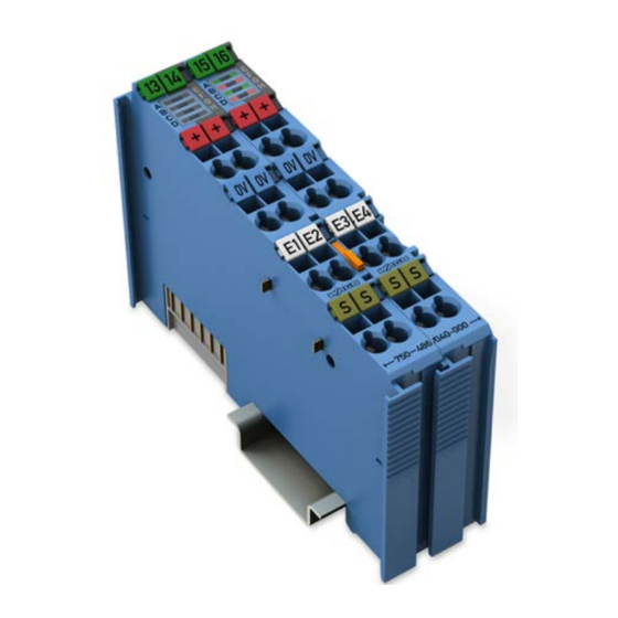
WAGO-I/O-SYSTEM 750 XTR Device Description 750-486/040-000 4AI 0/4-20mA NE43 Ex i XTR View Figure 1: View Table 4: Legend for Figure “View” Pos. Description Details See Section Marking possibility with Mini- Status LEDs “Device Description” > “Display Elements” Data contacts “Device Description”... -
Page 18: Connectors
Device Description WAGO-I/O-SYSTEM 750 XTR 750-486/040-000 4AI 0/4-20mA NE43 Ex i XTR Connectors 3.2.1 Data Contacts/Local Bus Communication between the fieldbus coupler/controller and the I/O modules as well as the system supply of the I/O modules is carried out via the local bus. It is comprised of 6 data contacts, which are available as self-cleaning gold spring contacts. -
Page 19: Power Jumper Contacts/Field Supply
The blade contacts are sharp-edged. Handle the I/O module carefully to prevent injury. The I/O module 750-486/040-000 has 2 self-cleaning power jumper contacts that supply and transmit power for the field side. The contacts on the left side of the I/O module are designed as blade contacts and those on the right side as spring contacts. -
Page 20: Cage Clamp Connectors
Device Description WAGO-I/O-SYSTEM 750 XTR 750-486/040-000 4AI 0/4-20mA NE43 Ex i XTR ® 3.2.3 CAGE CLAMP Connectors ® Figure 4: CAGE CLAMP Connectors ® Table 6: Legend for Figure “CAGE CLAMP Connectors“ Channel Designation Connector Function Input AI 1: Sensor supply U... -
Page 21: Display Elements
WAGO-I/O-SYSTEM 750 XTR Device Description 750-486/040-000 4AI 0/4-20mA NE43 Ex i XTR Display Elements Figure 5: Display Elements Table 7: Legend for Figure “Display Elements” Channel Designation LED State Function Not ready for operation or no or disturbed local bus communication, channel... -
Page 22: Operating Elements
Permissible measurement range Error AI 4 overrange/underrange, short circuit, general error, wire break (for sensor types “4 mA … 20 mA” and “3.6… 21 mA”) Operating Elements The I/O module 750-486/040-000 has no operating elements. Manual Version 1.0.0... -
Page 23: Schematic Diagram
WAGO-I/O-SYSTEM 750 XTR Device Description 750-486/040-000 4AI 0/4-20mA NE43 Ex i XTR Schematic Diagram Figure 6: Schematic Diagram Manual Version 1.0.0... -
Page 24: Technical Data
Device Description WAGO-I/O-SYSTEM 750 XTR 750-486/040-000 4AI 0/4-20mA NE43 Ex i XTR Technical Data 3.6.1 Device Table 8: Technical Data – Device Width 24 mm Height (from upper edge of DIN 35 rail) 60.6 mm Length 100 mm Weight 96.9 g... -
Page 25: Inputs
WAGO-I/O-SYSTEM 750 XTR Device Description 750-486/040-000 4AI 0/4-20mA NE43 Ex i XTR 3.6.3 Inputs Table 10: Technical Data – Inputs Number of inputs Signal type (switchable) 0 … +20 mA +4 … +20 mA +3.6 … +21 mA (NE43) Signal characteristic... -
Page 26: Explosion Protection
Device Description WAGO-I/O-SYSTEM 750 XTR 750-486/040-000 4AI 0/4-20mA NE43 Ex i XTR 3.6.4 Explosion Protection Table 11: Technical Data – Explosion Protection Power supply = 26.8 V via power jumper contacts = 2.7 W power consumption Interface circuit (system bus) -
Page 27: Connection Type
WAGO-I/O-SYSTEM 750 XTR Device Description 750-486/040-000 4AI 0/4-20mA NE43 Ex i XTR 3.6.6 Connection Type Table 13: Technical Data – Field Wiring ® Wire connection CAGE CLAMP Cross section 0.25 mm² … 2.5 mm² / AWG 24 … 14 Stripped lengths 8 mm …... -
Page 28: Approvals
Device Description WAGO-I/O-SYSTEM 750 XTR 750-486/040-000 4AI 0/4-20mA NE43 Ex i XTR Approvals The following approvals have been granted for the I/O module 750-486/040-000: Conformity marking The following approvals are pending for the I/O module 750-486/040-000: UL61010-2-201 Korea Certification The following Ex approvals have been granted for the I/O module 750-486/040- 000: TÜV 17 ATEX 196484 X... - Page 29 Env. 1, 2, 3, 4 More information about approvals. Detailed references to the approvals are listed in the document “Overview Approvals WAGO-I/O-SYSTEM 750”, which you can find via the internet under: www.wago.com > SERVICES > DOWNLOADS > Additional documentation and information on automation products >...
-
Page 30: Standards And Guidelines
Device Description WAGO-I/O-SYSTEM 750 XTR 750-486/040-000 4AI 0/4-20mA NE43 Ex i XTR Standards and Guidelines 750-486/040-000 I/O modules meet the following standards and guidelines: Table 18: Standards and Rated Conditions for Explosion Protection Applications ATEX acc. Directive 2014/34/EU General Requirements... - Page 31 WAGO-I/O-SYSTEM 750 XTR Device Description 750-486/040-000 4AI 0/4-20mA NE43 Ex i XTR Table 19: Climatic and Mechanical Environmental Conditions and Shipbuilding Standard Test Value Transport EN 60870-2-2 Ct2(2k4) (except precipitation/water/moisture) Mechanical Environmental Conditions EN 61850-3 Achieved EN 60870-2-2 EN 60721-3-1...
-
Page 32: Table 20: Emc - Immunity To Interference
Device Description WAGO-I/O-SYSTEM 750 XTR 750-486/040-000 4AI 0/4-20mA NE43 Ex i XTR The I/O module 750-486/040-000 meets the following EMC standards as these standards relate to the I/O module: Table 20: EMC – Immunity to Interference Standard Test Value Electrostatic Discharge •... - Page 33 WAGO-I/O-SYSTEM 750 XTR Device Description 750-486/040-000 4AI 0/4-20mA NE43 Ex i XTR Table 20: EMC – Immunity to Interference Standard Test Value Damped Oscillatory Waves • EN 61000-4-18 1.25 kV conductor/conductor • EN 60255-26 2.5 kV conductor/ground • IEEE C37.90.1...
-
Page 34: Table 21: Emc - Emission Of Interference
Device Description WAGO-I/O-SYSTEM 750 XTR 750-486/040-000 4AI 0/4-20mA NE43 Ex i XTR Table 21: EMC – Emission of Interference Standard Test Value Enclosure Emission of Interference • EN 61000-6-3 30 dB(µV/m), QP, 30 MHz … 230 MHz • EN 55022 Class B 37 dB(µV/m), QP, 230 MHz …... -
Page 35: Table 22: Standards And Rated Conditions For Rail Applications (En 50155)
1.3 × U 5.1.1.2 Power interruptions 5.4 Surge, ESD, Burst Tests EN 50121-3-2 5.5 EMC (Emission of Interference, EN 50121-3-2 Immunity to Interference) EN 50121-4 EN 50121-5 WAGO is a company certified in accordance with the IRIS quality standard. Manual Version 1.0.0... -
Page 36: Process Image
750-486/040-000 4AI 0/4-20mA NE43 Ex i XTR Process Image The 750-486/040-000 I/O module provides 1 status byte (8 bits) and 1 data word (16 bits) per channel. The I/O module supplies the input current range 0 mA … 20 mA or 4 mA …... -
Page 37: Overview
In the other process image, depending on the fieldbus coupler/controller, the representation of control/status bytes can be suppressed. Table 23: Process Image – I/O Module 750-486/040-000 Process image Input... -
Page 38: Status Bytes
Process Image WAGO-I/O-SYSTEM 750 XTR 750-486/040-000 4AI 0/4-20mA NE43 Ex i XTR Status Bytes Status bytes are identically implemented for all channels. Therefore, the following description in this section applies to all status bytes of the I/O module. Table 24: Status Byte CH1_S0... -
Page 39: Process Data
WAGO-I/O-SYSTEM 750 XTR Process Image 750-486/040-000 4AI 0/4-20mA NE43 Ex i XTR Process Data 4.3.1 Overview of Sensor Types The following table serves as an overview of all supported sensor types. The following sections contain detailed information about the individual sensor types. -
Page 40: Sensor Type "4-20 Ma
Process Image WAGO-I/O-SYSTEM 750 XTR 750-486/040-000 4AI 0/4-20mA NE43 Ex i XTR 4.3.2.2 Sensor Type “4-20 mA” For the current measurement with sensor type “4-20 mA”, the input range of 4 mA … +20 mA is mapped to a value rage of 0 … +32763. -
Page 41: Sensor Typ "3,6-21 Ma" (Namur Ne43)
WAGO-I/O-SYSTEM 750 XTR Process Image 750-486/040-000 4AI 0/4-20mA NE43 Ex i XTR 4.3.2.3 Sensor Typ “3,6-21 mA” (NAMUR NE43) For the current measurement with sensor type “3,6-21 mA” , the input range of +3,6 mA … +21 mA is mapped to a value rage of −765 … +32763. -
Page 42: Special Format (Amount/Sign Format)
Process Image WAGO-I/O-SYSTEM 750 XTR 750-486/040-000 4AI 0/4-20mA NE43 Ex i XTR 4.3.3 Special Format (Amount/Sign Format) 4.3.3.1 Sensor Type “0-20 mA” For the current measurement with sensor type “0-20 mA”, the input range of 0 mA … +20 mA is mapped to a process value rage of 0 … +32763. -
Page 43: Sensor Type "4-20 Ma
WAGO-I/O-SYSTEM 750 XTR Process Image 750-486/040-000 4AI 0/4-20mA NE43 Ex i XTR 4.3.3.2 Sensor Type “4-20 mA” For the current measurement with sensor type “4-20 mA”, the input range of 4 mA… +20 mA is mapped to a value rage of 0 … +32763. -
Page 44: Sensor Typ "3,6-21 Ma" (Namur Ne43)
Process Image WAGO-I/O-SYSTEM 750 XTR 750-486/040-000 4AI 0/4-20mA NE43 Ex i XTR 4.3.3.3 Sensor Typ “3,6-21 mA” (NAMUR NE43) For the current measurement with sensor type “3,6-21 mA” , the input range of +3,6 mA … +21 mA is mapped to a value rage of −771 … +32763. -
Page 45: Mounting
750-486/040-000 4AI 0/4-20mA NE43 Ex i XTR Mounting Mounting Sequence Fieldbus couplers/controllers and I/O modules of the WAGO-I/O-SYSTEM 750 are snapped directly on a carrier rail in accordance with the European standard EN 50022 (DIN 35). The reliable positioning and connection is made using a tongue and groove system. -
Page 46: Inserting And Removing Devices
Mounting WAGO-I/O-SYSTEM 750 XTR 750-486/040-000 4AI 0/4-20mA NE43 Ex i XTR Inserting and Removing Devices Do not touch hot surfaces! The surface of the housing can become hot during operation. If the device was operated at high ambient temperatures, allow it to cool off before touching it. -
Page 47: Removing The I/O Module
WAGO-I/O-SYSTEM 750 XTR Mounting 750-486/040-000 4AI 0/4-20mA NE43 Ex i XTR Figure 8: Snap the I/O Module into Place (Example) With the I/O module snapped in place, the electrical connections for the data contacts and power jumper contacts (if any) to the fieldbus coupler/controller or to the previous or possibly subsequent I/O module are established. -
Page 48: Connect Devices
Only one conductor may be connected to each CAGE CLAMP Do not connect more than one conductor at one single connection! If more than one conductor must be routed to one connection, these must be connected in an up-circuit wiring assembly, for example using WAGO feed- through terminals. ®... -
Page 49: Power Supply Concept
WAGO-I/O-SYSTEM 750 XTR Connect Devices 750-486/040-000 4AI 0/4-20mA NE43 Ex i XTR Power Supply Concept Ex i XTR I/O modules shall only be supplied via “Power Supply 24 VDC Diagn for Ex I XTR Modules” Ex i XTR I/O modules shall only be operated with a “Power Supply 24 VDC Diagn for Ex I XTR Modules”... -
Page 50: Figure 11: Ex I Xtr Power Supply Concept
Connect Devices WAGO-I/O-SYSTEM 750 XTR 750-486/040-000 4AI 0/4-20mA NE43 Ex i XTR Figure 11: Ex i XTR Power Supply Concept Table 31: Legend for Figure “Ex i XTR Power Supply Concept” Pos. Explanation XTR fieldbus coupler / controller XTR I/O modules XTR supply „Power Supply 24 VDC Diagn for Ex i XTR Modules“... -
Page 51: Figure 12: Overvoltage Categories
WAGO-I/O-SYSTEM 750 XTR Connect Devices 750-486/040-000 4AI 0/4-20mA NE43 Ex i XTR Figure 12: Overvoltage Categories Table 32: Legend for Figure “Overvoltage Categories” Pos. Explanation XTR fieldbus coupler/controller XTR filter module XTR supply module “Power Supply 24 VDC Diagn for Ex i XTR Modules”... -
Page 52: Supplementary Power Supply Regulations
Connect Devices WAGO-I/O-SYSTEM 750 XTR 750-486/040-000 4AI 0/4-20mA NE43 Ex i XTR 6.2.1 Supplementary Power Supply Regulations The I/O-SYSTEM 750 XTR can also be used in shipbuilding applications and onshore/offshore installations (e.g., platforms, loading facilities), as well as in the rail sector and telecontrol applications. -
Page 53: Figure 13: Power Supply Concept, Example 1
WAGO-I/O-SYSTEM 750 XTR Connect Devices 750-486/040-000 4AI 0/4-20mA NE43 Ex i XTR Figure 13: Power Supply Concept, Example 1 Table 34: Legend for Figure “Power Supply Concept, Example 1” Pos. Explanation XTR fieldbus coupler / controller XTR filter module 750-626/040-000 XTR supply “Power Supply 24 VDC Diagn for Ex i XTR Modules”... -
Page 54: Figure 14: Power Supply Concept, Example 2
Connect Devices WAGO-I/O-SYSTEM 750 XTR 750-486/040-000 4AI 0/4-20mA NE43 Ex i XTR Figure 14: Power Supply Concept, Example 2 Table 35: Legend for Figure “Power Supply Concept, Example 2“ Pos. Explanation XTR fieldbus coupler / controller XTR filter module 750-626/040-000 XTR filter module (750-626/040-000 or 750-624/040-001) XTR supply 750-606/040-000 “Power Supply 24 VDC Diagn for Ex i XTR... -
Page 55: Connection Examples
WAGO-I/O-SYSTEM 750 XTR Connect Devices 750-486/040-000 4AI 0/4-20mA NE43 Ex i XTR Connection Examples Figure 15: Connection Example, 2-Wire Technology, Channel 1 and 4 Figure 16: Connection Example, 2-Wire Technology, Channel 2 and 3 Manual Version 1.0.0... -
Page 56: Figure 17: Connection Example, 3-Wire Technology, Channel 1 And 4
Connect Devices WAGO-I/O-SYSTEM 750 XTR 750-486/040-000 4AI 0/4-20mA NE43 Ex i XTR Figure 17: Connection Example, 3-Wire Technology, Channel 1 and 4 Figure 18: Connection Example, 3-Wire Technology, Channel 2 and 3 Manual Version 1.0.0... -
Page 57: Commissioning
Calibration of channels and adjustment of analog inputs • Monitoring WAGO-I/O-CHECK You can obtain the WAGO-I/O-CHECK software on a CD under Item No. 759- 302. This CD contains all the application program files and an explanation. You can find a description at the internet page at http://www.wago.com... -
Page 58: Figure 19: Wago-I/O-Check User Interface (Example)
Commissioning WAGO-I/O-SYSTEM 750 XTR 750-486/040-000 4AI 0/4-20mA NE43 Ex i XTR To open specific parameterization dialogs for the I/O module 750-486/040-000, proceed as follows: Right-click on the I/O module. Click the Settings menu item (see following figure). Figure 19: WAGO-I/O-CHECK User Interface (Example) The parameterization dialog appears, which forms the basis for the following description. -
Page 59: Parameterization Dialog
WAGO-I/O-SYSTEM 750 XTR Commissioning 750-486/040-000 4AI 0/4-20mA NE43 Ex i XTR 7.1.1 Parameterization Dialog The parameterization dialog is divided into the following areas: Figure 20: Parameterization Dialog for the I/O Module (Example) Title bar Horizontal tab menu Main menu Vertical tab menu... -
Page 60: Title Bar
Commissioning WAGO-I/O-SYSTEM 750 XTR 750-486/040-000 4AI 0/4-20mA NE43 Ex i XTR 7.1.1.1 Title Bar The title bar in the parameterization dialog contains the program icon, a window title and buttons for exiting, minimizing and maximizing the application window. Figure 21: Title Bar in the Parameterization Dialog (Example) -
Page 61: Horizontal Tab Menu
WAGO-I/O-SYSTEM 750 XTR Commissioning 750-486/040-000 4AI 0/4-20mA NE43 Ex i XTR 7.1.1.3 Horizontal Tab Menu The horizontal tab menu contains the following tabs: Figure 22: Horizontal Tab Menu Click one of the tabs to display the respective selection options in the main menu. -
Page 62: Open" Menu Item
“Open” Menu Item Only open parameter files created with WAGO-I/O-CHECK! Please note that only parameter files created with WAGO-I/O-CHECK can be opened. The parameter files have the extension *.ai. In this menu item you can open and load an existing parameter file. Proceed as follows: Click the [File] button in the horizontal tab menu. -
Page 63: Save" Menu Item
WAGO-I/O-SYSTEM 750 XTR Commissioning 750-486/040-000 4AI 0/4-20mA NE43 Ex i XTR 7.1.1.3.1.2 “Save” Menu Item Calibration settings are not saved! Please note that the calibration settings cannot be saved in the parameter file. Note the memory range! Please note that only the settings are saved in the parameter file that you have... -
Page 64: 7.1.1.3.3 "Connection" Tab
Commissioning WAGO-I/O-SYSTEM 750 XTR 750-486/040-000 4AI 0/4-20mA NE43 Ex i XTR The exact meaning of the individual selection options is described in the “Main Menu” dialog (see “Parameterization Dialog” > … > “Main Menu”). 7.1.1.3.3 “Connection” Tab Click the Connection tab in the horizontal tab menu to display the following selection options in the main menu. -
Page 65: 7.1.1.4.1 "Module Settings" Menu Item
WAGO-I/O-SYSTEM 750 XTR Commissioning 750-486/040-000 4AI 0/4-20mA NE43 Ex i XTR Click one of the menu items to call up the related parameterization options in the application area. The exact meaning of the individual selection options is described in the following sections. -
Page 66: 7.1.1.4.2 "Channel Settings" Menu Item
Commissioning WAGO-I/O-SYSTEM 750 XTR 750-486/040-000 4AI 0/4-20mA NE43 Ex i XTR Table 38: Module settings Menu Item Option Description Noise Filter The noise filter is deactivated. Noise filter on The noise filter is activated. Watchdog Timer The watchdog timer is activated. -
Page 67: Figure 30: Channel Settings Menu Item View (Example)
WAGO-I/O-SYSTEM 750 XTR Commissioning 750-486/040-000 4AI 0/4-20mA NE43 Ex i XTR Figure 30: Channel settings Menu Item View (Example) Manual Version 1.0.0... -
Page 68: Table 39: Channel Settings Menu Item
Commissioning WAGO-I/O-SYSTEM 750 XTR 750-486/040-000 4AI 0/4-20mA NE43 Ex i XTR Table 39: Channel settings Menu Item Option Description General Settings The channel selected in the main menu is deactivated. If the channel is deactivated, “0x7FFF” appears in the Channel deactivated Monitoring menu item under process value “N/A”... -
Page 69: 7.1.1.4.3 "Scaling" Menu Item
WAGO-I/O-SYSTEM 750 XTR Commissioning 750-486/040-000 4AI 0/4-20mA NE43 Ex i XTR Table 39: Channel settings Menu Item Option Description The “User limiting value overrange” diagnostic function is activated and is displayed in the status byte. Show overrange of ... -
Page 70: Figure 31: Scaling Menu Item View (Example)
Commissioning WAGO-I/O-SYSTEM 750 XTR 750-486/040-000 4AI 0/4-20mA NE43 Ex i XTR Scaling method is carried out by channel! Before writing the settings to the I/O module, make sure to select the respective channel. Figure 31: Scaling Menu Item View (Example) Manual Version 1.0.0... -
Page 71: 7.1.1.4.4 "Calibration" Menu Item
WAGO-I/O-SYSTEM 750 XTR Commissioning 750-486/040-000 4AI 0/4-20mA NE43 Ex i XTR Table 40: Scaling Menu Item Option Description Channel x Factory scaling is activated (no effect). Activate Factory scaling is deactivated (no effect). manufacturer Gain The Gain value is specified by the manufacturer. -
Page 72: Figure 32: Calibration Menu Item View (Example)
Commissioning WAGO-I/O-SYSTEM 750 XTR 750-486/040-000 4AI 0/4-20mA NE43 Ex i XTR Figure 32: Calibration Menu Item View (Example) Manual Version 1.0.0... -
Page 73: Table 41: Calibration Menu Item
WAGO-I/O-SYSTEM 750 XTR Commissioning 750-486/040-000 4AI 0/4-20mA NE43 Ex i XTR Table 41: Calibration Menu Item Option Description Activate factory configuration Factory calibration is activated and user calibration is deactivated. Factory calibration is deactivated and user Activate calibration is activated. -
Page 74: 7.1.1.4.5 "Monitoring" Menu Item
Commissioning WAGO-I/O-SYSTEM 750 XTR 750-486/040-000 4AI 0/4-20mA NE43 Ex i XTR 7.1.1.4.5 “Monitoring” Menu Item In this area, an overview of all of the I/O module channels are displayed individually. This overview provides information about the process value of each individual I/O module channel. -
Page 75: 7.1.1.4.6 "Information" Menu Item
WAGO-I/O-SYSTEM 750 XTR Commissioning 750-486/040-000 4AI 0/4-20mA NE43 Ex i XTR Table 42: Monitoring Menu Item Option Description Process value overview Channel Display of the bus channel Display of the calibrated input current in milliamps (mA). This is a 32-bit value. -
Page 76: Application Area
Commissioning WAGO-I/O-SYSTEM 750 XTR 750-486/040-000 4AI 0/4-20mA NE43 Ex i XTR Figure 34: Information Menu Item View (Example) 7.1.1.5 Application Area Click one of the menu items in the vertical tab menu to call up the related parameterization options in the application area. -
Page 77: Status Bar
WAGO-I/O-SYSTEM 750 XTR Commissioning 750-486/040-000 4AI 0/4-20mA NE43 Ex i XTR The following status messages with corresponding additional information are displayed: Table 43: Status Messages – Possible Status Messages with Additional Information Status message Error type Channel Status byte Measurement range overflow... -
Page 78: Calibrating Measured Values
Commissioning WAGO-I/O-SYSTEM 750 XTR 750-486/040-000 4AI 0/4-20mA NE43 Ex i XTR Calibrating Measured Values User calibration serves to compensate for tolerances in electrical components. Calibrate the I/O module by channel to achieve maximum measurement accuracy for each channel. User calibration by channel required! Calibrate separately for each channel. -
Page 79: Example Of Determining Gain And Offset
750-486/040-000 4AI 0/4-20mA NE43 Ex i XTR 7.2.1 Example of Determining Gain and Offset A two-point calibration method is used. Perform the following steps in WAGO-I/O- CHECK: 1. Select a sensor type. In this example, sensor type 0 … 20 mA (ID1) was selected. -
Page 80: Scaling Measured Values
Commissioning WAGO-I/O-SYSTEM 750 XTR 750-486/040-000 4AI 0/4-20mA NE43 Ex i XTR Scaling Measured Values User scaling serves to adjust the process values. When user scaling is used, the required accuracy of the process value resolution is changed, but not fundamentally limited. User scaling is optional. -
Page 81: Diagnostics
You can activate or deactivate these diagnostics separately in WAGO-I/O-CHECK (see section “Startup” > … > “Parameterization with WAGO-I/O-CHECK”). The I/O module only allows one error to be indicated. A dedicated bit in the status byte is assigned to each error. -
Page 82: Table 48: Behavior In The Event Of An I/O Module Error Dependent On The Configuration
Diagnostics WAGO-I/O-SYSTEM 750 XTR 750-486/040-000 4AI 0/4-20mA NE43 Ex i XTR Table 48: Behavior in the Event of an I/O Module Error Dependent on the Configuration Configuration I/O module behavior I/O module behavior Wire break/ Underrange/ for wire break/ for range violation... - Page 83 WAGO-I/O-SYSTEM 750 XTR Diagnostics 750-486/040-000 4AI 0/4-20mA NE43 Ex i XTR Note how long diagnostics are displayed! A diagnosed error status is displayed at least 100 ms even if the detected error status is no longer present in this period. If a higher-priority error status occurs in this period, the higher-priority error status is displayed for 100 ms and the lower- priority error status is lost.
-
Page 84: Use In Hazardous Environments
WAGO-I/O-SYSTEM 750 XTR 750-486/040-000 4AI 0/4-20mA NE43 Ex i XTR Use in Hazardous Environments The WAGO-I/O-SYSTEM 750 (electrical equipment) is designed for use in Zone 2 hazardous areas. The following sections include both the general identification of components (devices) and the installation regulations to be observed. The individual subsections of the “Installation Regulations”... -
Page 85: Marking Configuration Examples
WAGO-I/O-SYSTEM 750 XTR Use in Hazardous Environments 750-486/040-000 4AI 0/4-20mA NE43 Ex i XTR Marking Configuration Examples 9.1.1 Marking for Europe According to ATEX and IECEx Figure 38: Marking Example According to ATEX and IECEx Figure 39: Text Detail – Marking Example According to ATEX and IECEx Manual Version 1.0.0... -
Page 86: Table 49: Description Of Marking Example According To Atex And Iecex
Use in Hazardous Environments WAGO-I/O-SYSTEM 750 XTR 750-486/040-000 4AI 0/4-20mA NE43 Ex i XTR Table 49: Description of Marking Example According to ATEX and IECEx Marking Description TUEV 07 ATEX 554086 X Approving authority resp. certificate numbers IECEx TUN 09.0001 X... -
Page 87: Figure 40: Marking Example For Approved Ex I I/O Module According To Atex And Iecex
WAGO-I/O-SYSTEM 750 XTR Use in Hazardous Environments 750-486/040-000 4AI 0/4-20mA NE43 Ex i XTR Figure 40: Marking Example for Approved Ex i I/O Module According to ATEX and IECEx Figure 41: Text Detail – Marking Example for Approved Ex i I/O Module According to ATEX and... -
Page 88: Table 50: Description Of Marking Example For Approved Ex I I/O Module According To Atex And Iecex
Use in Hazardous Environments WAGO-I/O-SYSTEM 750 XTR 750-486/040-000 4AI 0/4-20mA NE43 Ex i XTR Table 50: Description of Marking Example for Approved Ex i I/O Module According to ATEX and IECEx Marking Description TUEV 12 ATEX 106032 X Approving authority resp. certificate numbers... -
Page 89: Marking For America (Nec) And Canada (Cec)
WAGO-I/O-SYSTEM 750 XTR Use in Hazardous Environments 750-486/040-000 4AI 0/4-20mA NE43 Ex i XTR 9.1.2 Marking for America (NEC) and Canada (CEC) Figure 42: Marking Example According to NEC Figure 43: Text Detail – Marking Example According to NEC 500... -
Page 90: Table 52: Description Of Marking Example For Approved Ex I I/O Module
Use in Hazardous Environments WAGO-I/O-SYSTEM 750 XTR 750-486/040-000 4AI 0/4-20mA NE43 Ex i XTR Figure 44: Text Detail – Marking Example for Approved Ex i I/O Module According to NEC 505 Table 52: Description of Marking Example for Approved Ex i I/O Module According to NEC 505... -
Page 91: Table 54: Description Of Marking Example For Approved Ex I I/O Modules
WAGO-I/O-SYSTEM 750 XTR Use in Hazardous Environments 750-486/040-000 4AI 0/4-20mA NE43 Ex i XTR Figure 46: Text Detail – Marking Example for Approved Ex i I/O Modules According to CEC 18 attachment J Table 54: Description of Marking Example for Approved Ex i I/O Modules According to CEC 18... -
Page 92: Installation Regulations
Use in Hazardous Environments WAGO-I/O-SYSTEM 750 XTR 750-486/040-000 4AI 0/4-20mA NE43 Ex i XTR Installation Regulations For the installation and operation of electrical equipment in hazardous areas, the valid national and international rules and regulations which are applicable at the installation location must be carefully followed. - Page 93 WAGO-I/O-SYSTEM 750 XTR Use in Hazardous Environments 750-486/040-000 4AI 0/4-20mA NE43 Ex i XTR Explosive atmosphere occurring simultaneously with assembly, installation or repair work must be ruled out. Among other things, these include the following activities • Insertion and removal of components •...
-
Page 94: Special Notes Regarding Ansi/Isa Ex
Use in Hazardous Environments WAGO-I/O-SYSTEM 750 XTR 750-486/040-000 4AI 0/4-20mA NE43 Ex i XTR 9.2.2 Special Notes Regarding ANSI/ISA Ex For ANSI/ISA Ex acc. to UL File E198726, the following additional requirements apply: • Use in Class I, Division 2, Group A, B, C, D or non-hazardous areas only •... -
Page 95: Appendix
WAGO-I/O-SYSTEM 750 XTR Appendix 750-486/040-000 4AI 0/4-20mA NE43 Ex i XTR Appendix 10.1 Configuration and Parameterization via GSD for PROFIBUS DP and PROFINET IO 10.1.1 Configuration 4AI 0/4-20 mA Ex i (NAMUR) 10.1.1.1 PROFIBUS DP Fieldbus Coupler 750-333/040-000 When using the aforementioned PROFIBUS DP fieldbus devices, the process image size is configured by selecting the corresponding GSD entry. -
Page 96: Profibus Dp Fieldbus Coupler 750-333/040-000
10.1.2.1 PROFIBUS DP Fieldbus Coupler 750-333/040-000 The following assignment applies to the parameters of the I/O module when using PROFIBUS DP and PROFINET IO fieldbus devices. Tabelle 56: Specific module / channel parameters for 750-486/040-000 GSD File WAGO-I/O-CHECK Description Value... -
Page 97: List Of Figures
WAGO-I/O-SYSTEM 750 XTR List of Figures 750-486/040-000 4AI 0/4-20mA NE43 Ex i XTR List of Figures Figure 1: View ....................17 Figure 2: Data Contacts ..................18 Figure 3: Power Jumper Contacts ..............19 ® Figure 4: CAGE CLAMP Connectors ..............20 Figure 5: Display Elements.................21 Figure 6: Schematic Diagram ................23... - Page 98 List of Figures WAGO-I/O-SYSTEM 750 XTR 750-486/040-000 4AI 0/4-20mA NE43 Ex i XTR Figure 44: Text Detail – Marking Example for Approved Ex i I/O Module According to NEC 505 ................90 Figure 45: Text Detail – Marking Example for Approved Ex i I/O Module According to NEC 506 ................90...
-
Page 99: List Of Tables
Table 21: EMC – Emission of Interference ............34 Table 22: Standards and Rated Conditions for Rail Applications (EN 50155) ..35 Table 23: Process Image – I/O Module 750-486/040-000 ........37 Table 24: Status Byte CH1_S0 ................38 Table 25: Process Image, Sensor Type 0-20 mA, Two's Complement Representation ..................39... - Page 100 Table 54: Description of Marking Example for Approved Ex i I/O Modules According to CEC 18 attachment J ............91 Table 55: Configuration PROFIBUS DP .............95 Tabelle 56: Specific module / channel parameters for 750-486/040-000 ....96 Table 57: General module / channel parameters ..........96 Manual...
- Page 101 WAGO-I/O-SYSTEM 750 XTR 750-486/040-000 4AI 0/4-20mA NE43 Ex i XTR Manual Version 1.0.0...
- Page 102 WAGO Kontakttechnik GmbH & Co. KG Postfach 2880 • 32385 Minden Hansastraße 27 • 32423 Minden Phone: 0571/887 – 0 Fax: 0571/887 – 169 E-Mail: info@wago.com Internet: http://www.wago.com...
Need help?
Do you have a question about the 750-486/040-000 and is the answer not in the manual?
Questions and answers