Table of Contents
Advertisement
Instruction Manual
General application Inverter
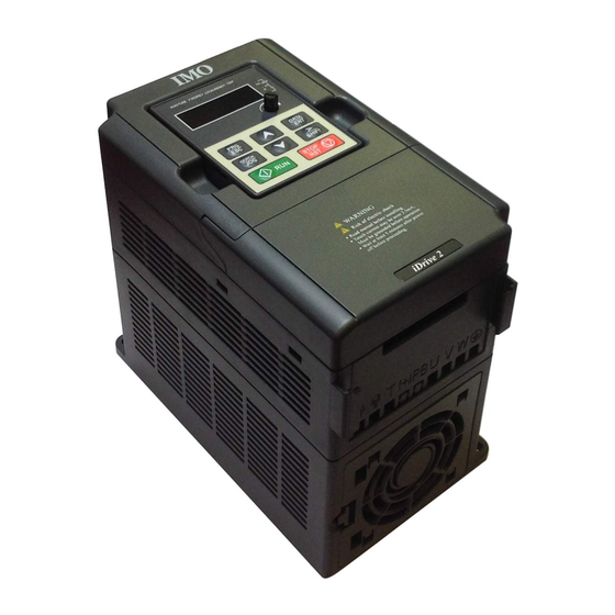
IMO iDrive2 XKL
Thank you for purchasing our iDrive2 XKL series of inverters.
• This product is designed to drive a three-phase induction motor. Read through this instruction manual and be familiar with
the handling procedure for correct use.
• Improper handling might result in incorrect operation, a short life, or even a failure of this product as well as the motor.
• Deliver this manual to the end user of this product. Keep this manual in a safe place until this product is discarded.
• For how to use an optional device, refer to the instruction and installation manuals for that optional device.
IMO Precision Controls Ltd.
XKL-MANUAL
1
Advertisement
Table of Contents

Related Manuals for IMO iDrive2 XKL


Summary of Contents for IMO iDrive2 XKL
- Page 1 General application Inverter IMO iDrive2 XKL Thank you for purchasing our iDrive2 XKL series of inverters. • This product is designed to drive a three-phase induction motor. Read through this instruction manual and be familiar with the handling procedure for correct use.
- Page 2 All rights reserved. No part of this publication may be reproduced or copied without prior written permission from IMO Precision Controls Ltd. All products and company names mentioned in this manual are trademarks or registered trademarks of their respective holders.
-
Page 3: Table Of Contents
Content ......................Error! Bookmark not defined. 1 Safety Precautions ............................. 4 1.1 Safety definition ............................4 1.2 Warning symbols ............................ 4 1.3 Safety guidelines ............................ 4 2 Product overview ............................7 2.1 Quick start-up ............................7 2.2 Product specification ..........................8 2.3 Name plate ............................ -
Page 4: Safety Precautions
If ignored, physical injury or death may occur, or damage may occur to the devices. IMO are not responsible for any physical injury or death to persons or damage to the devices if the safety precautions in the manual are not complied with. - Page 5 iDrive2 inverters Safety Precautions The electrical parts and components inside the inverter are electrostatic. Take precautions to avoid electrostatic discharge during relevant operation. 1.3.1 Delivery and installation Please install the inverter on fire-retardant material and keep the inverter away from combustible materials.
- Page 6 iDrive2 inverters Safety Precautions time designated on the inverter after disconnection. Take measures to avoid screws, cables and other conductive matters to falling into the inverter during maintenance and component replacement. Note: Ensure screws are tightened to the correct torque. ...
-
Page 7: Product Overview
iDrive2 inverters Product overview 2 Product overview 2.1 Quick start-up 2.1.1 Unpacking inspection Check as followings after receiving products: 1. Check that there is no physical or water damage to the package. Contact supplier immediately if received damaged. 2. Check the information on the type designation label on the outside of the package to verify that the drive is of the correct type. -
Page 8: Product Specification
iDrive2 inverters Product overview 2. Check that the accessories of the inverter are correctly and properly installed. The installation cables should meet the needs of every component (including reactors, input filters, output reactors, output filters, DC reactors and braking resistors). 3. - Page 9 iDrive2 inverters Product overview Function Specification resolution Terminal analog input ≤ 20mV resolution Analog input 1 input 0~10V/0~20mA Analog output 1 input 0~10V/0~20mA Digital input 5 common input 1 Y output (commonly used with digital output) and 1 Digital output programmable relay output Communication 485 communication...
-
Page 10: Name Plate
iDrive2 inverters Product overview 2.3 Name plate Fig 2-1 Name plate 2.4 Type designation key The type designation contains information on the inverter. The user can find the type designation on the type designation label attached to the inverter or the simple name plate. XKL –... -
Page 11: Structure Diagram
iDrive2 inverters Product overview 2.6 Structure diagram Below is the layout figure of the inverter (take the inverter of 2.2kW as the example). Fig 2-3 Product structure diagram Serial No. Name Illustration See Keypad Operation Procedure for detailed information Keypad Protects the internal parts and components Cover POWER indicator... -
Page 12: Installation Guidelines
The installation and design of the inverter should be comply with the requirement of the local laws and regulations at the installation site. If the installation infringes the requirement, IMO will exempt from any responsibility. Additionally, if users do not comply with the recommendation, some damage beyond the assured maintenance range may occur. - Page 13 Installation direction effect. Note: IMO XKL series inverters should be installed in a clean and well ventilated environment according to enclosure classification. Cooling air must be clean, free from corrosive materials and electrically conductive dust. 3.1.2 Installation direction The inverter may be installed on the wall or in a cabinet.
-
Page 14: Standard Wiring
iDrive2 inverters Installation Guidelines 3.1.4 Installation space Fig 3-2 Installation space Note: Fan cooled drives can be mounted side by side, natural cooled drives require 30mm clearance (Dim A) A minimum clearance of 100mm is required above and below the drive (Dim B). 3.2 Standard wiring 3.2.1 Connection diagram of main circuit Diagram 3-3 Connection diagram of main circuit... - Page 15 iDrive2 inverters Installation Guidelines Terminal Terminal name Function sign Grounding terminal Each machine has a standard PE terminal. Note: Do not use an asymmetrically constructed motor cable. If there is a symmetrically constructed grounding conductor in the motor cable in addition to the conductive shield, connect the grounding conductor to the grounding terminal at the inverter and motor ends.
-
Page 16: Layout Protection
iDrive2 inverters Installation Guidelines Fig 3-6 Wiring of control circuit Description Output relay N/O terminal (Relay contact rating: 3A/AC250V,1A/DC30V) Output relay common terminal +10V Local power supply +10Vdc for analog inputs. 1. Input range: AI voltage and current: 0~10V/0~20mA and switch by J3 2. - Page 17 iDrive2 inverters Installation Guidelines If the inverter is connected to multiple motors, a separate thermal overload switch or a circuit breaker must be used for protecting each cable and motor. These devices may require a separate fuse for protection. 3.3.3 Implementing a bypass connection It may be necessary to set power frequency and variable frequency conversion circuits for the assurance of continuous normal work of the inverter if faults.
-
Page 18: Keypad Operation Procedure
Keypad Operation Procedure 4 Keypad Operation Procedure The keypad is used to control iDrive2 XKL series inverters, display active data and adjust parameters. Fig 4-1 Keypad Note: Fix the external keypad with M3 screws or the installation bracket. The installation bracket is optional. -
Page 19: Keypad Displaying
Quick key P07.02. 4.1 Keypad display The keypad display of IMO XKL series inverters is divided into stopped state parameter, running state parameter, function code parameter editing state and fault alarm state etc. 4.1.1 Display state of stopped parameter When the inverter is in the stopped state, the keypad will display stop parameters which is shown in figure 4-2. -
Page 20: Keypad Operation
iDrive2 inverters Keypad Operation Procedure In the stopped state, various kinds of parameters can be displayed. Select the parameters to be displayed or not by P07.07. See the instructions of P07.07 for the detailed definition of each setting. In the stopped state, there are 14 stopped parameters can be selected to be displayed or not. They are: set frequency, bus voltage, input terminals state, output terminals state, PID reference, PID feedback, AI1, AI2 and the current stage of multi-stage speeds, pulse counting value. - Page 21 Fig 4-4 Flow diagram of password setting 4.2.3 How to monitor the inverter state through function codes IMO XKL series inverters provide group P17 as the state inspection group. Users can enter into P17 directly to monitor the state. Fig 4-5 Flow diagram of state monitoring...
-
Page 22: Function Parameters
Function Parameters 5 Function Parameters The function parameters of iDrive2 XKL series inverters have been divided into 30 groups (P00~P29) according to the function, of which P18~P28 are reserved. Each function group contains certain function codes applying 3-level menus. For example, “P08.08” means the eighth function code in the P8 group function, P29 group is factory reserved, and users are unable to access these parameters. - Page 23 iDrive2 inverters Function Parameters Function Default Name Detailed instruction of parameters Modify value code Selects the run command method of the inverter. The control command of the inverter includes: start, stop, forward, reverse, jogging and fault reset. 0:Keypad run command method (“LOCAL/REMOT” light off) Run command control by RUN, STOP/RST on the keypad.
- Page 24 iDrive2 inverters Function Parameters Function Default Name Detailed instruction of parameters Modify value code command 2:Analog AI2 setting selection Analog input terminal sets the frequency. There are 2 standard analog input terminal, of which AI1 is adjusted through digital potentiometer, AI2 (0~10V/0~20mA) this is set by the jumper.
- Page 25 ACC time 1 ○ 0Hz. on model Time (secs) to ramp down from Max frequency (P00.03) to 0Hz. IMO XKL series inverters define four groups of Depend ACC/DEC time which can be selected by P05. The P00.12 DEC time 1 ○...
- Page 26 iDrive2 inverters Function Parameters Function Default Name Detailed instruction of parameters Modify value code The relationship table of the motor type and carrier frequency: Motor type The factory value of carrier frequency 0.2~2.2kW 4kHz The advantage of high carrier frequency: ideal current waveform, little current harmonic wave and motor noise.
- Page 27 iDrive2 inverters Function Parameters Function Default Name Detailed instruction of parameters Modify value code Restoring to the default value will cancel the user password, please use this function with caution. P01 Group Start-up and stop control 0:Start-up directly:start from the starting frequency P01.01 1:Start-up after DC braking: start the motor from the P01.00...
- Page 28 iDrive2 inverters Function Parameters Function Default Name Detailed instruction of parameters Modify value code starting the percentage of the rated current of the inverter. The setting range of P01.03: 0.0~100.0% The setting range of P01.04: 0.0~50.0s The changing mode of the frequency during start-up and ACC/DEC running.
- Page 29 iDrive2 inverters Function Parameters Function Default Name Detailed instruction of parameters Modify value code During the procedure of switching FWD/REV rotation, set the threshold by P01.14, which is as the table below: Dead time of P01.13 FWD/REV 0.00s ○ rotation Setting range: 0.0~3600.0s Switching Set the threshold point of the inverter:...
- Page 30 iDrive2 inverters Function Parameters Function Default Name Detailed instruction of parameters Modify value code automatically. Sets the hibernation delay time. When the running frequency of the inverter is lower than the lower limit one, the inverter will pause to stand by. Hibernation When the set frequency is above the lower limit for P01.20...
- Page 31 iDrive2 inverters Function Parameters Function Default Name Detailed instruction of parameters Modify value code Asynchronou P02.02 s motor rated 0.01Hz~P00.03 (the Max. frequency) 50.00Hz ◎ frequency Asynchronou Depend P02.03 s motor rated 1~36000rpm ◎ on model speed Asynchronou Depend P02.04 s motor rated 0~1200V ◎...
- Page 32 100.0% ○ protection coefficient Setting range: 20.0%~120.0% P04 Group V/F control DefineS the V/F curve of IMO XKL motor to meet the need of different loads. Motor V/F P04.00 0:Straight line V/F curve;applying to the constant torque ◎ curve setting...
- Page 33 iDrive2 inverters Function Parameters Function Default Name Detailed instruction of parameters Modify value code and the current of the inverter will increase the temperature of the inverter and decrease the efficiency. When the torque boost is set to 0.0%, the inverter is automatic torque boost.
- Page 34 iDrive2 inverters Function Parameters Function Default Name Detailed instruction of parameters Modify value code This function code is used to compensate the change of 380V: the rotation speed caused by load during running and 100.0% improve the stability of the motor. It can be set to the rated slip frequency of the motor which is calculated as below: Motor V/F...
- Page 35 iDrive2 inverters Function Parameters Function Default Name Detailed instruction of parameters Modify value code S3 terminals 6: Coast to stop P05.03 function 7: Fault reset ◎ selection 8: Operation pause 9: External fault input S4 terminals 10:Increasing frequency setting(UP) P05.04 function ◎...
- Page 36 iDrive2 inverters Function Parameters Function Default Name Detailed instruction of parameters Modify value code The function code sets the polarity of the input terminals. Set Value according to normal/inverse switching requirements. Normal = Inverse = Value Polarity selection of P05.10 0x000 ○...
- Page 37 iDrive2 inverters Function Parameters Function Default Name Detailed instruction of parameters Modify value code Enable the input function of virtual terminals at the Virtual communication mode. P05.12 terminals ◎ 0:Virtual terminals is invalid setting 1:MODBUS communication virtual terminals are valid Set the operation mode of the terminals control 0:2-wire control 1, comply the enable with the direction.
- Page 38 iDrive2 inverters Function Parameters Function Default Name Detailed instruction of parameters Modify value code terminal P05.17 0.000s ○ switching off delay time S3 terminal P05.18 switching on 0.000s ○ delay time terminal P05.19 0.000s ○ switching off delay time S4 terminal P05.20 switching on 0.000s...
- Page 39 iDrive2 inverters Function Parameters Function Default Name Detailed instruction of parameters Modify value code limit of AI1 AI1 input P05.36 0.100s ○ filter time Lower limit of P05.37 0.00V ○ Input filter time: this parameter is used to adjust the Correspondi sensitivity of the analog input.
- Page 40 iDrive2 inverters Function Parameters Function Default Name Detailed instruction of parameters Modify value code 12:Ready for operation 14:Overload pre-alarm 15: Underload pre-alarm 16:Completion of simple PLC stage 17:Completion of simple PLC cycle 18:Setting count value arrival 19:Defined count value arrival 20:External fault valid 22:Running time arrival 23:MODBUS communication virtual terminals output...
- Page 41 iDrive2 inverters Function Parameters Function Default Name Detailed instruction of parameters Modify value code motor) 6:Output voltage 7:Output power 8:Set torque value 9:Output torque 10:Analog AI1 input value 11:Analog AI2 input value 14:MODBUS communication set value 1 15:MODBUS communication set value 2 Lower limit of The above function codes define the relative relationship P06.17...
- Page 42 iDrive2 inverters Function Parameters Function Default Name Detailed instruction of parameters Modify value code passwords. Retreat editing state of the function codes and the password protection will become valid in 1 minute. If the password is available, press PRG/ESC to enter into the editing state of the function codes, and then “0.0.0.0.0”...
- Page 43 iDrive2 inverters Function Parameters Function Default Name Detailed instruction of parameters Modify value code Select the stop function by STOP/RST. STOP/RST is valid in any state for the fault reset. STOP/RST 0:Only valid for the panel control P07.04 ○ stop function 1:Valid for both panel and terminals control 2:Valid for both panel and communication control 3:Valid for all control modes...
- Page 44 iDrive2 inverters Function Parameters Function Default Name Detailed instruction of parameters Modify value code BIT8:analog AI2 value(V on) BIT11:current stage in multi-stage speed BIT12:pulse counters Frequency 0.01~10.00 P07.08 display 1.00 ○ Displayed frequency=run frequency* P07.08 coefficient Rotation 0.1~999.9% P07.09 speed Mechanical rotation speed =120*displayed run 100.0% ○...
- Page 45 iDrive2 inverters Function Parameters Function Default Name Detailed instruction of parameters Modify value code code 3 Factory bar P07.24 0x0000~0xFFFF ● code 4 Factory bar P07.25 0x0000~0xFFFF ● code 5 Factory bar P07.26 0x0000~0xFFFF ● code 6 Current fault 0:No fault P07.27 ●...
- Page 46 iDrive2 inverters Function Parameters Function Default Name Detailed instruction of parameters Modify value code Output P07.36 current at 0.0A ● current fault Bus voltage P07.37 at current 0.0V ● fault The Max. temperature 0.0℃ P07.38 ● at current fault Input terminal state P07.39 ●...
- Page 47 iDrive2 inverters Function Parameters Function Default Name Detailed instruction of parameters Modify value code temperature at the previous fault Input terminals P07.47 ● state at the previous fault Output terminals P07.48 ● state at the previous fault Previous 2 P07.49 fault runnig 0.00Hz ●...
- Page 48 Refer to P00.11 and P00.12 for detailed definition. Depend P08.00 ACC time 2 ○ IMO XKL series selects four groups of ACC/DEC time on model which can be selected by P5 group. The first group of Depend ACC/DEC time is the factory default.
- Page 49 iDrive2 inverters Function Parameters Function Default Name Detailed instruction of parameters Modify value code Traverse range: The traverse running is limited by upper and low frequency. The traverse range relative to the center frequency: traverse range AW=center frequency×traverse range P08.15. Sudden jumping frequency =...
- Page 50 iDrive2 inverters Function Parameters Function Default Name Detailed instruction of parameters Modify value code Setting range of P08.25:P08.26~65535 Setting range of P08.26:0~P08.25 Pre-set running time of the inverter. When the accumulative running time reaches the set time, the Setting P08.27 multi-function digital output terminals will output the ○...
- Page 51 iDrive2 inverters Function Parameters Function Default Name Detailed instruction of parameters Modify value code detection terminal will output the signal of “frequency arrival”, see value the diagram below for detailed information: The setting range:0.00Hz~P00.03(the Max. frequency) Used to control the internal braking resistor. Energy 0:Disabled P08.37...
- Page 52 iDrive2 inverters Function Parameters Function Default Name Detailed instruction of parameters Modify value code 0x000~0x1223 LED ones: frequency enable selection 0:∧ /∨ keys adjustments are valid 1:Reserved 2: ∧/∨ keys adjustments are invalid 3: Reserved LED tens: frequency control selection 0:Only valid when P00.06=0 or P00.07=0 1:Valid for all frequency setting manner Keypad data...
- Page 53 iDrive2 inverters Function Parameters Function Default Name Detailed instruction of parameters Modify value code DOWN terminal 0.50 P08.46 0.01~50.00 Hz/s ○ frequency Hz/s integral ratio 0x000~0x111 LED ones: The action selection when the digital adjusting the frequency is off. 0:Save when the power is off 1:Clear when the power is off Action when LED tens:The action selection when MODBUS set...
- Page 54 iDrive2 inverters Function Parameters Function Default Name Detailed instruction of parameters Modify value code P09 Group PID control When the frequency command selection (P00.06, P00. 07) is 7, the running mode of the inverter is procedure PID control. The parameter determines the “set value” during the PID procures.
- Page 55 iDrive2 inverters Function Parameters Function Default Name Detailed instruction of parameters Modify value code P determines the strength of the whole PID adjuster. The parameter of 100 means that when the offset of PID feedback and reference value is 100%, the adjusting range of PID adjustor is the Max.
- Page 56 iDrive2 inverters Function Parameters Function Default Name Detailed instruction of parameters Modify value code Setting range:0.0~100.0% Output upper These parameters are used to set the upper and lower P09.09 100.0% ○ limit of PID limit of the PID adjustor output. 100.0 % corresponds to Max.
- Page 57 Multi-stage can be P10.14 0.0% ○ speed 6 IMO XKL series inverters can set 16 stages speed, selected by the combination of multi-stage terminals Multi-stage P10.16 0.0% ○ 1~4, corresponding to the speed 0 to speed 15. speed 7 Multi-stage P10.18...
- Page 58 iDrive2 inverters Function Parameters Function Default Name Detailed instruction of parameters Modify value code Multi-stage Select at most 16 stages speed via the combination P10.28 0.0% ○ speed 13 code of S1, S2, S3, and S4. The start-up and stopping of multi-stage running is Multi-stage P10.30 0.0%...
- Page 59 iDrive2 inverters Function Parameters Function Default Name Detailed instruction of parameters Modify value code 2. Prohibition of input phase protection can enable this function. 0:Disabled 1:Enabled Overvoltage P11.03 speed loss ○ protection Overvoltage 120~150%(standard bus voltage)(400V) 140% speed loss P11.04 ○...
- Page 60 iDrive2 inverters Function Parameters Function Default Name Detailed instruction of parameters Modify value code test level Setting range of P11.08: Enable and define the overload pre-alarm of the inverter or the motor. Setting range: 0x000~0x131 LED ones: 0:Overload pre-alarm of the motor, comply with the rated current of the motor 1:Overload pre-alarm of the inverter, comply with the rated current of the inverter...
- Page 61 iDrive2 inverters Function Parameters Function Default Name Detailed instruction of parameters Modify value code Select the action of fault output terminals on undervoltage and fault reset. Output 0x00~0x11 terminal LED ones: P11.13 action 0:Action under fault undervoltage 0x00 ○ selection 1:No action under fault undervoltage during fault LED tens:...
- Page 62 iDrive2 inverters Function Parameters Function Default Name Detailed instruction of parameters Modify value code 4: Odd check (E,8,2) for RTU 5:Even check(O,8,2) for RTU 0~200ms It means the interval time between the in time the drive receives the data and sends it to the upper monitor. If the Communicati answer delay is shorter than the system processing time, P14.03...
- Page 63 iDrive2 inverters Function Parameters Function Default Name Detailed instruction of parameters Modify value code P17 Group Monitoring function Display current set frequency of the inverter P17.00 0.00Hz ● frequency Range: 0.00Hz~P00.03 Output Display current output frequency of the inverter 0.00Hz P17.01 ●...
- Page 64 iDrive2 inverters Function Parameters Function Default Name Detailed instruction of parameters Modify value code AI1 input Display analog AI1 input signal P17.19 0.00V ● voltage Range: 0.00~10.00V AI2 input Display analog AI2 input signal 0.00V P17.20 ● voltage Range: 0.00~10.00V AI3 input Display analog AI2 input signal 0.00V...
-
Page 65: Fault Tracking
Fault tracking 6 Fault tracking 6.1 Maintenance intervals If installed in an appropriate environment, the inverter requires very little maintenance. The table lists the routine maintenance intervals recommended by IMO. Checking part Checking item Checking method Criterion Check the ambient... - Page 66 iDrive2 inverters Fault tracking Checking part Checking item Checking method Criterion Ensure that there is no Terminals seat Visual examination damage Ensure that there is no leakage, color-change, Visual examination cracking or case expansion. Estimate the usage time according to Filter capacitors Ensure the safety valve the maintenance or...
- Page 67 Fan failure can be predicted by the increasing noise from the fan bearings. If the inverter is operated in a critical part of a process, fan replacement is recommended once these symptoms appear. Replacement fans are available from IMO. Read and follow the instructions in chapter Safety Precautions. Ignoring the instructions would cause physical injury or death, or damage to the equipment.
-
Page 68: Fault Solution
Read and follow the instructions in chapter Safety Precautions. Ignoring the instructions may cause physical injury or death, or damage to the equipment. Replace electrolytic capacitors after 35000 hours operation. Please contact IMO for assistance. 6.1.3 Power cable Read and follow the instructions in chapter Safety Precautions. Ignoring the instructions may cause physical injury or death, or damage to the equipment. - Page 69 3. See the following table for possible cause and remedial action. 4. Remove fault, if error still exists, consult IMO.. 5. Check to eliminate the fault and carry out fault reset to run the inverter.
- Page 70 iDrive2 inverters Fault tracking Fault code Fault type Possible cause Remedy action Refer to the overcurrent solution Rectifier overheat 1. Air duct jam or fan damage 2. Ensure fan is clean and not clogged. 2. Ambient temperature is too high. 3.
-
Page 71: Communication Protocol
iDrive2 inverters Communication protocol 7 Communication protocol 7.1 Brief instruction to Modbus protocol Modbus protocol is a software protocol and common language which is applied in the electrical controller. With this protocol, the controller can communicate with other devices via network (the channel of signal transmission or the physical layer, such as RS485). - Page 72 iDrive2 inverters Communication protocol It is recommended to use shield cables and make the shield layer as the grounding wires during RS485 remote communication. In the cases with less devices and shorter distance, it is recommended to use 120Ω terminal resistor as the performance will be weakened if the distance increase even though the network can perform well without load resistor.
- Page 73 iDrive2 inverters Communication protocol rate and digital check bit in RS485 should be the same and there should be no repeated address. 7.2.2 RTU mode 7.2.2.1 RTU communication frame format If the controller is set to communicate by RTU mode in Modbus network every 8bit byte in the message includes two 4Bit hex characters.
- Page 74 iDrive2 inverters Communication protocol T1-T2-T3-T4(transmission time of 3.5 bytes) 7.2.2.2 RTU communication frame error checkout Various factors (such as electromagnetic interference) may cause error in the data transmission. For example, if the sending message is a logic “1”,A-B potential difference on RS485 should be 6V, but in reality, it may be -6V because of electromagnetic interference, and then the other devices take the sent message as logic“0”.
-
Page 75: Rtu Command Code And Communication Data Illustration
iDrive2 inverters Communication protocol crc_value^=*data_value++; for (i=0;i<8;i++) if (crc_value&0x0001) crc_value=(crc_value>>1)^0xa001; else crc_value=crc_value>>1; return (crc_value); In ladder logic, CKSM calculated the CRC value according to the frame with the table inquiry. The method is advanced with easy program and quick calculation speed. But the ROM space the program occupied is huge. So use it with caution according to the program required space. - Page 76 iDrive2 inverters Communication protocol CRC occupies 2 bytes with the fact that the high bit is in the front and the low bit is in the behind. RTU slave response message (from the inverter to the master) START T1-T2-T3-T4 (transmission time of 3.5 bytes) ADDR Byte number Data high bit of address 0004H...
- Page 77 iDrive2 inverters Communication protocol RTU slave response message (from the inverter to the master) START T1-T2-T3-T4 (transmission time of 3.5 bytes) ADDR High bit of writing data address Low bit of writing data address High bit of data content Low bit of data content CRC CHK low bit CRC CHK high bit T1-T2-T3-T4 (transmission time of 3.5 bytes)
- Page 78 iDrive2 inverters Communication protocol 7.3.4.1 The rules of parameter address of the function codes The parameter address occupies 2 bytes with the fact that the high bit is in the front and the low bit is in the behind. The range of high and low byte are: high byte—00~ffH; low byte—00~ffH. The high byte is the group number before the radix point of the function code and the low byte is the number after the radix point.
- Page 79 =1:overload pre-alarm Bit5~ Bit6:=00:keypad control =01:terminal control =10:communication control Fault code of the 2102H See the fault type instruction inverter Identifying code of the 2103H IMO XKL-----0x010d inverter Setting frequency 3001H Bus voltage 3002H Output voltage 3003H Output current 3004H...
- Page 80 Note: the code is consisted of 16 bit which is high 8 bits and low 8 bits. High 8 bits mean the motor type series and low 8 bits mean the derived motor types of the series. For example, 0110H means IMO XKL vector inverters.
- Page 81 iDrive2 inverters Communication protocol If Modbus communication is used to control the hibernation restore delay time as 5.0s. Firstly, 5.0 can be magnified by 10 times to integer 50 (32H) and then this data can be sent. After the inverter receives the command, it will change 50 into 5 according to the fieldbus ratio value and then set the hibernation restore delay time as 5s.
- Page 82 iDrive2 inverters Communication protocol Password When the upper monitor is writing or reading and the user password is set protection without password unlocking, it will report that the system is locked. The slave uses functional code fields and fault addresses to indicate it is a normal response or some error occurs (named as objection response).
- Page 83 iDrive2 inverters Communication protocol If the response message is as below: See from the returned data, all fault types are 0023H (decimal 35) with the meaning of maladjustment (STo). 7.3.7.2 Example of writing command 06H Make the inverter with the address of 03H to run forward. See table 1, the address of “communication control command”...
-
Page 84: Appendix A Technical Data
iDrive2 inverters Appendix A Technical data Appendix A Technical data A.1 Ratings A.1.1 Capacity Inverter sizing is based on the rated motor current and power. To achieve the rated motor power reference in the table, the rated current of the inverter must be higher than or equal to the rated motor current. Also the rated power of the inverter must be higher than or equal to the rated motor power. -
Page 85: Emc Regulations
iDrive2 inverters Appendix A Technical data A.2.2 Compliance with the European EMC Directive The EMC Directive defines the requirements for immunity and emissions of electrical equipment used within the European Union. The EMC product standard (EN 61800-3:2004) covers requirements stated for drives. See section EMC regulations A.3 EMC regulations EMC product standard (EN 61800-3:2004) contains the EMC requirements to the inverter. -
Page 86: Appendix B Dimension Drawings
Appendix B Dimension drawings Appendix B Dimension drawings Dimension drawings of the IMO XKL are shown below. The dimensions are in mm. B.1 Keypad structure The keypad can be installed on the (optional) installation bracket. B.2 Inverter dimensions... -
Page 87: Appendix C Peripherial Options And Parts
Appendix C Peripherial options and parts Appendix C Peripherial options and parts This chapter describes how to select the options and parts of IMO XKL series inverters. C.1 Peripherial wiring Below is the peripherial wiring of IMO XKL series inverters. -
Page 88: Power Supply
iDrive2 inverters Appendix C Peripherial options and parts Pictures Name Description Cables Device to transfer the electronic signals Extend the effective transimiting distance of the Output reactor inverter to control the sudden high voltage when switchiong on/off the IGBT of the inverter. C.2 Power supply ... -
Page 89: Reactors
In order to avoid the damage of the motor insulation, it is necessary to add reactor compensation. Inverter Model Input reactor Output reactor XKL-040-21 Consult IMO Consult IMO XKL-075-21 Consult IMO Consult IMO XKL-150-21... -
Page 90: Braking System
Output filter filter can reduce the RFI noise caused by the cables between the inverter and the motor and the leakage current of the conducting cables. C3 Filter The inverter Input filter Output filter XKL-040-21 RFC3-3S Consult IMO XKL-075-21 RFC3-3S Consult IMO XKL-150-21 RFC3-10S Consult IMO XKL-220-21... - Page 91 Install all resistors in a place where they have air clearance. The materials near the brake resistor must be non-flammable. The surface temperature of the resistor can be extremely high, ensure sufficient ventilation for heat dissipation. Only external braking resistor is needed in IMO XKL.
-
Page 92: Appendix D Further Information
Appendix D Further information D.1 Product and service inquiries Address any inquiries about the product to IMO, quoting model type and serial number of the unit in question. D.2 Document library on the Internet You can find manuals and other product documents in PDF format on the Internet. Go to... - Page 93 IMO Precision Controls Ltd The purpose of this instruction manual is to provide accurate information in handling, setting up and operating of the iDrive2 XKL series of inverters. Please feel free to send your comments regarding any errors or omissions you may have found, or any suggestions you may have for generally improving the manual.
- Page 94 IMO Precision Controls Ltd. 1000 North Circular Road, Staples Corner, London, NW2 7JP England Phone: +44 (0)20 8452 6444 Fax: +44 (0)20 8450 2274 URL http://www.imopc.com 2015-01 S.Mc (Issue 3)
Need help?
Do you have a question about the iDrive2 XKL and is the answer not in the manual?
Questions and answers