Table of Contents
Advertisement
Instruction Manual
IMO Jaguar CUB
Thank you for purchasing our Jaguar CUB series of inverters.
• This product is designed to drive a three-phase induction motor. Read through this instruction
manual and be familiar with the handling procedure for correct use.
• Improper handling blocks correct operation or causes a short life or failure.
• Deliver this manual to the end user of the product. Keep this manual in a safe place until the
inverter is discarded.
• For the usage of optional equipment, refer to the manuals prepared for optional equipment.
IMO Precision Controls Ltd
Compact Inverter
Advertisement
Chapters
Table of Contents

Related Manuals for IMO Jaguar CUB


Summary of Contents for IMO Jaguar CUB
-
Page 1: Instruction Manual
Compact Inverter IMO Jaguar CUB Thank you for purchasing our Jaguar CUB series of inverters. • This product is designed to drive a three-phase induction motor. Read through this instruction manual and be familiar with the handling procedure for correct use. - Page 2 Copyright © 2003. IMO Precision Controls Ltd All rights reserved. No part of this publication may be reproduced or copied without prior written permission from IMO Precision Controls Ltd All products and company names mentioned in this manual are trademarks or registered trademarks of their respective holders.
- Page 3 Preface Thank you for purchasing our Jaguar CUB series of inverters. This product is designed to drive a three-phase induction motor. Read through this instruction manual and be familiar with the handling method for correct use. Improper handling blocks correct operation or causes a short life or failure.
-
Page 4: Safety Precautions
These safety precautions are of utmost importance and must be observed at all times. Application • Jaguar CUB is designed to drive a three-phase induction motor. Do not use it for sin- gle-phase motors or for other purposes. Fire or an accident could occur. - Page 5 • Do not support the inverter by its terminal block cover during transportation. Doing so could cause a drop of the inverter and cause injuries. • Prevent lint, paper fibers, sawdust, dust, metallic chips, or other foreign materials from getting into the inverter or from accumulating on the heat sink. Doing so could cause fire or an accident.
- Page 6 (Design the machinery or equipment so that human safety is ensured after restarting.) • If you set the function codes wrongly or without completely understanding this instruction manual and the Jaguar CUB User's Manual, the motor may rotate with a torque or at a speed not permitted for the machine.
- Page 7 • Do not turn the main circuit power on or off in order to start or stop inverter operation. Doing so could cause failure. • Do not touch the heat sink or braking resistor because they become very hot. Doing so could cause burns. •...
- Page 8 Conformity to the Low Voltage Directive in the EU If installed according to the guidelines given below, inverters marked with CE or TÜV are considered as compliant with the Low Voltage Directive 73/23/EEC. 1. The ground terminal G should always be connected to the ground. Do not use only a residual-current-operated protective device (RCD)/earth leakage circuit breaker (ELCB)* as the sole method of electric shock protection.
- Page 9 Conformity to the Low Voltage Directive in the EU (Continued) 11. Use wires listed in EN60204 Appendix C. Recommended wire size (mm Main circuit Appli- Rated current (A) Control power input [P1, cable circuit Inverter [L1/R, L2/S, L3/T] motor Inverter type P (+)] MCCB or RCD/ELCB (30A,...
- Page 10 Conformity to UL standards and Canadian standards (cUL certification) If installed according to the guidelines given below, inverters marked with UL/cUL are considered as compliant with the UL and CSA (cUL certified) standards. 1. Solid state motor overload protection (motor protection by electronic thermal overload relay) is provided in each model.
- Page 11 Conformity to UL standards and Canadian standards (cUL certification) (Continued) 6. Install UL certified fuses between the power supply and the inverter, referring to the table below. Required torque Wire size Ib-in (N·m) AWG or kcmil (mm Power supply Inverter type Control circuit Control circuit voltage...
-
Page 12: Precautions For Use
Precautions for use When driving a 400V general-purpose motor with an inverter Driving a 400V using extremely long wires, damage to the insulation of the general-purpose motor may occur. Use an output circuit filter (OFL) if neces- motor sary after checking with the motor manufacturer. When the inverter is used to run a general-purpose motor, the temperature of the motor becomes higher than when it is Torque charac-... - Page 13 Avoid such operation. Synchronous mo- It is necessary to take special measures suitable for this In running tors motor type. Contact IMO for details. special motors Single-phase motors are not suitable for inverter-driven variable speed operation. Use three-phase motors. Single-phase...
- Page 14 Do not mount power-factor correcting capacitors in the in- Discontinuance verter primary circuit. (Use the DC reactor to improve the of power-factor inverter power factor.) Do not use power-factor correcting correcting ca- capacitors in the inverter output circuit. An overcurrent trip pacitor will occur, disabling motor operation.
-
Page 15: How This Manual Is Organized
Chapter 9 LIST OF PERIPHERAL EQUIPMENT AND OPTIONS This chapter describes main peripheral equipment and options which can be connected to the Jaguar CUB series of inverters. Chapter 10 COMPLIANCE WITH STANDARDS This chapter describes standards with which the Jaguar CUB series of inverters comply. xiii... - Page 16 Icons The following icons are used throughout this manual. This icon indicates information which, if not heeded, can result in the inverter not operating to full efficiency, as well as information concerning incorrect operations and settings which can result in accidents. This icon indicates information that can prove handy when performing certain settings or operations.
-
Page 17: Table Of Contents
Standards (cUL certification).....10-1 3.6 Monitoring the Running Status-- 10.1.1 General ..........10-1 "Drive monitoring" ........3-16 10.1.2 Considerations when using Jaguar CUB 3.7 Checking I/O Signal Status-- in systems to be certified by UL and cUL "I/O checking" .......... 3-20 10-1 3.8 Reading Maintenance... - Page 18 10.5 Compliance with the Low Voltage Directive in the EU ..........10-5 10.5.1 General ........... 10-5 10.5.2 Points for Consideration when using the Jaguar CUB series in a system to be certified by the Low Voltage Directive in the EU ......10-5...
-
Page 19: Chapter 1 Before Using The Inverter
(a) Main nameplate (b) Sub nameplate Figure 1.1 Nameplates TYPE: Type of inverter CUB 1A5 - 4 E Code Series Name Code With integrated filter Jaguar CUB Code Applicable current rating Code Power supply 3 Amps Single-phase 200v 5 Amps Three-phase 200v... -
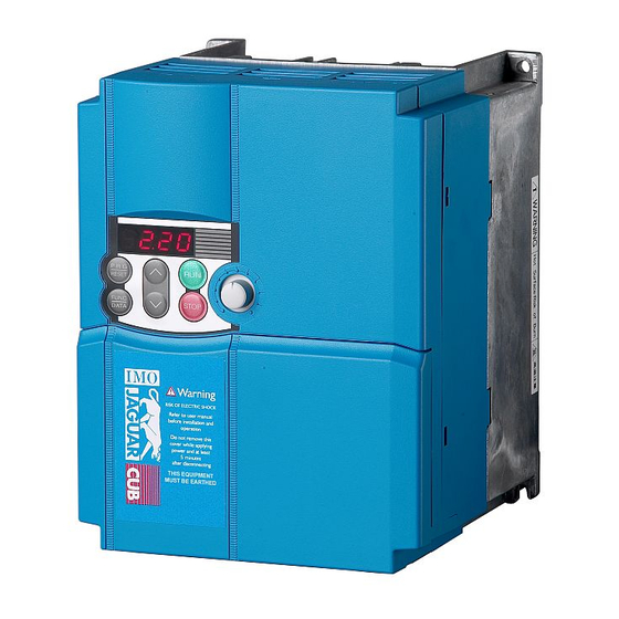
Page 20: External View And Terminal Blocks
Control circuit terminal bock cover Figure 1.2 External Views of Jaguar CUB (2) View of terminals Barrier for the RS485 communications port* Control signal cable port DB, P1, P (+) and N (-) wire port... -
Page 21: Storage Environment
1.4 Storage Environment 1.4.1 Temporary storage Store the inverter in an environment that satisfies the requirements listed in Table 1.1. Table 1.1 Environmental Requirements for Storage and Transportation Item Requirements Storage -25 to +70 C Locations where the inverter is not temperature * subject to abrupt changes in temperature that would result in the... -
Page 22: Chapter 2 Mounting And Wiring Of The Inverter
Chapter 2 Mounting and Wiring of the Inverter 2.1 Operating Environment Install the inverter in an environment that satisfies the requirements listed in Table 2.1. Table 2.2 Output Current Derating Factor in Table 2.1 Environmental Requirements Relation to Altitude Item Specifications Output current Altitude... -
Page 23: Wiring
(3) Mounting direction Secure the inverter to the mounting base with four screws or bolts (M4) so that the Jaguar CUB logo faces outwards. Tighten those screws or bolts perpendicular to the mounting base. Do not mount the inverter upside down or horizontally. Doing so will reduce the heat dissipation efficiency of the inverter and cause the overheat protection function to operate, so the inverter will not run. -
Page 24: Terminal Arrangement And Screw Specifications
2.3.2 Terminal Arrangement and Screw Specifications The figures below show the arrangement of the main and control circuit terminals which differs according to inverter type. The two terminals prepared for grounding, which are indicated by the symbol in Figures A to D, make no distinction between the power supply side (primary circuit) and the motor side (secondary circuit). -
Page 25: Recommended Wire Sizes
(2) Arrangement of the control circuit terminals (common to all Jaguar CUB models) FWD REV Screw size: M 2 Tightening torque: 0.2 N•m Screw size: M 2.5 Tightening torque: 0.4 N•m Table 2.4 Control Circuit Terminals Dimension of openings in... - Page 26 Table 2.6 Recommended Wire Sizes Recommended wire size (mm Main circuit Appli- cable Main circuit power input motor Inverter type [L1/R, L2/S, L3/T] Braking Control Inverter rating [L1/L, L2/N] resistor circuit output (kW) Grounding [ [P1, P (+)] [P (+), DB] [U, V, W] w/ DCR w/o DCR...
-
Page 27: Wiring Precautions
2.3.4 Wiring Precautions Follow the rules below when performing wiring for the inverter. (1) Make sure that the source voltage is within the rated voltage range specified on the nameplate. (2) Be sure to connect the power wires to the main circuit power input terminals L1/R, L2/S and L3/T (for three-phase voltage input) or L1/L and L2/N (for single-phase voltage input) of the inverter. -
Page 28: Wiring For Main Circuit Terminals And Grounding Terminals
2.3.5 Wiring for Main Circuit Terminals and Grounding Terminals Follow the procedure below. Figure 2.3 illustrates the wiring procedure with peripheral equipment. Wiring procedure Grounding terminals Inverter output terminals (U, V, and W) DC reactor connection terminals (P1 and P(+)) * Braking resistor connection terminals (P(+) and DB) * DC link circuit terminals (P(+) and N(-)) * Main circuit power input terminals (L1/R, L2/S and L3/T) or (L1/L and L2/N) - Page 29 The wiring procedure for the CUB5A-1 is given below as an example. For other inverter types, perform wiring in accordance with their individual terminal arrangement. (Refer to page 2-3.) Grounding terminals ( G) Be sure to ground either of the two grounding terminals for safety and noise reduction. All metal frames of electrical equipment must be grounded to avoid electric shock, fire and other disasters.
- Page 30 No output circuit filter inserted Output circuit filter inserted 5 m or less Power Power Output circuit filter supply supply Motor Motor Inverter Inverter 50 m or less 400 m or less • Do not connect a condensive capacitor or surge absorber to the inverter output ter- minals.
- Page 31 DC reactor terminals, P1 and P (+) Remove the jumper bar from terminals P1 and P(+). Connect a DC reactor (option) to terminals P1 and P(+), if required. • The wiring length should be 10 m or below. • If both a DC reactor and a braking resistor are to be connected to the inverter, secure both wires of the DC reactor and braking resistor together to terminal P(+).
- Page 32 DC link circuit terminals, P (+) and N (-) These are provided for the DC bus link circuit system. Connect these terminals with terminals P(+) and N (-) of other inverters. Consult IMO if these terminals are to be used. 2-11...
-
Page 33: Replacing The Main Circuit Terminal Block (Tb) Cover
Main circuit power input terminals, L1/R, L2/S, and L3/T (for three-phase voltage input) or L1/L and L2/N (for single-phase voltage input) 1) For safety, make sure that the molded case circuit breaker (MCCB) or magnetic contactor (MC) is turned off before wiring the main circuit power input terminals. -
Page 34: Wiring For Control Circuit Terminals
2.3.7 Wiring for Control Circuit Terminals Generally, the sheath of control circuit wires is not reinforced by any insulation. If the control circuit wires come into direct contact with the live main circuit terminal, therefore, the sheath may break. Accordingly, there is a possibility that high voltage on the main circuit may be applied to the control circuit wires. - Page 35 Table 2.8 Symbols, Names and Functions of the Control Circuit Terminals Symbol Name Functions [13] Potenti- Power supply (+10 VDC) for frequency command potentiometer (Potenti- ometer ometer: 1 to 5 k ) power Allowable output current: 10 mA supply [12] Voltage (1) The frequency is set according to the external analog input voltage.
- Page 36 - Since weak analogue signals are handled, these signals are especially susceptible to the external noise effects. Route the wiring as short as possible (within 20 m) and use shielded wires. In principle, ground the shielding layer of the shielded wires; if effects of external inductive noises are considerable, connection to terminal [11] may be effec- tive.
- Page 37 Table 2.8 Continued Symbol Name Functions [X1] Digital (1) The various signals such as coast-to-stop, alarm from external equip- input 1 ment, and multistep frequency selection can be assigned to terminals [X1] to [X3], [FWD] and [REV] by setting function codes E01 to E03, E98, [X2] Digital and E99.
- Page 38 If the jumper switch is set at SINK As shown in Figure 2.15, you can turn digital input terminals [X1] to [X3], [FWD], and [REV] on or off by open collector transistor outputs if you connect the power input (+) of the external device such as a programmable controller to termi- nal [PLC] that supplies power to...
- Page 39 Table 2.8 Continued Symbol Name Functions [FMA] Analog The monitor signal for analog DC voltage (0 to +10 VDC) is output. The monitor signal functions can be selected from the following with function code F31. - Output frequency (before slip compensation) - Output frequency (after slip compensation) - Output current - Output voltage...
-
Page 40: Switching Of Sink/Source (Jumper Switch)
Table 2.8 Continued Symbol Name Functions [30A], Alarm (1) Outputs a contact signal (SPDT) when a protective function has been [30B], relay activated to stop the motor. [30C] output Contact rating: 250 VAC 0.3A cos = 0.3 (for any +48 VDC, 0.5A fault) (2) A command similar to terminal [Y1] can be selected for the transistor output signal and use it for signal output. -
Page 41: Installing An Rs485 Communications Card (Option)
2.3.9 Installing an RS485 Communications Card (Option) When an optional RS485 communica- tions card is to be used, install it before replacing the main circuit TB cover. Align the card with the latch on the inverter and attach the card to the connector that is located above terminals [30A], [30B] and [30C]. -
Page 42: Cautions Relating To Harmonic Component, Noise, And Leakage Current
2.3.11 Cautions Relating to Harmonic Component, Noise, and Leakage Current (1) Harmonic component Input current to an inverter includes a harmonic component, which may affect other loads and condensive capacitors that are connected to the same power source as the inverter. If the harmonic component causes any problems, connect a DC reactor (option) to the inverter. -
Page 43: Chapter 3 Operation Using The Keypad
POT. In Alarm mode: Pressing this key displays information concerning the alarm code currently displayed on the LED monitor. * Jaguar CUB features three operation modes--Running, Programming, and Alarm modes. Refer to Section 3.2 "Overview of Operation Modes."... -
Page 44: Overview Of Operation Modes
Simultaneous keying Simultaneous keying means depressing two keys at the same time (expressed by "+"). Jaguar CUB supports simultaneous keying as listed below. (For example, the expression " keys" stands for pressing the key while holding down the key.) Operation modes... -
Page 45: Data Setting
3.2.2 Programming Mode Programming mode provides you with these functions--setting and checking function code data, monitoring maintenance information and checking input/output (I/O) signal status. The functions can be easily selected with the menu-driven system. Table 3.2 lists menus available in Programming mode. - Page 46 Limiting menus to be displayed The menu-driven system has a limiter function (specified by function code E52) that limits menus to be displayed for the purpose of simple operation. The factory default is to display Menu #1 "Data setting" only, allowing no switching to any other menu. Function Code E52 –...
- Page 47 Figure 3.2 Alarm Mode Status Transition...
- Page 48 3.3 Operation in Running Mode If the inverter is turned on, it automatically enters Running mode in which you may operate the following: (1) Run/Stop the Motor By factory default, pressing the key starts running the motor in the forward direction and pressing the key decelerates the motor to stop.
- Page 49 Setting the set frequency with the keys If you set function code F01 to "0: Keypad operation" and select frequency command 1, then the keys become enabled to set the set frequency in Running mode. In any other operation modes, those keys remain disabled. Pressing the key calls up the set frequency with the lowest digit blinking.
- Page 50 ■ Make setting under PID control To enable PID control, you need to set function code J01 to 1 or 2. Under the PID control, the items that can be set or checked with the keys are different from those under regular frequency control, depending upon the current LED monitor setting. If the LED monitor is set to the speed monitor (E43 = 0), you may access manual feed commands (Set frequency) with the keys;...
- Page 51 If you press the key in any conditions other than those described above, the following will appear: Frequency Frequency setting from Multistep fre- PID control can- command 1 Displayed using communica- quency setting celled (F01) tions link PID enabled Disabled Disabled Frequency setting by keypad Cancelled...
- Page 52 Figure 3.3 shows the procedure for selecting the desired monitor item. The speed monitor may display the output frequency (Hz), set frequency (Hz), load shaft speed (rpm), line speed (m/min.), and constant rate of feeding time (min.) which can be selected by setting up function code E48.
- Page 53 Table 3.4 lists the display items for the speed monitor that can be chosen with function code E48. (Refer to Chapter 5.) Table 3.4 Display Items on the Speed Monitor Function code Speed monitor items Meaning of Displayed Value E48 data Output frequency (before slip Before slip compensation compensation) (Hz)
-
Page 54: Setting The Function Codes Data Setting"
To set function codes in Menu #1 "Data setting," it is necessary to set function code E52 data to 0 (Function code data setting) or 2 (Full-menu mode). The table below lists the function codes available in the Jaguar CUB. The function codes are dis- played on the LED monitor on the keypad as shown below. - Page 55 Figure 3.4 shows the status transition for Menu #1 "Data setting" and Figure 3.5 shows an example of the function code data changing procedure. Figure 3.4 "Data Setting" Status Transition 3-13...
- Page 56 Basic key operation This section will give a description of the basic key operation, following the example of the function code data changing procedure shown in Figure 3.5. This example shows you how to change function code F01 data from the factory default "Enable the built-in potentiometer (F01 = 4)"...
-
Page 57: Checking Changed Function Codes Data Checking"
3.5 Checking Changed Function Codes--"Data checking" Menu #2 "Data checking" in Programming mode allows you to check function codes that have been changed. Only data that has been changed from the factory defaults are displayed on the LED monitor. You may refer to the function code data and change again if necessary. Figure 3.6 shows the status transition diagram for "Data checking."... -
Page 58: Monitoring The Running Status Drive Monitoring"
3.6 Monitoring the Running Status--"Drive monitoring" Menu #3 "Drive monitoring" is used to check the running status during maintenance and test running. The display items for "Drive monitoring" are listed in Table 3.6. Using keys, you may check those items in succession. Figure 3.7 shows the status transition diagram for "Drive monitoring." If you cannot switch the menu to any other one, set function code E52 data to 2 (Full-menu mode). - Page 59 Table 3.6 Drive Monitoring Display Items monitor Contents Unit Description shows: 3_00 Output Output frequency before slip compensation frequency 3_01 Output Output frequency after slip compensation frequency 3_02 Output Output current current 3_03 Output Output voltage voltage 3_05 Set frequency frequency 3_06 Running...
- Page 60 Displaying running status To display the running status in hexadecimal format, each state has been assigned to bit 0 to 15 as listed in Table 3.7. Table 3.8 shows the relationship between each of the status assignments and the LED monitor display. Table 3.9 gives the conversion table from 4-bit binary to hexadecimal. Table 3.7 Running Status Bit Allocation Notation Content Notation Content...
- Page 61 Hexadecimal expression A 16-bit binary number is expressed in hexadecimal format (4 digits). Table 3.9 shows the expres- sion. The hexadecimals are shown as they appear on the LED monitor. Table 3.9 Binary and Hexadecimal Conversion Binary Hexadecimal Binary Hexadecimal 3-19...
-
Page 62: Checking I/O Signal Status I/O Checking"
3.7 Checking I/O Signal Status--"I/O checking" With Menu #4 "I/O checking," you may display the I/O status of external signals without using a measuring instrument. External signals that can be displayed include digital I/O signals and analogueue I/O signals. Table 3.10 lists check items available. The status transition for I/O checking is shown in Figure 3.8. - Page 63 Table 3.10 I/O Check Items LED monitor Display contents Description shows: 4_00 I/O signals on the control Shows the ON/OFF state of the digital I/O terminals. circuit terminals Refer to " Displaying control I/O signal terminals " below for details on the display contents. Shows the ON/OFF state for the digital I/O terminals I/O signals on the control that received a command via RS485 communica-...
- Page 64 "0." Allocated bit data is displayed on the LED monitor in 4-digit hexadecimals ("0" to "F" each). With the Jaguar CUB, digital input terminals [FWD] and [REV] are assigned to bit 0 and bit 1, respectively. Terminals [X1] through [X3] are assigned to bits 2 through 4. The value "1" is set for each bit when the assigned input terminal is short-circuited with terminal [CM].
-
Page 65: Reading Maintenance Information--"Maintenance Information
3.8 Reading Maintenance Information--"Maintenance information" Menu #5 "Maintenance information" in Programming mode contains information necessary for performing maintenance on the inverter. Table 3.13 lists the maintenance information display items and Figure 3.9 shows the status transition for maintenance information. If you cannot switch the menu to any other one, set function code E52 data to 2 (Full-menu mode). Figure 3.9 "Maintenance Information"... - Page 66 Table 3.13 Maintenance Display Items LED Monitor Display contents Description shows: 5_00 Accumulated Shows the accumulated power-ON time of the inverter. run time Unit: thousands of hours. When the total ON-time is less than 10,000 hours (display: 0.001 to 9.999), it is possible to check data in hourly units. When the total time is 10,000 hours or more (display: 10.00 to 65.53), the display will change to units of 10 hours.
-
Page 67: Alarm Information
3.9 Reading Alarm Information--"Alarm information" Menu #6 "Alarm information" in Programming mode shows the cause of the past 4 alarms as alarm codes. Further, it is also possible to display alarm information that indicates the status of the inverter when the alarm occurred. Figure 3.10 shows the status transition of the alarm information and Table 3.14 lists the contents of the alarm information. - Page 68 Table 3.14 Alarm Information Contents LED monitor shows: Display contents Description (item No.) 6_00 Output frequency Output frequency before slip compensation 6_01 Output current Output current 6_02 Output voltage Output voltage 6_04 Set frequency Set frequency This shows the running direction being output. 6_05 Running direction F: normal;...
- Page 69 Table 3.14 Continued LED monitor shows: Display contents Description (item No.) Terminal I/O signal status under commu- nication control 6_18 (displayed with the ON/OFF of LED seg- ments) Shows the ON/OFF status of the digital I/O terminals under Terminal input signal status under commu- communication control.
-
Page 70: Chapter 4 Running The Motor
Chapter 4 RUNNING THE MOTOR 4.1 Running the motor for a test 4.1.1 Inspection and Preparation prior to the Operation Check the following prior to starting the operation. (1) Check if connection is correct. Especially check if the power wires are connected to inverter output terminals U, V and W and that the grounding wire is connected to the ground electrode correctly. -
Page 71: Preparation Before Running The Motor For A Test--Setting Function Code Data
4.1.3 Preparation before running the motor for a test--Setting function code data Before starting running the motor, set function code data specified in Table 4.1 to the motor ratings and your system design values. For the motor, check the rated values printed on the nameplate of the motor. -
Page 72: Test Run
4.1.4 Test run If the user sets the function codes wrongly or without completely understanding this Instruction Manual, the motor may rotate with a torque or at a speed not permitted for the machine. Accident or injury may result. Follow the descriptions of the previous Section 4.1.1, "Inspection and Preparation prior to the Operation"... -
Page 73: Chapter 5 Function Codes
FUNCTION CODES 5.1 Function Code Tables Function codes enable the Jaguar CUB series of inverters to be set up to match your system re- quirements. Each function code consists of a 3-letter string. The first letter is an alphabet that identifies its group and the following two letters are numerals that identify each individual code in the group. - Page 74 Electronic Thermal Overload F10 to F12 (Motor property selection, Overload detection level, and Thermal time constant) F10 through F12 set the thermal characteristics of the motor including the thermal time constant to simulate an overload status of the motor using the built-in elec- tronic thermal processing function of the inverter.
- Page 75 Using negative logic for programmable I/O terminals The negative logic signaling system can be used for the digital input and output terminals by setting the function codes specifying the properties for those terminals. Negative logic refers to inverted ON/OFF (logical value 1 (true)/0 (false)) state of input or output signal. An ON-active signal (the function takes effect if the terminal is short-circuited.) in the normal logic system is functionally equivalent to OFF-active signal (the function takes effect if the terminal is opened.) in the negative logic system.
- Page 76 The following tables list the function codes available for the Jaguar CUB series of inverters. F codes: Fundamental Functions *1 "Standard torque boost," "Nominal rated current of standard motor," and "Nominal rated capacity of standard motor" differ depending upon the rated input voltage and rated capacity. Refer to Table 5.1 “Standard Motor Parameters" on page 5-12.
- Page 78 E codes: Extension Terminal Functions...
- Page 79 (Note) Function codes E45 to E47 appear on the LED monitor; however, the Jaguar CUB series of inverters does not recognize these codes. *1 “Standard torque boost," "Nominal rated current of standard motor," and "Nominal rated capacity of standard motor"...
- Page 81 C codes: Control Functions of Frequency...
- Page 82 P codes: Motor Parameters H codes: High Performance Functions * "Standard torque boost," "Nominal rated current of standard motor," and "Nominal rated capacity of standard motor" differ depending upon the rated input voltage and rated capacity. Refer to Table 5.1 “Standard Motor Parameters" on page 5-12.
- Page 83 (Note) Function codes H71 and H95 appear on the LED monitor; however, the Jaguar CUB series of inverters does not recognize these codes. J codes: Application Functions 5-10...
- Page 84 y codes: Link Functions 5-11...
- Page 85 * The table below lists the factory settings of "standard torque boost," "Nominal rated current of standard motor," and "Nominal rated capacity of standard motor" in the "Default setting" column of the above tables. Table 5.1 Standard Motor Parameters Nominal rated Standard value Nominal rated current of capacity of standard...
-
Page 86: Overview Of Function Codes
5.2 Overview of Function Codes This section provides an overview of the function codes frequently used for the Jaguar CUB series of inverter. Data Protection Specifies whether function code data is to be protected from being accidentally changed by keypad operation. If data protection is enabled (F00 = 1), operation to change data is disabled so that no function code data, except F00 data, can be changed from the keypad. - Page 87 Running/Stopping and Rotational Direction Selects a source issuing a run command--keypad or external control signal input. - If F02 = 0, 2, or 3, the inverter can run the motor by the keys on the built-in keypad. The motor rotational direction can be specified in two ways, ei- ther by control signal input (F02 = 0) or by use of prefixed forward or reverse rotation (F02 = 2 or 3).
- Page 88 Maximum Frequency Sets the maximum frequency to drive the motor. Setting the frequency out of the range rated for the equipment driven by the inverter may cause damage or a dan- gerous situation. Set a maximum frequency appropriate for the equipment. For high-speed motors, it is recommended that the carrier frequency be set to 15 kHz.
- Page 89 Non-linear V/f pattern for voltage (H51) Sets the non-linear V/f pattern for voltage component. If the rated voltage at base frequency (F05) is set to 0, the data settings of function codes H50 and H51 will be ignored. If you set the data of H50 to 25 Hz or lower (Operation under low base frequency), the inverter output voltage may be limited.
- Page 90 Torque Boost Load Selection/Auto Torque Boost/Auto Energy Saving Operation In general, there are two different properties of loads--the torque load which is in- versely proportional to the square of speed (fans and pumps) and the constant torque load (industrial machinery). You can select a V/f pattern optimized to the load property.
- Page 91 Auto energy saving operation This feature controls the terminal voltage of the motor automatically to minimize the motor power loss. (Note that this feature may not be effective depending upon the motor characteristics. Check the characteristics before using this feature.) The inverter enables this feature for constant speed operation only.
- Page 92 - Trip immediately (F14 = 0) If an instantaneous power failure occurs when the inverter is in Running mode so that the inverter detects undervoltage of the DC link circuit, then the inverter im- mediately stops its output and displays the undervoltage alarm " "...
- Page 93 This setting is optimal for operations in which the motor speed quickly slows down to 0 rpm due to the heavy load with a very small moment of inertia if the motor coasts to a stop because of the instantaneous power failure. •...
- Page 94 Set the upper and lower frequencies correctly; otherwise, the inverter may not operate. Maintain the following relationship: (Upper frequency) > (Lower frequency), (Starting frequency), (Stop frequency) (Lower frequency) < (Maximum frequency) Bias (for Frequency Command 1) Bias (Bias reference point for frequency command 1) C32, C34 Analogue Input Adjustment (Gain and gain reference point for terminal input [12]) C37, C39...
- Page 95 When using the function codes for setting a gain or bias alone without changing any reference points, the setting procedure for the function codes is the same as that of IMO's conventional inverter models. F20 to F22 DC Braking (Starting frequency, Braking level, and Braking time) These function codes enable the DC braking to prevent the motor from coasting due to its inertia while it is decelerating to a stop.
- Page 96 For three-phase 200V and single-phase 200V series inverters The braking level setting for the three-phase 200V and single-phase 200V series should be calculated from the DC braking level I (A) based on the reference current I (A), as shown below. Setting (Example) Setting the braking level I at 4.2 Amp (A) for 0.75 kW stan-...
- Page 97 Lowering the carrier frequency increases the ripple components (har- monic components) on the output current waveform so as to increase the motor's power loss and raises the temperature of the motor. If the carrier frequency is set at 0.75 kHz, for example, estimate the motor output torque at 85% or less of the rated motor torque.
- Page 98 For three-phase 200V and single-phase 200V series of inverters Outputting the output current in an analogue format (FMA) (F31 = 2) The analogue output terminal [FMA] outputs 10 V, that is, 200% of the reference current I (A), supposing the output gain selected with F30 as 100%.
- Page 99 F43, F44 Current Limiter (Operation condition and Limiting level) F43 enables or disables the current limiter. If it is enabled, the inverter controls the output frequency while keeping the current set to F44 in order to prevent the motor from stalling. With F43, you may select whether the current limiter works during constant speed operation only (F43 = 1) or during both acceleration and constant speed operation (F43 = 2).
- Page 100 F50, F51 Electronic Thermal (Discharging capability and Allowable average loss) These function codes configure the electronic thermal overload relay to protect the braking resistor from overheating. Set the discharging capability and allowable average loss to F50 and F51, respec- tively. Those values differ depending upon the specifications of the braking resistor. Refer to the tables on the next page.
- Page 101 The following tables list the discharging capability and allowable average loss of the Jaguar CUB series inverters. These values are determined by inverter model and specifications of braking resistors. External braking resistor Continuous braking Repetitive braking (Braking torque: (Period: 100 sec. or...
- Page 102 E01 to E03, Terminal Command Assignment to [X1] to [X3], [FWD] and [REV] E98, E99 E01 to E03, E98 and E99 may assign commands (listed below) to terminals [X1] to [X3], [FWD], and [REV] which are general-purpose programmable input terminals. These function codes may also switch the logic system between normal and negative to define how the inverter logic interprets either ON or OFF status of each terminal.
- Page 103 Select 3-wire operation command--(HLD) (Function code data = 6) Digital input signal (HLD) may self-hold the forward (FWD)/reverse (REV) run commands given at the external signal input terminals to enable 3-wire inverter operation. Shorting the circuit between the (HLD)-assigned terminal and terminal [CM] will self-hold the (FWD) or (REV) command.
- Page 104 Simultaneous keying may also make the motor ready for jogging de- pending upon whether keypad operation or terminal command operation is selected and whether the (JOG) command is on or off, as listed below. When operated from keypad (F02 = 0, 2, or 3) The motor becomes If (JOG) is: keys...
- Page 105 Switch Normal/Inverse operation--(IVS) (Function code data = 21) Turning the (IVS) command on/off switches the output frequency control between normal (proportional to the set frequency components) and inverse operation for the PID process or manually set frequencies. To select the inverse operation, turn the (IVS) command on.
- Page 106 E20, E27 Status Signal Assignment to [Y1], [30A], [30B] and [30C] E20 and E27 may assign output signals to terminals [Y1] (transistor switch) and [30A], [30B] and [30C] (mechanical relay contacts) which are general-purpose programmable output terminals. These function codes may also switch the logic system between normal and negative to define how the inverter logic interprets either ON or OFF status of each terminal.
- Page 107 Undervoltage detection--(LU) (Function code data = 3) This signal is turned on when the DC link circuit voltage of the inverter drops below the specified level or when the motor stops due to activation of the undervoltage protection feature (undervoltage trip). It is turned off if the DC link circuit voltage exceeds the specified level.
- Page 108 This function provides an calculated information for service life of the parts. If this signal is issued, check the service life of these parts in your system according to the maintenance procedure to determine whether the parts should be replaced or not. To maintain stable and reliable operation and avoid unexpected failures, daily and periodic maintenance must be performed.
- Page 109 Coefficient for Speed Indication This function code sets a coefficient to be used for setting the constant rate of feeding time, load shaft speed or line speed and for displaying its output status. Coeff. Speed Indication (E50) Const. Rate Feeding Time (min) Freq.
- Page 110 P02, P03 Motor Parameters (Rated capacity and Rated current) Sets the nominal rated capacity that is denoted on the rating nameplate of the motor. For the CUB9A-4 , CUB17A-2 , the default setting for P02 is 3.7. Motor Parameter (Slip compensation gain) Sets the gain to compensate for the motor slip frequency.
- Page 111 Motor Selection To use automatic control features (e.g., the auto torque boost/auto energy saving and slip compensation) or overload protection for the motor (electronic thermal), the inverter invokes the parameters and characteristics of the motor. To match the driving characteristics between the inverter and motor, set the motor characteristics with this function code and set H03 to "2"...
- Page 112 If P99 (Motor characteristics) is set to 0 (Standard motors), 3 (Conventional motors), or 4 (Other motors): Setting Rated current (A) range Power Applicable If P99 (Motor selection) is set to: (kW) motor rating supply (kW) voltage Function code 0.01 to 0.06 0.06 0.44 0.44...
- Page 113 If P99 (Motor characteristics) is set to 1 (HP motors): Setting Rated current (A) range Power Applicable If P99(Motor selection) is set to: (HP) motor rating supply (HP) voltage Function code 0.01 to 0.10 0.44 0.11 to 0.12 0.12 0.68 0.13 to 0.25 0.25 1.40...
- Page 114 H04, H05 Retry (No. of retries, Waiting time) To automatically exit from the alarm status and restart the inverter, use the retry functions. The inverter automatically exits from Alarm mode and restarts without issuing a block alarm even if it has entered the forced Alarm mode. If the inverter has entered Alarm mode many times in excess of the number of times specified by function code H04, it issues a block alarm and does not exit Alarm mode for re- starting.
- Page 115 Retry waiting time (H05) Sets the waiting time for automatic exit from Alarm mode. Refer to the timing scheme diagram below. Operation timing chart Gradual Acceleration/Deceleration Specifies the acceleration and deceleration patterns (output frequency patterns). Linear acceleration/deceleration The inverter runs the motor with the constant acceleration and deceleration. S-curved acceleration/deceleration To reduce the impact on the inverter-driven motor during acceleration/deceleration, the inverter gradually accelerates/decelerates the motor in both the accelera-...
- Page 116 Instantaneous Overcurrent Limiting Selects whether the inverter will perform current limiting processing or cause an overcurrent trip if the output current exceeds the instantaneous overcurrent limit level. If the instantaneous overcurrent limiting is enabled, the inverter will immediately turn off its output gates to suppress the increase of current and control the output frequency.
- Page 117 Overload Prevention Control Enables or disables the overload suppressing control. If enabled, this function code is used to set the deceleration (Hz/s). Before the inverter enters Alarm mode due to the heat sink overheat or overload (alarm code: ), this control decreases the output frequency of the in- verter to suppress the trip.
- Page 118 Protection/Maintenance (Selection) Specifies a combination between automatic lowering of carrier frequency, output phase loss protection, input phase loss protection. Automatic lowering of carrier frequency Select this feature to protect the system from any failure which could result from the inverter tripping due to the heat sink overheating ( ) or overload ( ), ab- normally high ambient temperature or a cooling mechanism failure.
-
Page 119: Chapter 6 Troubleshooting
(1) First, check that the inverter is correctly wired, referring to Chapter 2, Section 2.3.5 "Wiring for Main Circuit Terminals and Grounding Terminals." (2) Check whether an alarm code is displayed on the LED monitor. If any problems persist after the above recovery procedure, contact the Company where you purchased the inverter or contact IMO. - Page 120 Quick reference table of alarm codes Alarm code Name Refer to Alarm code Name Refer to PTC thermistor for motor p.6-13 protection Overheat protection for Overcurrent protection p.6-9 p.6-14 braking resistor Electronic thermal overload p.6-14 relay Overload protection p.6-15 Memory error p.6-15 Overvoltage protection p.6-10...
-
Page 121: If No Alarm Code Appears On The Led Monitor
6.2 If no alarm code appears on the LED monitor 6.2.1 Motor is running abnormally [ 1 ] The motor does not rotate. Possible Causes What to Check and Suggested Measures (1) No power supplied to the Check the input voltage, output voltage and interphase voltage inverter. - Page 122 Possible Causes What to Check and Suggested Measures (7) A frequency command Check the higher priority run command with Menu #2 "Data with higher priority than checking" and Menu #4 "I/O checking" using the keypad, the one attempted was referring to the block diagram of the drive command generator. active.
- Page 123 Possible Causes What to Check and Suggested Measures (4) A frequency command Check the higher priority run command with Menu #2 "Data with higher priority than checking" and Menu #4 "I/O checking" using the keypad, the one attempted (e.g., referring to the block diagram of the drive command generator. multistep frequency, communications or Correct any incorrect function code data settings (e.g.
- Page 124 [ 4 ] If the speed variation and current vibration (such as hunting) occur at the regular speed Possible Causes What to Check and Suggested Measures (1) The frequency command Check the signals for the frequency command with Menu #4 fluctuated.
-
Page 125: Problems With Inverter Settings
Possible Causes What to Check and Suggested Measures (3) The automatic Check the data of function code H69. deceleration was active. Consider the use of a braking resistor. Increase the deceleration time (F08 and E11). (4) Overload Measure the output current. Reduce the load. - Page 126 Possible Causes What to Check and Suggested Measures (3) The WE-KP command Check the data of function codes E01, E02, E03, E98 and E99 ("Enable editing of and the input signals with Menu #4 "I/O checking" using the function codes data from keypad.
-
Page 127: If An Alarm Code Appears On The Led Monitor
6.3 If an alarm code appears on the LED monitor [ 1 ] Overcurrent protection Problem The inverter output current momentarily exceeded the overcurrent level. Overcurrent occurred during acceleration. Overcurrent occurred during deceleration. Overcurrent occurred when running at a constant speed. Possible Causes What to Check and Suggested Measures (1) The inverter output... -
Page 128: Overvoltage Protection
[ 2 ] Overvoltage protection Problem The DC link circuit voltage was over the detection level of overvoltage. Overvoltage occurs during the acceleration. Overvoltage occurs during the deceleration. Overvoltage occurs during running at constant speed. Possible Causes What to Check and Suggested Measures (1) The power supply voltage Measure the input voltage. -
Page 129: L Input Phase Loss Protection
Possible Causes What to Check and Suggested Measures (2) The power to the inverter Check that you switch the inverter on after the power for the was switched back on too control circuit had reached an appropriate level. This can be soon (with F14 = 1) checked using the display on the LED monitor. -
Page 130: Opl Output Phase Loss Protection
[ 5 ] Output phase loss protection Problem Output phase loss occurred. Possible Causes What to Check and Suggested Measures (1) Inverter output wires are Measure the output current. broken Replace the output wires. (2) Wire for motor winding are Measure the output current. -
Page 131: Oh2 External Alarm Input
[ 7 ] External alarm input Problem External alarm was inputted (THR). Possible Causes What to Check and Suggested Measures (1) An alarm function of the Inspect external equipment operation. external equipment was Remove the cause of the alarm that occurred. activated. -
Page 132: Overheat Protection For Braking Resistor
[ 9 ] Overheat protection for braking resistor Problem Thermal protection for braking resistor activated. Possible Causes What to Check and Suggested Measures (1) Braking load was too Recalculate the relation between the braking load and braking heavy. capacity. Reduce the braking load. Reconsider the braking resistor in order to improve braking ability. -
Page 133: Overload Protection
[ 11 ] Overload protection Problem Temperature inside inverter rose abnormally. Possible Causes What to Check and Suggested Measures (1) Temperature around the Measure the temperature around the inverter. inverter exceeded that of Lower the temperature (e.g., ventilate the enclosure well). inverter specifications. -
Page 134: Remote Keypad Communications Error
This problem was caused by a printed circuit board (PCB) (including the CPU) malfunction, so it is necessary to replace the PCB. Contact IMO. [ 13 ] Remote keypad communications error Problem A communications error occurred between the remote keypad and the inverter. -
Page 135: Operation Protection
[ 15 ] Operation protection Problem An error occurred due to incorrect operation of the motor. Possible Causes What to Check and Suggested Measures Change the setting for H96 so that the STOP key priority (1) The key was pressed function is invalid to ensure that the inverter does not when H96 = 1 or 3. -
Page 136: Data Save Error During Undervoltage
(3) The CPU did not operate Check if E F occurs each time the power is switched off. normally. This problem was caused by a printed circuit board (PCB) (including the CPU) malfunction, so it is necessary to replace the PCB. Contact IMO. 6-18... -
Page 137: Chapter 7 Maintenance And Inspection
Chapter 7 MAINTENANCE AND INSPECTION Perform daily and periodic inspection to avoid trouble and keep reliable operation for a long time. Take care of the following items during work. • The electric charge in the DC bus capacitor will be retained even after the power is turned off. Therefore, it may take a long time until the DC link circuit voltage reaches a safe potential. - Page 138 Table 7.1 List of Periodic Inspections Check part Check item How to inspect Evaluation criteria 1) Check the ambient 1) Check visually or 1) The standard Environment temperature, humidity, measure using specification must vibration and atmosphere apparatus. be satisfied. (dust, gas, oil mist, or water drops).
- Page 139 Table 7.1 Continued Check part Check item How to inspect Evaluation criteria Filtering 1) Check for electrolyte leakage, 1),2) 1),2) capacitor discoloration, cracks and Visual inspection No abnormalities swelling of the case. (Note 1) 2) Check if the safety valve does not protrude excessively 3) The discharge 3) Measure the capacitance if...
- Page 140 Judgement of service life using maintenance information Menu #5 "Maintenance information" in Programming mode can be used to display data for the judgement of replacement of "DC bus capacitor," "electrolytic capacitor on the printed circuit board," and "cooling fan" as a guide. If the replacement data is out of the judgement level for early warning, an early warning signal is output to an external device through terminal [Y1] (function code E20).
- Page 141 (2) Electrolytic capacitor on the printed circuit board The inverter keeps an accumulative total of the number of hours that power has been applied to the control circuit and displays it on the LED monitor. Use this to determine when the capacitor should be replaced.
-
Page 142: Measurement Of Electrical Amounts In Main Circuit
7.3 Measurement of Electrical Amounts in Main Circuit Because the voltage and current of the power supply (input) of the main circuit of the inverter and the output (motor) include harmonic components, the indicated value deviates according to the type of the meter. -
Page 143: Insulation Test
A dielectric strength test will cause breakage of the inverter similarly to the Megger test if the test procedure is wrong. When the dielectric strength test is necessary, contact the Company where you purchased the product or contact IMO. Megger test of main circuit Use a 500 VDC Megger and shut off the main power supply without fail during measurement. -
Page 144: List Of Periodical Replacement Parts
Guarantee of the product The product warranty term is five years from date of dispatch from IMO. Warranty is void if drive fails due to the following conditions: The cause includes incorrect usage or inappropriate repairs or remodeling. -
Page 145: Chapter 8 Specifications
*10 Average braking torque obtained by use of an external braking resistor (standard type available as option). *11 To make Jaguar CUB compliant with category TYPE1 of the UL Standard, Note that the TYPE1-compliant Jaguar CUB should be used in the ambient temperature range from -10 to +40 C. -
Page 146: Three-Phase 400 V Series
*9 Average braking torque obtained by use of an external braking resistor (standard type available as option). *10 To make Jaguar CUB compliant with category TYPE1 of the UL Standard, Note that the TYPE1-compliant Jaguar CUB should be used in the ambient temperature range from -10 to +40 C. -
Page 147: Single-Phase 200 V Series
*9 Average braking torque obtained by use of an external braking resistor (standard type available as option). *10 To make Jaguar CUB compliant with category TYPE1 of the UL Standard. Note that the TYPE1-compliant Jaguar CUB should be used in the ambient temperature range from -10 to +40 C. -
Page 148: Models Available On Order
8.2 Models Available on Order 8.2.1 EMC Filter Built-in Type Three-Phase 200 and 400 V Series 4-pole standard Note 1: An asterisk ( ) in the above table replaces numbers which denote the following: 2: three-Phase 200 V, 4: three-Phase 400 V Note : A box ( ) in the above table replaces the E suffix for the filtered version. -
Page 149: Common Specifications
8.3 Common Specifications... -
Page 151: Terminal Specifications
8.4 Terminal Specifications 8.4.1 Terminal Functions For details about the main and control circuit terminals, refer to Chapter 2, Section 2.3.5 and Section 2.3.7 (Table 2.8), respectively. 8.4.2 Connection Diagram in Operation by External Signal Inputs (Note 1) Install a recommended moulded case circuit breaker (MCCB) or a residual-current-operated protective device (RCD) earth leakage circuit breaker (ELCB) (with the exception of those exclusively designed for protection from ground faults) in the primary circuit of the inverter to protect... - Page 152 (Note 5) Frequency can be set by connecting a frequency command device (external potentiometer) between the terminals [11] and [13] instead of inputting voltage signal (0 to +10 VDC or 0 to +5 VDC) between the terminals [12] and [11]. (Note 6) For the wiring of the control circuit, use shielded or twisted wires.
-
Page 153: External Dimensions
8.5 External Dimensions 8.5.1 Standard Models... - Page 154 8-10...
-
Page 155: Models Available On Order (Emc Filter Built-In Type)
8.5.2 Models Available on Order (EMC Filter Built-in Type) 8-11... - Page 156 8-12...
-
Page 157: Protective Functions
8.6 Protective Functions Alarm Name Description monitor output displays [30A,B,C] O C 1 Overcurrent - Stops the inverter output to protect the inverter During protection from an overcurrent resulting from overload. acceleration - Stops the inverter output to protect the inverter O C 2 During from an overcurrent due to a short circuit in the... - Page 158 Alarm Name Description monitor output displays [30A,B,C] - A PTC thermistor input stops the inverter output for motor O H 4 thermistor protection. A PTC thermistor is connected between terminals [C1] and [11], and a 1-k external resistor is connected between terminals [13] and [C1].
- Page 159 Alarm Name Description monitor output displays [30A,B,C] Operation Start Inverters prohibit any run operations and displays Protection check "E 6 " on the LED of keypad if any run command is function given when: - Powering up - Releasing an alarm ( key turned on) - Link command (LE) has switched inverter operations...
-
Page 160: Chapter 9 List Of Peripheral Equipment And Options
Chapter 9 LIST OF PERIPHERAL EQUIPMENT AND OPTIONS The table below lists the main peripheral equipment and options that are connected to the Jaguar CUB. Use them in accordance with your system requirements. Name of peripheral Function and application equipment Moulded case MCCBs are designed to protect the power circuits between the power control circuit breaker... - Page 161 Name of peripheral Function and application equipment Moulded case circuit breaker Earth leakage When connecting the inverter to the power supply, add a recommended circuit breaker * molded case circuit breaker and earth leakage circuit breaker* in the path * With the of power supply.
- Page 162 Name of option Function and application Braking resistors A braking resistor converts regenerative energy generated from deceleration (Standard model) of the motor and converts it to heat for consumption. Use of a braking (DBRs) resistor results in improved deceleration performance of the inverter. DC reactors A DCR is mainly used for power supply normalization and for supplied (DCRs)
- Page 163 Frequency meter Displays the frequency in accordance with signal output from the inverter. Rail mounting bases A rail mounting base allows any of the Jaguar CUB series of inverters to be mounted on a DIN rail (35 mm wide).
-
Page 164: Chapter 10 Compliance With Standards
10.1.2 Considerations when using Jaguar CUB in systems to be certified by UL and cUL If you want to use the Jaguar CUB series of inverters as a part of a UL Standards or CSA Standards (cUL certified) certified product, refer to the related guidelines described on page viii. -
Page 165: Compliance With Emc Standards
For this reason, IMO’s CE mark is indicated under the condition that the product shall be used within equipment meeting all requirements for the relevant Directives. Instrumentation of such equipment shall be the responsibility of the equipment manufacturer. - Page 166 (3) Use shielded wires for the control signals of the inverter to input to/output from the control terminals. Firmly clamp the control wire shields to the EMC grounding flange (in the same way as the motor cables). Figure 10.2 Connecting Shielded Cables (4) If noise from the inverter exceeds the permissible level, enclose the inverter and its peripherals within a metal enclosure as shown in Figure 10.3.
-
Page 167: Harmonic Component Regulation In The Eu
10.4 Harmonic Component Regulation in the EU 10.4.1 General comments When you use general-purpose industrial inverters in the EU, the harmonics emitted from the inverter to power lines are strictly regulated as stated below. If an inverter whose rated input is 1 kW or less is connected to low-voltage commercial power lines, it is regulated by the harmonics emission regulations from inverters to power lines (with the exception of industrial low-voltage power lines). -
Page 168: Compliance With The Harmonic Component Regulation
General-purpose inverters are regulated by the Low Voltage Directive in the EU. The Manufacturer has obtained the proper certification for the Low Voltage Directive from the official inspection agency. IMO states that all our inverters with CE and/or TÜV marking are compliant with the Low Voltage Directive. - Page 169 In no event will IMO Precision Controls Ltd. be liable for any direct or indirect damages resulting from the application of the information in this manual.
- Page 170 IMO Precision Controls Ltd Automation and Controls 1000 North Circular Road, Staples Corner, London, NW2 7JP, United Kingdom Phone: +44(0)20 8452 6444 Fax: +44(0)20 8450 2274 http://www.imopc.com...
Need help?
Do you have a question about the Jaguar CUB and is the answer not in the manual?
Questions and answers