
Subscribe to Our Youtube Channel
Related Manuals for IMO VXSM75-1


Summary of Contents for IMO VXSM75-1
-
Page 1: Instruction Manual
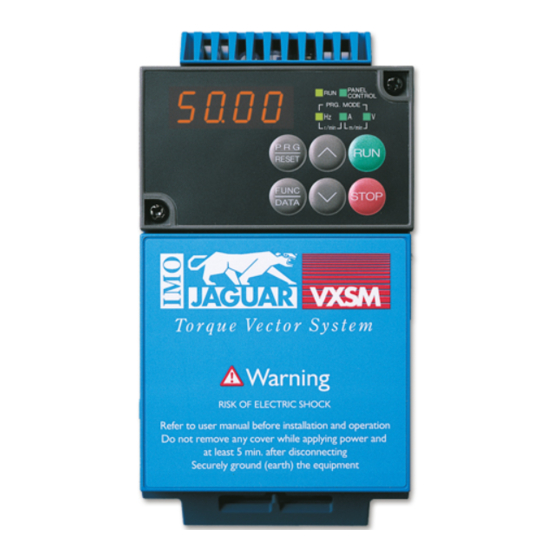
Instruction manual IMO Jaguar VXSM General Purpose Inver ter Single Phase 230V input, 0.4-2.2kW Three Phase 415V input, 0.4-7.5kW... -
Page 2: Table Of Contents
Contents Safety Instructions 6. Protective Operation 1. Before Using the Inverter 6-1 List of Protective Operations 1-1 Receiving Inspection 6-2 Alarm Reset 1-2 Appearance of Product 7. Troubleshooting 1-3 Handling the Product 7-1 When Protective Function 1-4 Transportation Activates 1-5 Storage 7-2 When Motor rotates Incorrectly 2. -
Page 4: Safety Instructions
Introduction Installation WARNING Safety precautions • Install inverter Read through this manual before starting nonflammable material such as metal. installation, connection (wiring), operation, or Otherwise fire could occur. maintenance and inspection for correct use. Be familiar with the knowledge about the device, •... - Page 5 • Both screws of grounding terminals of (Design the machine so that human safety is VXSM75-1/550-3 need to be tightened up ensured after restarting.) securely even if one grounding terminal is Otherwise an accident could occur.
-
Page 6: General Precautions
Maintenance and inspection and parts replacement WARNING • Turn the power off and wait for at least five minutes before starting inspection. (Further, check that the charge lamp is unlit, and check the DC voltage across the P (+) and N (-) terminals to be lower than 25Vdc.) Otherwise electric shock could occur. - Page 7 Conformity to Low Voltage Directive in EU [Available only for the products with CE or TÜV mark] 8. Install the inverter, AC or DC reactor, CAUTION input or output filter in an enclosure , to Safe separation for control prevent a human body from touching interface of this inverter is provided directly this equipment.
- Page 8 L1/L, L2/N L1/L, L2/N Control Control Breaker P1, P(+) section P1, P(+) section DB, N(-) DB, N(-) U,V,W U,V,W 14 (2.1) VXSM40-1 VXSM75-1 (0.5) VXSM150-1 12 (3.3) VXSM220-1 10 (5.3) VXSM40-3 VXSM75-3 VXSM150-3 14 (2.1) VXSM220-3 (0.5) VXSM400-3 VXSM550-3 12 (3.3) VXSM750-3 10 (5.3)
-
Page 9: Before Using The Inverter
1PH 200-240V 50/60Hz 6.4A Unpack and check the following items. If you have any problems with the product, 3PH 0.4kW 200-230V 0.2-400Hz 3.0A contact IMO Precision Controls Ltd. 150% 1min (1) Check the ratings nameplate to confirm that 010113R001 the delivered product is the ordered one. - Page 10 (1-2) Overall view (5.5,7.5kW) Keypad panel mounting screw Keypad panel Intermediate cover Ratings nameplate Terminal block cover (2-1) View of wiring part(4.0kW or below) Control cable port P1, P (+), DB, N (-) cable port L1/R, L2/S, L3/T (L1/L, L2/N), U, V, W cable port Grounding cable port A barrier is provided in the main circuit terminal...
-
Page 11: Handling The Product
(2-2) View of wiring part(5.5,7.5kW) Terminal block cover Control cable port L1/R, L2/S, L3/T cable port P1, P (+), DB, N (-) cable port U, V, W cable port Cable cover Grounding cable port A barrier is provided in the cable cover for the P1, P (+), DB and N (-) cable port. - Page 12 Removing the main circuit terminal block Removing terminal block cover(4.0kW or below) cover(5.5,7.5kW ) While lightly pushing the sides of the main Loose the screws indicated below and while circuit terminal block cover at the catches, slide lightly pushing the sides of the terminal block toward you in the procedure shown in Fig.
- Page 13 Removing the keypad panel Loosen the keypad panel mounting screws and remove the keypad panel in the procedure shown in Fig. 1-3-4. During the procedure, slowly remove the keypad panel right toward the top. If the keypad panel is handled abruptly, the connector will be broken.
-
Page 14: Transportation
Transportation To store for a long time Always hold the main unit when carrying the inverter. The long-term storage method of the inverter If covers or parts are held, the inverter may be varies largely according to the environment of broken or it may drop. -
Page 15: Installation And Connection
Installation and Above 100mm Connection Left Right Operating Environment 10mm 10mm VXSM Install the inverter in an environment described in Table 2-1-1. Item Specifications 100mm Below Site Indoors Ambient -10 to +50 degree C Fig. 2-2-1 temperature (3) The temperature of the heat sink rises to Relative 5 to 95% (without condensation) about 90 degrees C during operation of the... -
Page 16: Connection
Connection WARNING Remove the control terminal block cover to • Be sure to connect the grounding connect the control terminal block. Remove the cable before applying power. main circuit terminal block cover to connect the Otherwise electric shock or fire could main circuit terminal block. - Page 17 Enclosure *1) Supply a source voltage suitable for the rated voltage of the inverter. *2) Optional part. Use when necessary. *3) Peripheral equipment. Use when necessary. *4) To connect a DC reactor (DCR) for power factor correcting, remove the jumper between the P1 and P (+) terminals.
-
Page 18: Connection Of Main Circuit And Grounding Terminal
2-3-2 Connection of Main Circuit and Grounding Terminal Symbol Name of terminal Description L1/R,L2/S,L3/T Main circuit power input Connects a 3-phase power supply. L1/L,L2/N Main circuit power input Connects a 1-phase power supply. U,V,W Inverter output Connects a 3-phase induction motor. P1,P(+) For DC reactor Connects an optional DC reactor. -
Page 19: Terminals
(3) DC reactor connecting terminals (P1, P (+)) a. Use this terminal to connect a DC Inverter reactor (option). Remove the jumper connected factory before connecting the DC reactor. P(+) b. Do not remove the jumper if no DC reactor is used. Cut the barrier in the main circuit terminal block cover for the P1, P (+), DB and N (-) cable port when connecting... -
Page 20: Connection Of Control Terminals
2-3-3 Connection of Control Terminals control function terminals varies according to the function setting. Refer to the connection Table 2-3-2 shows the functions of the control method for the function. circuit terminals. The method of connecting Classifi- Terminal cation symbol Terminal name Description of function Potentiometer power... - Page 21 Classifi- Terminal cation symbol Terminal name Description of function Analog monitor The monitor signal for analog DC voltage (0 to +10 Vdc) is output. The signal description can be selected from the following. • Output frequency1 (before slip compensation) • Output frequency2 (after slip compensation) •...
- Page 22 (1) Analog input terminals (13, 12, C1, 11) (2) Digital input terminals (FWD, REV, X1 a. Because weak analog signals are through X5, P24) handled, these signals are especially a. Generally the digital input terminals susceptible to external noise effects. (FWD, REV, X1-5) are turned on or off in Route the wiring as short as possible relation to the P24 terminal.
-
Page 23: Terminal Layout
Main circuit terminal drawing P1 P(+) N(-) VXSM40-1 L1/L L2/N Screw size : M3.5 Tightening torque : 1.2N . m P1 P(+) N(-) VXSM75-1 L1/L L2/N Screw size : M4 Tightening torque : 1.8N . m VXSM40-3 P1 P(+) N(-) VXSM75-3... - Page 24 (1) Main circuit terminal block(Continued) Inverter type Main circuit terminal drawing L1/R L2/S L3/T DB P1 P(+) N(-) VXSM550-3 VXSM750-3 Screw size : M5 Tightening torque : 3.5N . m (2) Control terminal block 30A 30B Y1E C1 30C Y2E CMC 11 CM FWD REV CM P24 Screw size: M2.5 Tightening torque: 0.4N◊m...
-
Page 25: Applicable Devices And Cable Sizes For Main Circuit
(ELCB) * [L1/L, L2/N] [U, V, W] [P1] wiring [kW] Rated current [A] [P(+)] With Without With Without reactor* reactor* VXSM40-1 VXSM75-1 0.75 VXSM150-1 VXSM220-1 (DB) (Others) VXSM40-3 VXSM75-3 0.75 VXSM150-3 VXSM220-3 VXSM400-3 VXSM550-3 VXSM750-3 Table 2-3-4 Selection of peripheral devices... -
Page 26: Operation
3. Operation Inspection and Preparation Before Operation Check the following before starting operation. (1) Check if connection is correct. Especially check if the power cables are connected to inverter output terminals U, V and W and that the grounding cable is grounded without fail. -
Page 27: Keypad Panel
➀ Digital display 4. Keypad Panel Various function codes and data codes for The keypad panel is provided with various programming are shown. functions such as operation (frequency setting The output frequency, output current and and start/stop commands) from the keypad other data are displayed during operation, panel, monitor and alteration of function code and the cause of a trouble is displayed... - Page 28 (2) Stopping operation (3) Changing the frequency When is other than When is at , press press to start operation or press key to increase the frequency or STOP to stop operation. The direction of press the key to decrease the rotation is as shown below.
-
Page 29: Upon An Alarm
(5) Changing the function code 4-1-2 Digital Frequency Setting Method The function code consists of an alphabetic Press the key at the operation character and a numeral. The alphabetic mode screen. The LED display changes character is defined for each of the function to the frequency setting, and the data groups. -
Page 30: Method
5. Selecting Functions Function Selection List Table 5-1-1 Function selection list F: Fundamental functions Min. Factory Name Setting range unit setting Data protection 0: Data change enabled 1: Data protected Frequency 0: Keypad operation command 1 1: Voltage input (terminal 12) 2: Current input (terminal C1) 3: Voltage and current input 4: Voltage input with polarity (terminal 12) - Page 31 Min. Factory Name Setting range unit setting Electronic thermal 0: Inactive overload relay 1: Active (for external braking resistor (for braking resistor) DB__-2C/4C) 2: Active (for external braking resistor TK80W : 0.1 to 2.2E11S-7 DB__-4C : 0.4 to 7.5E11S-4) Restart mode 0:Inactive (The inverter immediately after momentary trips upon power failure.)
- Page 32 Min. Factory Name Setting range unit setting FMA and FMP 0: Analog output (FMA) terminals 1: Pulse output (FMP)1 (Select) (Voltage adjust) 0 to 200% (Function) 0:Output frequency 1 (before slip compensation) 1:Output frequency 2 (after slip compensation) 2:Output current 3:Output voltage 4:Output torque 5:Load factor...
- Page 33 E: Extension terminal functions Min. Factory Name Setting range unit setting X1 terminal function 0: Multistep frequency selection [SS1] 1: Multistep frequency selection [SS2] 2: Multistep frequency selection [SS4] 3: Multistep frequency selection [SS8] X2 terminal function 4:Acceleration/deceleration time selection [RT1] 5: 3-wire operation stop command [HLD] 6: Coast-to-stop command [BX] 7: Alarm reset [RST]...
- Page 34 C: Control functions of frequency Min. Factory Name Setting range unit setting Jump frequency (Jump freq. 1) 0 to 400Hz (Jump freq. 2) (Jump freq. 3) (Hysteresis) 0 to 30Hz Multistep frequency setting (Freq. 1) 0.00 to 400.0Hz 0.01Hz 0.00 (Freq.
- Page 35 P: Motor parameters Min. Factory Name Setting range unit setting Number of motor 1 2 to 14 poles Motor1 (Capacity) 0.01 to 5.5kW (4.0kW or less) Nominal 0.01 to 11.00kW(5.5/7.5kW) 0.01kW applied motor kW (Rated current) 0.00 to 99.9A 0.01A standard rating _ Tuning)
- Page 36 H: High performance functions Min. Factory Name Setting range unit setting Total operation time Monitor only Trip history Monitor only ---- Data initializing 0: Manual set value (Data reset) 1: Return to factory set value Auto-reset (Times) 0: Inactive 1 to 10 times 1 time (Reset interval) 2 to 20s...
- Page 37 Min. Factory Name Setting range unit setting Serial link Monitor, Frequency , Operation (Function select) setting command RS485 1 to 31 (Address) (Mode select on 0: Immediate Er8 no response error) 1: Er8 after interval set by timer 2: Retry in interval set by timer (Er8 after failure to restore) 3: Continuation of operation (Timer)
- Page 38 A: Alternative motor parameters Min. Factory Name Setting range unit setting Maximum frequency 2 50 to 400Hz Base frequency 2 25 to 400Hz Rated voltage 2 0V, 80 to 240V(200V class) (at base frequency 2) 0V,160 to 480V(400V class) Maximum voltage 2 80 to 240V (200V class) (at maximum 160 to 480V(400V class)
- Page 39 O: Optional functions Min. Factory Name Setting range unit setting Optional 0: Option inactive selection 1: Option active Set 0 when optional card is not used Description of change during operation : Press the key to change the data. : The data changed by the key takes The new data takes effect after the key is...
-
Page 40: Detail Description Of Each
Detail Description of Each Normal mode operaton (setting: 1.3,4 Function F: Fundamental functions Inverse mode operaton (setting: 5 Data protection • The setting data can be protected against inadvertent operation at the keypad panel. 0: Data change enabled 1: Data protected [Setting method] 0¡1: Press the keys simultaneously. - Page 41 Frequency setting block diagram 5-12 Selecting Functions...
- Page 42 Maximum frequency 1 Acceleration time 1 • This is the maximum frequency which is Deceleration time 1 output by the inverter of motor 1. Setting range: 50 to 400 Hz • These are the acceleration time taken for the If a value larger than the rating of the driven output frequency to reach the maximum unit is set, the motor or machine may be frequency from the start, and the deceleration...
-
Page 43: (F Functions)
Torque boost 1 Electronic thermal overload relay 1 (Level) • This function is for motor 1. The following options can be selected. Electronic thermal overload relay 1 Selection of load characteristics such as (Thermal time constant) automatic torque boost, square reduction The electronic thermal overload relay watches the torque load, proportional torque load and output frequency, output current and operation... - Page 44 When the pickup function is used, the speed of 0: Inactive the coasting motor is detected and the motor is 1: Active - (For details contact IMO) started without a shock. Because a speed 2:Active - (For details contact IMO)
- Page 45 Note: The chain line indicates the motor speed. 5-16 Selecting Functions...
- Page 46 1% of the rated inverter output current. Setting range: 0 to 100% Actual minimum level is fixed to 5% even if this function set from 1 to 5% for VXSM75-1/550-3. • Braking time: Set the operation time of DC CAUTION braking.
- Page 47 Starting frequency (Frequency) Carrier frequency Lower Higher Motor noise Larger Smaller Starting frequency (Holding time) Output current waveform Worse Better Stop frequency Leakage current Less More RF emissions Less More • The starting frequency can be set to insure the torque during start of operation. Holding *A smaller setting causes a less sinusoidal time for at the starting frequency before output current waveform (with much harmonic...
- Page 48 Approx 15.6 [V] • Select the monitoring item to be output at the FM terminal. Pulse period Target of Definition of 100% of monitoring monitoring amount Pulse period [p/s] = 1/T Duty [%] = T1/T X 100 Output frequency 1 Maximum output Average voltage [V] = 15.6 X T1/T (before slip...
- Page 49 Slip compensation is automatically activated. Torque limiter 1 (Driving) When "0" is set, the slip compensation amount of a standard three-phase motor is Torque limiter 1 (Braking) assumed. When the setting is other than "0", • The torque limiting operation calculates the the written setting is applied.
-
Page 50: Extension Terminal Functions
Multistep frequency selection E:Extension Terminal Functions Combination of input Selected frequency X1 terminal function signals [SS8] [SS4] [SS2] [SS1] X2 terminal function Selected by F01 or C30 C05 Multistep frequency 1 X3 terminal function C06 Multistep frequency 2 C07 Multistep frequency 3 X4 terminal function C08 Multistep frequency 4 C09 Multistep frequency 5... - Page 51 Coast-to-stop command [BX] DC brake command [DCBRK] When the BX terminal is connected to the P24 When the external digital input signal is ON, DC terminal, the inverter output is immediately shut braking starts and continues as far as the signal off and the motor coasts to stop.
-
Page 52: (E Functions)
PID control cancel [Hz/PID] Torque limiter 2 (Driving) An external digital input signal can disable PID control. Torque limiter 2 (Braking) Input signal Selected function • Use these functions to switch the torque 16[Hz/PID] limiter levels set at F40 and F41 using an PID control valid external control signal. - Page 53 Torque polarity [B/D] Frequency level detection delay The polarity of the torque calculated inside the inverter is judged and the driving/braking torque FAR function signal (Hysteresis) discrimination signal is output. • Adjust the hysteresis and signal output delay When the calculated torque is positive/driving, for achievement of the output frequency to an OFF signal is output, and when it is the set frequency (operation frequency).
- Page 54 OL function signal (Mode select) Display coefficient A • The OL function signal includes two Display coefficient B variations: "overload forecast by means of the • function of the electronic thermal overload these functions conversion relay" and "overload forecast by means of coefficients for determining the display value output current".
-
Page 55: Control Functions Of Frequency
Multistep frequency 1 through C: Control Functions of Frequency Multistep frequency 15 C01 Jump frequency 1 • Terminal functions SS1, SS2, SS4 and SS8 are turned on or off to switch multistep C02 Jump frequency 2 frequencies 1 through 15. (Refer to E01 through E05 for the definition of the terminal C03 Jump frequency 3 function.) - Page 56 Timer operation Stage 1 • An operation pattern from the start of operation to automatic stop can be created. • Select active or inactive timer operation. 0: Inactive timer operation 1: Active timer operation • Set the time from the start of operation to automatic stop.
- Page 57 Setting State of operation P: Motor parameters Inactive The primary resistance (%R1) of the Number of motor 1 poles motor and the leakage reactance (%X) at the base frequency are measured • This parameter is the number of poles of while the motor is stopped, and the data driven motor 1.
- Page 58 function code (P05) is displayed. When the • Calculate %X in the following formula. FWD or REV terminal is connected to start tuning, disconnect the terminal. Note) Turn the BX and RST terminals off before starting tuning. where X1: Primary leakage reactance of motor [ohm] WARNING X2: Secondary leakage reactance of motor •...
-
Page 59: High Performance Functions
initialization completed, setting H: High Performance Functions automatically returns to "0". Auto-reset (Times) Total operation time Auto-reset (Reset interval) • The total power-on time of the inverter is displayed. When the protective function of the inverter A number between 0 and 6500 is displayed, which starts the retry function is activated, indicating 0 to 65000 hours. - Page 60 I Upon success of retry [S-curve acceleration/deceleration] To reduce the shock of the mechanical system, the change in the output frequency is made smooth when the frequency is set. α α β β β β I Upon failure of retry <Constant of each pattern>...
- Page 61 Start mode (Rotating motor pickup) Dec mode • • This function smoothly starts a motor Select the stopping method of the inverter coasting due to an external force or the like after a stop command. after momentary power failure. Setting 0: Normal The speed of the motor is detected upon (Deceleration to stop based on data power recovery or restart and the same...
- Page 62 restart is made after completion of operation • Because forward and reverse operation can preparation of the inverter (about 0.2 to 0.5 s). be selected for the output of the PID controller, the rpm of the motor can be Auto-restart(Frequency fall rate) increased or decreased in relation to the •...
- Page 63 Note) The feedback value of the PID control PID control (Feedback signal) can be input only in the positive polarity. • Select the feedback value input terminal and The negative polarity (0 to -10 Vdc, -10 electrical specification of the terminal. Select to 0 Vdc, etc.) cannot be input.
- Page 64 time, vibration may become larger. With a PID control (I (integral time)) small differential time, decrease in the • I action deviation becomes smaller. An operation where the speed of the change in the amount of operation is proportional to •...
- Page 65 (operation level) of terminal [C1] is calculated in PTC thermistor (Mode select) the following equation. • Select this function for a motor equipped with a PTC thermistor for overheat protection. Setting 0: Inactive 1: Active Connect the PTC thermistor as shown in the figure.
- Page 66 1) Monitoring (monitoring of various data, RS485 (Timer) confirmation of function code data) • Set the error handling timer value. 2) Frequency setting Setting range: 0.0 to 60. 0 s 3) Operation command (FWD, REV and other commands set for digital input) RS485 (Baud rate) 4) Function code data writing •...
- Page 67 Maximum temperature of heat sink A: Alternative motor parameters • The maximum value in each hour is displayed in degree C. Maximum frequency 2 Maximum effective current The maximum frequency output by the inverter for motor 2. This parameter functions in the •...
- Page 68 of motor 2 poles Motor (Slip compensation response time 2) The number of poles of driven motor 2. This parameter functions in the same way as P01 Set the response time for slip compensation of "Number of motor 1 poles". For the description, motor 2.
-
Page 69: List Of Protective Operations
Protective Operation List of Protective Operations When an error occurs to the inverter, a protective function is activated to trip the inverter immediately, displaying the name of the alarm at the LED and allowing the motor to coast to stop. Name of alarm Display Description of operation... -
Page 70: Alarm Reset
Alarm Reset When the inverter trips, remove the cause then press the PRG/RESET key on the keypad panel or input a reset command from the RST control terminal to reset the tripping state. Because the reset command is activated by an edge, supply the command in an OFF - ON - OFF sequence as shown in Fig. -
Page 71: Troubleshooting
Troubleshooting When Protective Function Activates Overcurrent Troubleshooting... - Page 72 Overvoltage Undervoltage Troubleshooting...
- Page 73 Inverter inside overheat or heat sink Eternal alarm input overheat Inverter overload, motor overload Troubleshooting...
- Page 74 Memory error Er1, keypad panel Output wiring error communication error Er2, CPU error Er3 (9) Input phase loss Troubleshooting...
-
Page 75: When Motor Rotates Incorrectly
When Motor rotates Incorrectly The motor does not rotate. The motor does not start when a coast-to-stop command or DC braking command is being input. Troubleshooting... - Page 76 The motor rotates but the speed does not change. The change in the rotation speed of the motor is also small in the following cases. — "F01 "Frequency command 1" and C30 "Frequency command 2" are set at "3" and a signal is input from both of control terminals 12 and C1, and there is no change in the sum of them.
- Page 77 The motor loses speed during acceleration. Excessive heat generation from motor Troubleshooting...
-
Page 78: Maintenance And Inspection
Maintenance and Periodic Inspection Inspection After stopping the operation, turn the power off and remove the front cover to perform periodic Perform daily and periodic inspection to avoid inspection. problems and ensure reliable operation for a The smoothing capacitor at the DC section of long time. - Page 79 Common 1) Check if bolts and screws are tight 1) Retighten 1), 2), 3) and not missing. 2), 3) Visual No abnormalities 2) Check the devices and insulators for inspection deformation, cracks, breakage and discoloration caused by overheat and deterioration. 3) Check for dust.
- Page 80 • Judgment of life using maintenance data (2)Life of cooling fan The maintenance data of function codes H42 Function code H43 indicates the total and H43 can be used to display data for the operation time of the cooling fan. The time is judgment of the capacitance of the capacitor in integrated in units of an hour and fractions the main circuit and the life of the cooling fan to...
-
Page 81: Measurement Of Current And Voltage In Main Circuit
Measurement of Current and current on each of the input and output sides and calculate in the following formula. Voltage in Main Circuit Because the voltage and current of the power supply (input) of the main circuit of the inverter In case of Three-phase and the output (motor) include harmonic components,... -
Page 82: Insulation Test
When the withstand Cooling fan 3 years Replace with voltage test is necessary, contact IMO. a new part. (1) Megger test of main circuit 1) Use a 500 VDC Megger and shut off the Smoothing... -
Page 83: Specifications
Specifications Standard Specifications Single-phase 200V input Item Detail specifications Inverter type VXSM 40-1 75-1 150-1 220-1 Nominal applied motor * [kW] 0.75 Rated capacity * [kVA] Rated voltage * Three-phase 200V / 50 Hz, 200V, 220V, 230V / 60 Hz (with AVR function) Rated current * (2.5) (4.0) - Page 84 Three-phase 400V input Item Detail specifications Inverter type VXSM 40-3 75-3 150-3 220-3 400-3 550-3 750-3 Nominal applied motor * [kW] 0.75 Rated capacity * [kVA] Rated voltage * Three-phase 380,400,415V/50Hz, 380,400,440,460V/60Hz (with AVR function) Rated current * (1.4) (2.1) (3.7) (5.3) (8.7)
-
Page 85: Common Specifications
Common Specifications Item Detail specifications Maximum 50 to 400 Hz variable frequency Base 25 to 400 Hz variable frequency Starting frequency 0.1 to 60.0 Hz variable, Holding time : 0.0 to 10.0s. Carrier 0.75 to 15 kHz (The carrier frequency may automatically drop to 0.75 kHz to frequency protect the inverter. - Page 86 Item Detail specifications Frequency Keypad operation: key and key. setting Setting with potentiometer (external potentiometer: 1 to 5 kΩ 1/2 W) Setting with 0 to ± 5 Vdc. Setting with 0 to ± 10 Vdc. Setting with 4 to 20 mAdc. 0 to +10 Vdc / 0 to 100% can be switched to +10 to 0 Vdc / 0 to 100% externally.
- Page 87 Item Detail specifications PID control This function can control flowrate, pressure, etc. with analog feedback signal| The reference and feedback values are displayed in %. Reference signal Keypad operation key and key.: 0.0 to 100% Voltage input (Terminal 12) : 0 to 10Vdc Current input (Terminal C1) : 4 to 20mAdc Multistep frequency setting...
- Page 88 Item Detail specifications Overload Inverter protection electronic thermal overload relay protection Overvoltage An excess in the DC link circuit voltage (approx. 400 Vdc for 200V class, approx. protection 800Vdc for 400V class) is detected for inverter protection. Overcurrent The inverter is protected against an overcurrent caused by an overload on the protection output side.
-
Page 89: External Dimensions
External Dimensions Type Standard External dimensions (mm) applicable motor [kW] VXSM40-1 Specifications... - Page 90 Installation screw size : M4 (4 pcs) Type Standard External dimensions (mm) applicable motor [kW] VXSM 75-1 0.75 62.5 VXSM 40-3 50.5 VXSM 75-3 0.75 62.5 VXSM 150-3 86.5 VXSM 220-3 86.5 Specifications...
- Page 91 Type Standard External dimensions (mm) applicable motor [kW] VXSM 150-1 94.5 VXSM 220-1 94.5 VXSM 400-3 94.5 Specifications...
- Page 92 Installation screw :size : M5 (4pcs) VXSM550-3 VXSM750-3 34.32 4.75 60.5 4.75 12.5 21.82 RJ45 Connector P R G RESET FUNC STOP DATA RJ45 Connector 2-ø3.2 Clearance hole for RJ45 Counter bore ø6.6, depth 4 Connector to be o26 Top view Front view Side view VXSM Keypad...
-
Page 93: Rs485 Communication
RS485 Communication Remove the keypad panel of the inverter referring to section 1-3 (3) and use the connector having been connected with the keypad panel to connect up to 31 inverters in a line to perform the following operations. • Frequency setting, forward/reverse rotation, stop, coast to stop, alarm reset and other operations •... -
Page 94: Connector And Communication Cable
Model : IDACS-1520 terminals of the inverter main body is changed Manufacture : IMO Precision Controls Ltd to be the LE terminal which is used for remote/local switching. Any of the functions E01 through E05 is used to change the function of 9-4-3 Remote/local changeover X1 to X5 terminal. -
Page 95: Communication Protocol
9-4-4 Communication Protocol Serial communication specification Physical level Compliance with EIA RS-485 (2-wire type) Number of connected Host x 1 unit, inverter x 31 units (Station address 1 to 31) stations Transmission speed 19200, 9600, 4800, 2400, 1200[bit/s] Synchronization method Start-stop Transmission method Half duplex... - Page 96 Transmission procedure before timeout, normal reception may become impossible, so that timeout should be judged 1) Set communication functions H30 through correctly. The timeout time is one second in the H39. selecting mode and 0.5 second in the polling 2) Make communication according mode.
-
Page 97: Standard Frame
9-4-5 Standard Frame transmission speed can be increased. Note: Numbers with "H" at the end indicate The ASCII code character method is employed. hexadecimals. A standard frame has a fixed length of 16 bytes. Using optional frames (12 bytes or 8 bytes), the Host¡Inverter frame 7(6) Fixed to 01H. -
Page 98: Short Frame
9-4-6 Short Frame Short frames are prepared for special functions to reduce the data transmission time. Selecting Host¡Inverter (selecting) 7(6) Fixed to 01H. Start-of-heading character (SOH) Designate a station address of the destination Tens digit of station address (ASCII) inverter with 01 to 31 or 99. (designation of each Units digit of station address (ASCII) character in ASCII) Fixed to 05H. -
Page 99: Details Of Frame
Polling Host¡Inverter (polling) 7(6) Fixed to 01H. Start-of-heading character (SOH) Designate the station address of the destination Tens digit of station address (ASCII) inverter with 01 to 31 or 99. (designation of each Units digit of station address (ASCII) character in ASCII) Fixed to 05H. -
Page 100: Broadcasting
characters. Refer to section 9-4-11 Function Code List for details. (7) Special additional data This is normally a space (20H). In a response frame issued by an inverter to request for frequency monitor (M09), a minus sign is set in ASCII during reverse rotation output. -
Page 101: Communication Error Code
9-4-9 Communication Error Code The inverter detects the following errors. The error code is in hexadecimal notation. Error code Name of error Description (hexadecimal) Checksum error The checksum of the frame sent to the own station is in discrepancy. Parity error The parity is in discrepancy. -
Page 102: Function Code List
9-4-11 Function Code List The function code includes the function codes indicated in chapter 5 "Selecting Functions" and the following functions for the standard and short frames. (1)Functions for standard frame (command data) Name Command Function type Data and operation type character and number... - Page 103 (2)Functions for standard frame (monitor data) Name Command Function type Data and operation type character and character number Frequency ±20000d/fmax (Max. frequency) (Final value) Frequency 100=1.00Hz (Value multiplied by 100) command value The current frequency setting is returned. Calculated torque 100% (rated torque) / ±...
- Page 104 Name Command Function type Data and operation type character and character number Failure description; R current one Failure description; R previous one Failure description; R Refer to (4) Alarm display data one before previous one Failure description; R one before two previous ones Total operation 0 to 65535 / 0 to 65535 hours...
- Page 105 Functions for short frame Function Command Data direction Data range; transmission Change type data / actual data during character operation Frequency command Selecting Same as S01 Frequency command Selecting Same as S05 Operation command Selecting Same as S06 Reset command Selecting 4 spaces Calculated torque...
-
Page 106: Data Format
9-4-12 Data format The data format of each piece of function code data of the inverter is defined here. Prepare data according to the format numbered in the data format for each function code. (Refer to section 5-1 Function Setting List and section 9-4-11 Function Code List for the data format.) The data field of the transmission frame except for data format 10 consists of a 4-digit ASCII... - Page 107 Data format 6 Acceleration/deceleration time, amperage data 15 14 13 12 11 10 Index Data field Polarity Unused 0 : 0.01 001~999 (0.01~9.99) 1 : 0.1 100~999 (10.0~99.9) 2 : 1 100~999 (100~999) 3 : 10 100~360 (1000~3600) 0: Positive (+), 1: Negative (-) Example: In the case that F07: communication No.
- Page 108 Data format 9 General-purpose output terminal 15 14 13 12 11 10 0 X2 X1 Unused General-purpose input (All bits: "1" when turned on) Example: In the case that M15: (general-purpose output terminal) = 0000 0000 0000 0001 (bin.): Y1 = ON M15 = 0001 (hex.), hence: 0001 ➾...
- Page 109 (11) Data format 11 16-bit binary code, least increment 0.01, positive/negative data (5-byte ASCII code) ASCII code 4-digit hexadecimal data➾ 4-digit ASCII code (of minus sign Example: In the case that M09 (output frequency) = +60.00 Hz 60.00 ¥ 100 = 6000 (dec.) = 1770 (hex.), hence: ➾...
-
Page 110: Options
10. Options 10-1 External Options Molded case The molded case circuit breaker (MCCB) is connected for the protection of circuit breaker the main circuit wiring up to the inverter and for turning the power on and off. The rated current or the rated interrupting capacity varies according to the power supply specifications. -
Page 111: Applicable Reactor
11. Applicable Reactor The DC reactors are recommended to reduce inverter input harmonic current or to correct inverter input power factor. Applicable inverter model DC reactor (DCR) VXSM40-1 VXSM75-1 Contact IMO Precision VXSM150-1 Controls Limited VXSM220-1 VXSM40-3 VXLC40 VXSM40-3 VXLC75... -
Page 112: Electromagnetic Compatibility
VXSM550-3 RFM750-3 VXSM750-3 Table 12-2-1 RFI filters Note: The above data may be subject to change Note: without notice. If in doubt contact IMO Precision For details, refer to IMO Precision Controls Ltd. Controls Ltd, before specifying. Electromagnetic Compatibility 12-1... - Page 113 All rights reserved. No part of this publication may be produced or transmitted in any form or by any means, electronic or mechanical including photocopying, recording, or by any information storage or retrieval system without the written permission of IMO Precision Controls Ltd © IMO Precision Controls Ltd 2001...
- Page 114 IMO Precision Controls Limited Out-of-hours telephone contacts 1000 North Circular Road Product support Staples Corner, London NW2 7JP 07831 207220 Telephone: +44 (0)20 8452 6444 07831 207221 Fax: +44 (0)20 8452 3512 Web: www.imopc.com Email: imo@imopc.com...
Need help?
Do you have a question about the VXSM75-1 and is the answer not in the manual?
Questions and answers