Table of Contents
Advertisement
Quick Links
Advertisement
Chapters
Table of Contents

Related Manuals for ResMed Elisee 150


Summary of Contents for ResMed Elisee 150
- Page 1 Elisée ™ Clinical Manual English NOT013189-6 07 11...
- Page 3 Elisée ™ Clinical Manual English NOT013189-6 07 11...
- Page 4 ResMed Schweiz AG Viaduktstrasse, Basel, Switzerland, +41 61 564 7000. Saime SAS (Manufacturer), Z.I., 25 rue de l’Etain, 77176 Savigny-le-Temple, France. ResMed Corp Poway, CA, USA +1 858 746 2400, ResMed Ltd Bella Vista, NSW, Australia, +61 (2) 8884 1000. ResMed has offices in Austria, Brasil, China, Finland, France, Germany, Hong Kong, India, Japan, Malaysia, the Netherlands, New Zealand, Norway, Singapore, Spain, Sweden, Switzerland and the United Kingdom (see www.resmed.com for details).
- Page 5 Foreword Contents of the Manual This clinical manual is for an Elisée™ 150 ventilator with a software version of 2.3X or higher. The manual is divided into sections. A summary of the information contained in each section is given below: •...
-
Page 7: Table Of Contents
Contents Foreword ............iii 1 General Safety Instructions . - Page 8 5 Clinical Configuration and Use ........63 5.1 Accessing the clinical screens 5.2 Manual test 5.3 Programming ventilation options...
- Page 9 8 Maintenance and Disinfection ........127 8.1 Cleaning and maintenance frequency Cleaning frequency ..........................
- Page 10 viii...
-
Page 11: General Safety Instructions
1 General Safety Instructions The following are general safety instructions. Other specific warnings and notes can be found throughout the text of the manual. This manual must be read and understood in full by the user before the device is used by a patient. •... - Page 12 • There is a technical manual for the ventilator, which is issued at ResMed training sessions. It must be read and understood by the technicians responsible for servicing the ventilator.
-
Page 13: Introduction And Description
2 Introduction and Description 2.1 Purpose of the Elisée 150 The Elisée 150 is a valve ventilation device delivering both pressure and volumetric ventilation, making it suitable for ventilating adult or child patients, at home and/or in a hospital setting. It is not designed for neonatal ventilation and should not be used with circuits with a 10mm diameter. -
Page 14: Description Of The Ventilator's Exterior
2.2 Description of the ventilator’s exterior 1. Mains or external power supply LED (see "Power status information" on page 20). 2. Retractable handle. 3. Internal and external battery LEDs: indicate the battery charge levels. 4. Alarm Silence button. 5. Brightness sensor: automatically adjusts the screen contrast. 6. - Page 15 12. External DC power socket 12 - 28V / 15A max. 13. On/Off push button. 14. Serial link cable connection socket for connecting to a PC. 15. Remote alarm socket. Figure 2.4: View of right side. 16.Low-pressure O port connection. 17.
-
Page 16: Table 2.1: Description Of A Specimen Serial Number, E.g. El2D0701001
19. Manufacturer plate. 20. Ventilator serial number. Table 2.1: Description of a specimen serial number, e.g. EL2D0701001 EL2D Product Year of Month of manufacture Sequential manufacture number code manufacture 21. Compartment for mains power pack or external battery pack. 22. Speaker. 23. -
Page 17: Description Of Power Sources
2.3 Description of power sources The Elisée 150 can operate with four different power sources. The device automatically selects the most secure available power source according to the following order of priority: 1. Mains AC voltage: 100-230VAC / 50-60Hz / 0.6-1A (mains power pack inserted in the Elisée compartment). -
Page 18: External Dc Power Supply
External DC power supply External power supply cord (mains 12-28 VDC power cord power pack/Elisée connection) Figure 2.8: External DC power cords. An external DC power source (in a vehicule with 12-28V, 15A max.) can be used by connecting the external power cord to the right side of the ventilator (see "Figure 3.3: 12-28VDC power cord, connected."... -
Page 19: External Battery Pack
External battery pack Figure 2.9: Li-Ion external battery pack. This battery pack is attached and removed in the same way as the mains power pack (see "Mains power pack" on page 23). This power supply takes priority over the internal battery. Note: The external battery pack should be disconnected when the ventilator is switched off. -
Page 20: Power Status Information
Power status information There are three LEDs on the top of the device showing the status of the power sources. Table 2.2: Power status information Power source Symbol and LED status Meaning Mains or Green. Mains power pack or external DC external. -
Page 21: Description Of The Gas Supplies
2.4 Description of the gas supplies Air inlet for gas supply Oxygen port Figure 2.10: Gas supply. Air inlet Ambient air passes through a removable anti-dust filter before arriving in the pressurised air circuit. Caution Do not obstruct this filter. Oxygen port The Elisée 150 has a low-pressure oxygen port (maximum 400kPa and 15L/min). - Page 22 22/174 NOT013189-6...
-
Page 23: Installation
3 Installation 3.1 Power supplies Mains power pack Connections 1. Insert the two lugs on the mains power pack into their slots. 2. Push firmly on the mains power pack until the clip locks into place. 3. Connect the mains power cord to the power port on the side of the pack. -
Page 24: External Dc Power Supply
Note: The power pack is operational as soon as it is connected to the mains supply. This pack can also be used outside of its compartment, in which case it is connected to the ventilator using the external power cord. This arrangement enables the ventilator to operate on mains power and recharge the external battery at the same time. -
Page 25: External Battery Pack
External battery pack This battery pack is attached and removed in the same way as the mains power pack (see "Figure 3.1: Connecting the mains power cord to the mains power pack in its compartment." on page 23). This power supply takes priority over the internal battery. Note: The external battery pack should be disconnected when the ventilator is switched off. -
Page 26: Gas Supply Air Inlet
3.2 Gas supply Air inlet Position the Elisée 150 so that air flow is not impeded. Note: Do not block the air vents. Low-pressure oxygen 1. Press on the side of the low-pressure O port connection to insert the metal connector. 2. - Page 27 Turning the oxygen monitoring on and off Turning the oxygen monitoring on 1. Turn off the ventilator (see "Turning off" on page 36). 2. Fit the oxygen sensor into its compartment (see "Replacing the O2 cell" on page 131). 3. Turn on the ventilator (see "Turning on" on page 35) and perform a manual test (see "Manual test"...
-
Page 28: Patient Circuits And Accessories
3.3 Patient circuits and accessories The Elisée 150 can be used with a single limb or a double limb patient circuit owing to its interchangeable expiratory valve control system. To obtain the best results from this ventilation system, a humidification system and/or antibacterial filters may be added. The Elisée 150 ventilator is suitable for both adults and children. -
Page 29: Connection Of The Single Limb Circuit And Double Limb Circuit Expiratory Supports
Connection of the single limb circuit and double limb circuit expiratory supports There are two supports available: • The single limb circuit support, to which the expiratory valve control and the proximal pressure line can be connected. Figure 3.6: Single limb circuit support. •... -
Page 30: Connecting A Single Limb Patient Circuit
Connecting a single limb patient circuit For correct operation, we recommend the use of a CIR011563 single limb circuit or equivalent. Figure 3.9: Single limb patient circuit. 1. Check that the Elisée 150 is fitted with a single limb circuit support (if not, replace it, see "Connection of the single limb circuit and double limb circuit expiratory supports"... -
Page 31: Connecting A Double Limb Patient Circuit
Connecting a double limb patient circuit For correct operation, we recommend the use of a CIR009727 double limb circuit or equivalent. Figure 3.11: Connecting a double limb circuit. Check that the Elisée 150 is fitted with a double limb circuit support (if not, replace it, see "Connection of the single limb circuit and double limb circuit expiratory supports"... -
Page 32: Connecting Accessories
Connecting accessories Note: Remember to perform a manual test after every change made to the patient circuit. Antibacterial filter Figure 3.12: Connecting an antibacterial filter. The Elisée 150 can be fitted with an antibacterial filter or a heat and moisture exchange (HME) filter. - Page 33 Remote control Figure 3.14: Connecting a remote control. A remote control is available for the Elisée 150 which can be used to start and stop ventilation and to silence audible alarms (those that can be permanently or temporarily turned off). The remote control connects to the serial port connection socket.
- Page 34 Trolley The Elisée 150 can be attached to a trolley. First, use an Allen key to fit a multi-support adapter to the Elisée, as shown below: Figure 3.15: Fitting a multi-support adapter. Then attach the Elisée 150 and multi-support adapter to the trolley, using the trolley's retaining slot.
-
Page 35: Turning The Elisée 150 On And Off Turning On
3.4 Turning the Elisée 150 on and off Turning on Press the button on the right side of the ventilator. Figure 3.17: Turning the ventilator on. Using the touch screen Press directly on the appropriate screen icons to access display screens and select parameters. Wednesday February 11: 28: 31... -
Page 36: Turning Off
Turning off Press the button on the right side of the ventilator. If the ventilator is in the patient screens and not delivering ventilation, the following screen appears. Back Do you want to switch off? Figure 3.19: "Do you want to switch off?" screen. The question "Do you want to switch off?"... - Page 37 If the ventilator is in the patient screens and delivering ventilation, the following screen appears. Back Pause (stop ventilation) < PS Stop machine < PE Figure 3.21: “Turning off the ventilator in patient mode during ventilation” screen (as Fig 3.19). If the ventilator is in the clinical screens and delivering ventilation, the following screen appears.
- Page 38 38/174 NOT013189-6...
-
Page 39: Ventilation
4 Ventilation 4.1 Ventilation parameter definitions Pressure support (cmH The pressure supplied by the device in addition to the PEEP during inspiratory phases in PS.SV (PS) and PS.VT modes. PEEP Figure 4.1: Pressure support. Recruitment cycles Recruitment cycles open collapsed alveoli by maintaining a longer insufflation time during a controlled pressure cycle. - Page 40 The device imposes respiratory cycles on the patient with the following adjustable parameters: • the recruitment period (the interval between two recruitment cycles); • the recruitment size (duration of insufflation in the recruitment cycle); • the recruitment pressure (pressure insufflated during the recruitment cycle). Max.
- Page 41 With a constant flow (1), the delivered flow is more or less constant throughout the active inspiratory phase. With a decreasing flow, the delivered flow decreases throughout the active inspiratory phase. Four settings are available with I/E or Ti: • flow with a decreasing slope setting of 2;...
- Page 42 Respiratory rate (bpm) The number of breaths per minute. The respiratory rate can be controlled by the device (controlled breaths) or by patients themselves with the support of triggers (spontaneous or assisted controlled breaths). Backup respiratory rate (bpm) Fmini The minimum respiratory rate. The backup rate ensures the patient takes a minimum number of breaths per minute.
- Page 43 Inspiration to expiration ratio The ratio of inspiration time to expiration time for each breath. P Insp. Example: Ti = 2seconds Te = 4seconds I/E = 1/2 Figure 4.11: I/E ratio. Apnea time Tapnea (s) Period of time after which the device delivers a respiratory cycle if the patient has not breathed. This parameter is available in spontaneous mode only (see "Spontaneous ventilation (PS.SV (PS) and PS.VT)"...
-
Page 44: Table 4.1: Ti Max Setting Guide
Maximum inspiratory time Ti Max (s) The maximum time for which the device will maintain inspiratory pressure before cycling to expiration. It gives the patient a window of inspiratory time in which to spontaneously cycle into the expiratory phase. Ti Max is available in spontaneous mode only (see "Spontaneous ventilation (PS.SV (PS) and PS.VT)"... - Page 45 Expiratory trigger Tg Exp The value which defines the end of an inspiratory phase. It can be expressed in two ways: • In automatic mode: Automatic cycling allows the inspiratory time to be adapted to the flow shape, and particularly to the max. An imaginary line (the dotted line in the diagram) is drawn from the point where the cycle began to the point with the coordinates '3seconds;...
- Page 46 Inspiratory trigger The value which defines when an inspiratory phase is triggered. This trigger can be defined in terms of flow or of pressure: • Invasive inspiratory flow trigger TgI( ): Operates with a double limb circuit only. At the end of expiration, when the patient starts to inhale, the flow measured by the expiratory sensor becomes lower than the flow measured by inspiratory sensor.
- Page 47 Tidal volume (mL) The volume of air received by the patient from the device (V ), and the volume of air exhaled by the patient (V Figure 4.17: Tidal volume (V Backup tidal volume (mL) This is the minimum tidal volume delivered in each cycle. However, this volume cannot be delivered in the following situations: •...
-
Page 48: Ventilation Modes (Assisted) Controlled Ventilation ((A)Cv And P(A)Cv)
4.2 Ventilation modes (Assisted) Controlled Ventilation ((A)CV and P(A)CV) In (Assisted) Controlled Ventilation, the device delivers cycles with a fixed insufflation time and set volume ((A)CV mode) or set pressure (P(A)CV mode). In CV and PCV modes, cycles are triggered by the device (set respiratory rate). In ACV and PACV modes, cycles can also be triggered by the patient (flow or pressure trigger) if the patient's respiratory rate is higher than the set respiratory rate. - Page 49 Note: During (A)CV, the Elisée 150 delivers flow-controlled cycles. Airway pressure and alveolar pressure then depend on the resistance and compliance of the patient’s respiratory system. It is important to set the high-pressure alarm (Pmax) to avoid the risk of barotrauma. The bar graph, shown on all ventilation screens, allows you to monitor airway pressure.
-
Page 50: Table 4.3: Adjustable Parameters In P(A)Cv Mode
P(A)CV Principle of (Assisted) Controlled Pressure Ventilation The course of a cycle In P(A)CV mode, cycles are pressure controlled. Flow is adjusted to maintain the set pressure during the set inspiratory time. Controlled cycles are delivered according to the respiratory rate set by the user. - Page 51 Set P Fixed Ti Fixed Ti T mecha T mecha T mecha T mecha T insp T insp patient effort T mecha: Device period (depends on frequency) CC: Controlled Cycle ACC: Assisted Controlled Cycle Figure 4.20: PACV mode - Assisted Controlled Pressure Ventilation. Set P Fixed Fixed...
-
Page 52: Intermittent Assisted Controlled Ventilation (Synchronised Intermittent Mandatory Ventilation) Simv And Psimv
Intermittent Assisted Controlled Ventilation (Synchronised Intermittent Mandatory Ventilation) SIMV and PSIMV In the Intermittent Assisted Controlled Ventilation modes, the device alternates between cycles of assisted controlled ventilation (with regulated flow (SIMV) or regulated pressure (PSIMV)) and spontaneous cycles with pressure support (PS) triggered by the patient. This mode allows spontaneous breathing. - Page 53 Patient triggering of Device controlled Triggering of a Support an assisted controlled cycle cycle cycle by the patient Zone 2 Zone 3 Zone 1 T exp ΔT ΔT T mecha T mecha T mecha T mecha Wvs: Window for the triggering of spontaneous PS cycles Wsync: Window for the triggering of assisted controlled cycles (5 or 1.5 s) T mecha: Device period defined by the frequency Figure 4.22: Operation of SIMV mode.
-
Page 54: Table 4.4: Adjustable Parameters In Simv Mode
Note: • During SIMV it is important that you monitor the level of pressure in the patient's airway through the high pressure alarm, to avoid barotrauma. • During PSIMV, for both assisted controlled cycles and spontaneous cycles with pressure support, the tidal volume is not set but results from the set pressure gradient and from the patient's respiratory mechanics. - Page 55 Pressure Synchronized Intermittent Mandatory Adjustable parameters Ventilation PSIMV Slope Inspiratory triggers Expiratory trigger Apnea parameters Recruitment parameters Ventilation 55/170 NOT013189-6...
-
Page 56: Spontaneous Ventilation (Ps.sv (Ps) And Ps.vt)
Spontaneous ventilation (PS.SV (PS) and PS.VT) The Elisée 150 offers two modes of spontaneous ventilation: pressure support with backup volume and pressure support with minimum volume. Both modes include apnea ventilation as backup ventilation for the patient. PS.SV (PS) Principle of Pressure support Pressure support is a pressure mode which supports the patient's spontaneous respiration. - Page 57 PS max = PS + PEEP + 5 hPa +20% (PS + PEEP) PS + PS max/2 PEEP PEEP < V < V Figure 4.24: Mode PS.SV (PS), pressure increased to reach V Expiratory phase The device cycles into the expiratory phase: •...
-
Page 58: Table 4.6: Adjustable Parameters For Ps
Table 4.6: Adjustable parameters for PS Adjustable parameters Pressure support with backup tidal volume PS.SV (PS) Flow shape Fmini Ti, max flow or I/E Ti Max P insp. PEEP Slope Inspiratory trigger Expiratory trigger Apnea parameters Recruitment parameters 58/170 NOT013189-6... - Page 59 PS.VT Principle of pressure support with minimum tidal volume Inspiratory phase The start of each cycle is triggered by the patient. However, the Elisée 150 has a backup rate setting (Fmini): if the number of cycles triggered by the patient is less than the backup rate, support cycles will be triggered by the device.
- Page 60 Timax Figure 4.27: PS.VT curve - Minimum tidal volume delivered with switch to volumetric mode. Based on its analysis of the fixed pressure support and Ti Max parameters, the device detects, during the course of the cycle, that the target minimum tidal volume V cannot be delivered.
- Page 61 Reaching the minimum tidal volume (V inst (inst) Ti max Ti(inst) = Time since the start of inspiration Vadm = Tidal volume already administrated (Air flow integrated during Ti(inst)) Figure 4.28: Minimum tidal volume (V ) calculation in PS.VT mode. At any given moment: Ti Max - Ti(inst) = Trem where...
-
Page 62: Table 4.7: Adjustable Parameters In Ps.vt Mode
mode: being unable to deliver a minimum V in each cycle when the patient's inspiratory effort is reduced, the patient's compliance is altered and/or the patient's resistance is increased. Table 4.7: Adjustable parameters in PS.VT mode Adjustable parameters Pressure support with backup tidal volume PS.VT Flow shape Fmini Ti, max flow or I/E... -
Page 63: Clinical Configuration And Use
5 Clinical Configuration and Use 5.1 Accessing the clinical screens Warning Only physicians and competent nursing and technical staff are permitted to access the clinical screens. The patient must never be told how to access these screens. Monday 18 18 June Monday June Last test the 18/06/07... - Page 64 As soon as the clinical mode is accessed, the program selection screen appears. Last test the 18/06/07 TEST TEST Double circuit : PASS P1: P1: P1: P1: P2: P2: PATIENT PATIENT Figure 5.2: Main clinical mode screen. From this screen you can: •...
-
Page 65: Manual Test
5.2 Manual test A manual test is always required before the device is programmed for a new patient or the patient circuit is modified. To perform a manual test, go to the Main clinical screen (see "Accessing the clinical screens" on page 63). Last test the 18/06/07 Press here to display the TEST... - Page 66 Press to cancel test Cancel Disconnect oxygen!! Unplug patient circuit ! When done, press : CONTINUE CONTINUE Press to continue test Figure 5.5: Stage 1 of the manual test. Follow the instructions: disconnect the oxygen supply, and the patient circuit and its accessories. When you press CONTINUE, the ventilator measures the sensor offsets.
- Page 67 Press to cancel test Cancel Attach your circuit to the machine. Leave the other end of the circuit loose When done, press : CONTINUE CONTINUE Press to continue test Figure 5.7: Stage 3 of the manual test. Clinical Configuration and Use 67/174 NOT013189-6...
- Page 68 Press to cancel test Cancel Obstruct the end of the patient circuit When done, press : Press to continue test CONTINUE CONTINUE Figure 5.8: Stage 4 of the manual test. The ventilator detects the circuit type and the resistance and compliance of the patient circuit, and calibrates the expiratory spirometry.
- Page 69 The test is very fast (about 1 minute) and consists of three stages: • Measuring the sensor offsets; • Measuring the inspiratory resistance of the circuit; • Measuring the expiratory resistance and calibrating the expiratory flow (for double circuit), circuit compliances and O sensor gain.
-
Page 70: Programming Ventilation Options
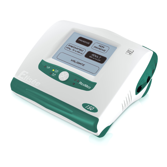
5.3 Programming ventilation options The Elisée 150 allows you to save two sets of ventilation parameters. From the main clinical screen you can modify the P1 and P2 programs (if the P2 activation option is set to yes, see "Parameter options screen" on page 91) or set the parameters for one or more ventilation options for a new patient. - Page 71 Choose between ventilation and between INVASIVE NON INVASIVE PAEDIATRIC ADULT ventilation by pressing the corresponding buttons. Selected patient configuration INVASIVE INVASIVE INVASIVE INVASIVE PAEDIATRIC PAEDIATRIC ADULT ADULT <25kg – 50 to 500ml <25kg – 50 to 500ml 300ml to 2,5 l 300ml to 2,5 l VALIDATE VALIDATE...
-
Page 72: Using The P1 And P2 Buttons
Using the P1 and P2 buttons On the main clinical screen, press the P1 icon to modify the P1 option or the P2 icon to modify the P2 option. Last test the 18/06/07 TEST TEST Double circuit : PASS P1: P1: P1: P1: P2: P2: PATIENT... -
Page 73: Modifying The Patient Configuration
Modifying the patient configuration From the ventilation parameter setting screen, you can modify the selected patient data by doing the following before starting ventilation: 1. Press the button on the right side of the ventilator. 2. Select New configuration. MENU MENU Configuration Options ... -
Page 74: Changing The Ventilation Mode
Changing the ventilation mode After selecting the patient configuration, you may change the selected ventilation mode at any time. 1. Press the Modes icon to go to the modes screen. Press to access the mode change P1 parameters setting e s s screen info PEEP... -
Page 75: Adjusting Ventilation Parameters
Adjusting ventilation parameters To adjust a value, press on the relevant icon. P1 parameters setting Cancel Cancel info PEEP PEEP 670 ml Vmax Vmax <PE Press to access the second and third parameter setting screens Figure 5.19: Ventilation parameters screen. Adjust the parameters by pressing "+"... - Page 76 Adjusting the pressure support parameters This function is available in the Synchronised Intermittent Mandatory Ventilation modes (SIMV and PSIMV). Press "PS" to display the pressure support settings screen. SIMV SIMV e s s P1 parameters setting info PEEP PEEP 670 ml Vmax Vmax PS icon...
- Page 77 Adjusting the apnea ventilation parameters This function is available in the pressure support modes (PS.SV (PS) and PS.VT) when the Fmini parameter has been set to no. 1. Press the Apnea icon to access the apnea ventilation settings screen. P1 parameters setting Cancel Cancel info...
- Page 78 5. Press "OK" to confirm the apnea ventilation configuration. The parameter setting screen will appear. e s s Ti = 1.7, I/E = 1/1.60 info Tapnea Tapnea <PS <PE Figure 5.25: Apnea ventilation validation screen. Adjusting the alarm thresholds e s s P1 parameters setting info PEEP...
- Page 79 e s s P1 parameters setting info 99 99 40 40 NO NO Press to return to parameter Pmax Pmax Leak Leak -- -- setting screen cmH2O 2400 2400 100 100 Example of alarm trigger threshold <PS --- --- Press to start ventilation <PE 10 10 17 17...
-
Page 80: Starting And Stopping Ventilation
Starting and stopping ventilation Ventilation can be started from the alarm thresholds screen or the parameter setting screen by pressing START VENTIL The device will begin to deliver ventilation and the curves screen will appear. e s s P1 parameters setting info PEEP PEEP... -
Page 81: Monitoring Ventilation
5.4 Monitoring ventilation You can monitor ventilation continuously using the following tools on the curves screen: • Bar graph; • Pressure and flow curves; • Four ventilation measurements; • symbol which appears below the bar graph when the trigger initiates a cycle. info Pressure curve Flow curve... -
Page 82: Measurements
Measurements To access the measurements screen, press one of the four measurements displayed at the bottom of the screen. info Measurements always displayed peak peak <PE <PE 23.2 1/3.3 Figure 5.32: Accessing the measurements display screen. All measurements are displayed on this screen. The four measurements displayed on the curves screen are highlighted. -
Page 83: Event Log
Event log A black box records the last 1,170 events. Note: Only ResMed technicians have access to the full log. 18 18 2007 2007 Monday June 11 : 00 : 48 11 : 00 : 48 Back Back Pb ON/OFF... - Page 84 Clinician's log The clinician's log provides clinicians with a filtered version of the Elisée 150 history contained in the full log. This screen can be accessed from any P1 or P2 clinical screen by pressing the button located on the right side of the device. Then press the buttons as shown in the screens below: MENU MENU...
-
Page 85: Table 5.1: Examples Of Log Events
The clinician's log sets out the following information, day by day: • Every triggering of an alarm; • The times when ventilation began and ended; • The type of power supply used; • The times when the ventilator was turned on and off. 18 18 2007 2007... -
Page 86: Preparing The Settings For Monitoring In Easyview 150
Preparing the settings for monitoring in Easyview 150 The Elisée 150 can record all ventilation measurements. The measurements are recorded over a period based on the recording time chosen by the user: Table 5.2: Trends sampling: the relationship between the recording time and the recording interval Recording time Recording interval 1 day... - Page 87 Programming the trends Note: This screen does not appear when the trends are programmed for the first time. The screen shows: • Whether the trends are in progress or completed; • The recording start date; • The recording time. If the trends have been completed, an additional line indicates whether or not the data has been downloaded.
- Page 88 Be careful all former data will be erased ! Do you want to continue ? <PE <PE Figure 5.39: "Trends: former data will be erased" screen. As a precaution, a final screen appears, reminding you that the former data will be erased if a new recording is programmed.
-
Page 89: Changing Mode During Ventilation
5.5 Changing mode during ventilation This option allows you to change the ventilation mode without stopping ventilation. Press the icon to change mode during ventilation. info peak peak <PE <PE 23.2 1/3.3 Figure 5.40: "Changing mode during ventilation" screen. The highlighted icon corresponds to the current ventilation mode. Press the icon which corresponds to the desired ventilation mode. - Page 90 24 24 Press to return to previous screen Mode setting/validate Cancel Cancel info Shows the previous ventilation mode and the new ventilation PEEP PEEP mode selected ┘HP Slope Slope Fmini Fmini <PE Apnea Apnea Figure 5.42: New mode settings screen. To adjust a value, press the icon for the corresponding parameter.
-
Page 91: Parameter Options Parameter Options Screen
5.6 Parameter options Parameter options screen Accessing the parameter options screen To reach this screen, press the button on the right side of the ventilator. Then press the buttons as shown in the screens below: MENU MENU Configuration Options Back Press to access menu Pause (stop ventilation) <... -
Page 92: Description Of The Parameter Options
Parameter options screen Parameters option Cancel Cancel info BTPS correction P2 activation <PS Select ACV parameter: <PE Ti Ti Vmax Vmax Figure 5.46: Parameter options screen. Press "YES" to activate an option or "NO" to deactivate it. To select the ACV parameter, press the Ti, max or I/E icon. The icons for the selected options are highlighted. -
Page 93: Specific Settings Calibrating The Touch Screen
5.7 Specific settings Calibrating the touch screen 1. Go to the main clinical screen. Last test the 18/06/07 TEST TEST Double circuit : PASS P1: P1: P1: P1: P2: P2: PATIENT PATIENT Figure 5.47: Main Clinical mode screen. 2. Press the button and the Alarm Silence button simultaneously until the following screen appears. -
Page 94: Empty Curves/Filled Curves
Empty curves/filled curves During ventilation, you can choose to view pressure and flow curves empty or filled in. To make your selection, go to the alarms or parameters screens. Once ventilation has started, press the icon for two seconds. When you release the icon, the curves screen will appear and the curves configuration can be changed. -
Page 95: Screen Brightness And Digital Sound (Volume Level)
Screen brightness and digital sound (volume level) Accessing the setting screen The brightness, the screen orientation, the touch screen beeps and the digital sound volume can all be adjusted on the setting screens. To access these screens, press the button on the right side of the ventilator. Then press the buttons as shown in the screens below: MENU MENU... - Page 96 Setting Back Back info Screen orientation modified Turning on or off the touch screen beeps Screen brightness adjustment Digital sound adjustment Figure 5.51: Digital sound adjustment screen. Press the scales to obtain the desired values for brightness and volume. If automatic screen brightness adjustment is selected (using the AUTO icon) the Elisée 150 automatically adjusts the screen brightness according to the ambient lighting.
-
Page 97: Date And Time
Date and time Accessing the setting screen To access these screens, press the button on the right side of the ventilator. Then press the buttons as shown in the screens below: MENU MENU Configuration Options Back Press to access menu Pause (stop ventilation) <... - Page 98 Cancel Cancel info 18 18 Monday June Date and time display 2007 2007 13: 02 :03 13: 02 :03 ┘HP Press these icons to position cursor <PE Soft version : 2.36 Figure 5.53: Date and time setting screen. Position the cursor on the value to be changed. Press "+"...
-
Page 99: Assigning Program Names
Assigning program names The clinician can assign names to programs P1 and P2 to help the patient distinguish between them. Accessing the program naming screen To access these screens, press the button on the right side of the ventilator. Then press the buttons as shown in the screens below. MENU MENU Configuration... - Page 100 Note: If the Elisée 150 is delivering ventilation, there is no need to stop ventilation before naming the programs. Naming the programs Replace the program name?: Back Back <PS Press to exit this screen CANCEL CANCEL <PE Figure 5.55: Accessing the program name replacement screen. On the first screen, select the program to be named.
- Page 101 Monday 18 18 June Monday June 9:58:46 9:58:46 Intern. tern. Customised ventilation program P1: P1: names START START P2: P2: VENTIL VENTIL NIGHT 1s 1s Figure 5.57: Ventilation program names screen. Naming the ventilation programs helps patients to familiarise themselves more quickly with their different ventilation options.
-
Page 102: Exiting The Clinical Screens
5.8 Exiting the clinical screens To return to the patient screens from any clinical screen, press the padlock icon. Note: As a safety measure, the icon must be pressed for at least 1 second. Press padlock to access patient screens info peak peak... -
Page 103: Patient Use
6 Patient use 6.1 Main patient screen From the main patient screen, the patient can choose between P1 and P2 ventilation (if "P2 activation" is set to YES – see "Parameter options" on page 91). Monday 18 18 June Monday June 9:58:46 9:58:46... -
Page 104: Patient Mode Settings Screen
6.2 Patient mode settings screen To see the ventilation settings for a pre-programmed option, press the relevant icon twice. Monday 18 18 June Monday June 9:58:46 9:58:46 Intern. tern. Press the selected icon to see P1: P1: the corresponding settings START START P2: P2:... -
Page 105: Starting And Stopping Ventilation In Patient Mode
6.3 Starting and stopping ventilation in patient mode Starting ventilation in patient mode To start ventilation, select the desired pre-programmed ventilation option, then press "S TART ". ENTIL Note: As a safety measure, the icon must be pressed for at least 1 second to start ventilation. Monday 18 18 June Monday... -
Page 106: Measurements Screen
6.4 Measurements screen To see the current settings and measurements, press the icon for the ventilation option currently in operation. 33. 6 Wednesday February 11: 28: 31 intern. Mains Press this icon to see the corresponding settings < HP < PE Figure 6.6: "Access to parameter review in patient mode during ventilation"... -
Page 107: Changing Ventilation Program During Ventilation
6.5 Changing ventilation program during ventilation Note: The ventilation program can be changed during ventilation only if the "P2 activation" option is set to "YES" (see "Parameter options" on page 91). On the patient ventilation screen, the icon for the current ventilation option is greyed out. To change the selected program, press the icon which is not greyed out. -
Page 108: Screen Brightness/Digital Sound Volume
6.6 Screen brightness/Digital sound volume Accessing the setting screen The brightness and orientation of the screen can be adjusted. You can also activate the emission of a beep each time the touch screen is pressed, and adjust the volume of the digital sound. To access this screen, press and hold the Alarm Silence button for at least three seconds. -
Page 109: Calibrating The Touch Screen
6.7 Calibrating the touch screen 1. Go to the main patient screen and stop ventilation. Monday 18 18 June Monday June 9:58:46 9:58:46 Intern. tern. P1: P1: START START P2: P2: VENTIL VENTIL 1s 1s Figure 6.10: "Access to screen calibration in patient mode" screen. 2. -
Page 110: Power Supply And Patient Timer Information
6.8 Power supply and patient timer information Power supply On the main patient screen the user can see the power status of the ventilator. Monday 18 18 June Monday June 9:58:46 9:58:46 Power status information Intern. tern. P1: P1: START START P2: P2: VENTIL... -
Page 111: Patient Timer
Patient timer On the patient settings and measurements screens the user can see the total length of time for which the patient has received ventilation. The timer ticks over during ventilation and is reset to zero when the device is reprogrammed for a new patient. - Page 112 112/174 NOT013189-6...
-
Page 113: Alarms
7 Alarms 7.1 Monitoring the alarms To ensure the patient's safety, when an alarm is triggered the user is alerted by: • An audible alert: the alert depends on the alarm priority. The beeps are made by two buzzers (86dBA at 1m and 78dBA at 3m) and a digital sound system with adjustable volume. •... -
Page 114: List Of Ventilation Monitoring Alarms
7.2 List of ventilation monitoring alarms Note: The alarms stop once the batteries start charging (i.e. as BATTERY EMPTY BATTERY LOW soon as the Elisée 150 is connected to the mains supply or an external DC supply). Table 7.2: List of ventilation monitoring alarms Alarm Trigger Alarm... - Page 115 Alarm Trigger Alarm Icon Message Time to trigger priority threshold Minimum MINI FiO2. High priority. Alarm setting. 30 seconds FiO2. below alarm threshold. Maximum MAXI FiO2. High priority. Alarm setting. 30 seconds FiO2. above alarm threshold. Leak. MAXI Leaks. High priority. Alarm setting.
-
Page 116: General Alarms Causes And Remedies
7.3 General alarms causes and remedies Table 7.3: Audible alarms which cannot be turned off Message Icon Alarm priority Cause Remedy INT BATT EMPTY. High priority. Internal battery Change power charge less than supply. INT. MINI FiO2. High priority. Supplied FiO Adjust rotameter low. - Page 117 Message Icon Alarm priority Cause Remedy INT BATT Medium priority. Internal battery Change power LOW. charge less than supply. 15%. INT. CIRCUIT High priority. Faulty connection Reconnect patient OPEN. of patient circuit. circuit. LP LP CIRCUIT High priority. Defective patient Change patient OPEN.
-
Page 118: Table 7.5: Audible Alarms Which Can Be Turned Off
Message Icon Alarm priority Cause Remedy MAXI P inspi. High priority. Pressure in circuit Check alarm higher than High threshold is Pressure alarm correctly set and threshold. patient's airway is clear, and check patient circuit integrity. MAXI Vt. High priority. Tidal volume Check alarm higher than upper... - Page 119 Silence button. REPLACE Low priority. Turbine Return device to BLOWER. maintenance. ResMed service centre. ADJUST Low priority. Time setting lost. Set the time. CLOCK. Note: When the ventilator is powered by the mains power pack using an external power cord (with the pack outside its compartment), this is treated as an external power supply.
-
Page 120: Alarm Checking Procedure
7.4 Alarm checking procedure Before using the ventilator, check that all critical alarms are properly adjusted according to the ventilation parameters. All visual and audible alarms must be tested regularly to ensure they are working properly, particularly prior to connection to a patient and before continuous ventilation. Testing the mains power and external DC power alarms Connect a patient circuit (single or double limb) fitted with a MAQUET test lung to the ventilator and perform the manual test. -
Page 121: Testing Settings Alarms For Use With Single Or Double Limb Circuits
Testing settings alarms for use with single or double limb circuits Connect a patient circuit (single or double limb) fitted with a MAQUET test lung to the ventilator and perform the manual test (see "Manual test" on page 65). Set up ACV mode, non-invasive, adult ventilation. Set the ventilation parameters as follows: •... -
Page 122: Table 7.8: Testing Oxygen Settings Alarms For Use With Single Or Double Limb Circuits
Table 7.8: Testing oxygen settings alarms for use with single or double limb circuits Visual alarm Audible alarm Time taken for Alarm Action status status alarm to trigger MAXI FIO2 Adjust alarm Flashing. Sounding. 30 seconds. upper threshold to = 30%. Adjust alarm Steady. -
Page 123: Table 7.9: Testing Apnea Ventilation Settings Alarms For Use With Single Or Double Limb Circuits
Table 7.9: Testing apnea ventilation settings alarms for use with single or double limb circuits Visual alarm Audible alarm Time taken for Alarm Action status status alarm to trigger PATIENT APNEA. Trigger pressure Sounding. Sounding. Tapnea = 15s. support cycle then wait without triggering an inspiratory phase. -
Page 124: Testing Settings Alarms For Use With A Double Limb Circuit
Testing settings alarms for use with a double limb circuit Connect a double limb patient circuit fitted with a MAQUET test lung to the ventilator and perform the manual test. Set up ACV mode, non-invasive, adult ventilation. Set the ventilation parameters as follows: •... -
Page 125: Testing Settings Alarms For Use With A Single Limb Circuit
Testing settings alarms for use with a single limb circuit Connect a single limb patient circuit fitted with a MAQUET test lung to the ventilator and perform the manual test. Set up ACV mode, non-invasive, adult ventilation. Set the ventilation parameters as follows: •... - Page 126 126/174 NOT013189-6...
-
Page 127: Maintenance And Disinfection
8 Maintenance and Disinfection Caution The device should be cleaned and disinfected before it is used for the first time, and also between patients. Note: In a hospital environment, we recommend the ventilator be disinfected regularly and also whenever contamination occurs. 8.1 Cleaning and maintenance frequency Cleaning frequency Any recommendations regarding the frequency for cleaning and replacing disposable parts will be... -
Page 128: Maintenance, Cleaning And Replacement Of Wearing Parts
8.2 Maintenance, cleaning and replacement of wearing parts Patient circuit and expiratory valve clapper For guidance on disinfecting and cleaning patient circuits, refer to the manufacturer's instructions. However, if a reusable patient circuit is being reused for the same patient, it can be cleaned regularly with soapy water, rinsed in clean water and then dried before use. -
Page 129: The Ventilator's Exterior
The ventilator’s exterior Clean the outside of the ventilator with a dry cloth or, if necessary, with a damp sponge. Figure 8.2: Cleaning the outside of the ventilator. Note: The ventilator may be decontaminated using current procedures approved by the service centres. -
Page 130: Replacing The Anti-Dust Filter
Replacing the anti-dust filter The filter is located at the rear of the ventilator. To replace it: 1. Use tweezers to pull the filter out of its compartment. 2. Insert the new filter into the compartment and push it in until flush with the casing. Note: R product ref. -
Page 131: Replacing The O2 Cell
Replacing the O cell Caution The replacement frequency for the O cell varies from 6 to 12 months. This frequency is given as an indication only and varies depending on the duration of ventilation, the oxygen concentration used and the ambient temperature. The O cell is located at the rear of the ventilator. - Page 132 Last test the 18/06/07 TEST TEST Double circuit : PASS P1: P1: P1: P1: P2: P2: PATIENT PATIENT Figure 8.6: Main clinical mode screen. The results of the last test are displayed. Press RESTART and follow the instructions displayed. Last test the 12/06/07 at 14 : 50 : 35 Back Circuit test : PASS...
-
Page 133: Double Limb Circuit Expiratory Support
Double limb circuit expiratory support Replacing the expiratory valve clapper The clapper must be replaced every time the support is sterilised or decontaminated. Note: R product ref. CLA007829. 1. To replace the clapper, dismantle the support as follows: Holding the two metal pins, press and turn to the left while holding the other end of the support steady. - Page 134 Autoclaving The supports may be autoclaved at 134°C for 18 minutes. Note: Before autoclaving the support, remove the clapper valve inside it. Decontamination Cold immersion decontamination may also be performed using a bactericidal, fungicidal and virucidal solution. 134/174 NOT013189-6...
-
Page 135: Technical Specifications And Description
Technical description Caution This section is intended for qualified technicians trained by ResMed. The Elisée 150 is a volumetric and pressure ventilator. The air flow is generated by a turbine from ambient air flowing through the air inlet. The Elisée 150 can therefore operate without a pressurised air supply. -
Page 136: Operation Of The Ventilator
Sensor Measurement range Internal temperature sensor. 0 – 100°C Hall-effect turbine speed sensor. 0 – 65,000rpm Operation of the ventilator Outside air is sucked in through an anti-dust filter. It may be enriched with oxygen using the low-pressure oxygen port (max 400kPa). The FiO monitored using a dedicated chemical sensor (if the oxygen monitoring option is activated). -
Page 137: Pressurised Air Flow Diagram - Single Limb Circuit
Pressurised air flow diagram – Single limb circuit Patient Expiratory valve sensor Expiratory flow Trigger Inspiratory flow sensor (Ptrig) sensor e sensor Safety Output pressure valve sensor (Pout) Insufflated air temperature sensor Stepper motor Printed Ventilation valve circuit board Optical sensor solenoid valve PEEP... -
Page 138: Pressurised Air Flow Diagram - Double Limb Circuit
Pressurised air flow diagram – Double limb circuit Patient Expiratory valve sensor Expiratory Trigger Inspiratory flow flow sensor (Ptrig) sensor i sensor e Safety Output pressure valve sensor (Pout) Air temperature sensor Stepper motor Printed ventilation valve circuit board Optical sensor solenoid valve PEEP... -
Page 139: Technical Specifications For The Elisée
9.2 Technical specifications for the Elisée 150 Electrical specifications • Device class: Class II, type BF . • Mains supply: 100VAC / 1 A to 230VAC / 0.6A – 50/60Hz. • External DC power supply: 12-28VDC, max 15A. • Internal Battery: Li-Ion; 14.4VDC; 6.3AH. •... - Page 140 Note: The batteries (internal and/or external) need to be fully charged before use. The batteries (internal and/or external) reach optimal life after three charge/discharge cycles. Recharging 5 - 6 hrs per battery. With an external power supply of < 19 +/- 1volts, the batteries do not recharge during ventilation.
-
Page 141: Table 9.3: Configuration Of The Relay According To The Operating Status Of The Device
Remote alarm Binder 3-pin female serial 712 connector Imax Vmax 1 (NC) 3 (NO) Ω 2 (COMMON) Figure 9.3: Remote alarm electrical connection. Remote alarm relay: • Interrupting capacity: Max. 10VA. • Max intensity: 0.5A. • Max voltage: 24VDC relative to earth or 0V for the device. Table 9.3: Configuration of the relay according to the operating status of the device Ventilator running with no Ventilator running with alarm... -
Page 142: Pressurised Air Specifications
Pressurised air specifications Low-pressure O port • Maximum input pressure = 400kPa. • Maximum input flow = 15L/min. Pressurised air interface • Female connection (built-in): 1.8 NPT threaded with clapper valve. CPC reference: MCD10-02. • Male connection (cord): CPC reference: MC22-03. Specifications and performance data Performance data •... - Page 143 Pressure • Maximum pressure: • 60hPa (= 60.96cmH O) in volumetric ventilation; • 60hPa (= 60.96cmH O) in pressure ventilation. To obtain these maximum pressures: • For pressure ventilation: Set up PACV with Pinsp = 50cmH O and PEEP = 10cmH O, and connect a double limb patient circuit fitted with a Maquet lung test to the device.
- Page 144 Materials Materials used • Anodised aluminium • Stainless steel • • Brass • Delrin • Silicone • Teflon • PPI foam • EPDM, Viton and PTFE seals. Material in contact with inhaled air • Anodised aluminium • Stainless steel • Delrin •...
-
Page 145: Operating, Storage And Transport Conditions
Conditions for transport without ventilation When returning to the service centre, the ventilator and its accessories must be transported inside the ResMed packaging. They must be transported in the following conditions: • Transport temperature: -10°C to +50°C;... -
Page 146: Technical Specifications For Accessories
• Liquid flow rate: 10 - 25mg/L. Anti-dust filter Specific ResMed equipment, ref. MOU010645. Note: The manufacturer accepts no liability for damage to the device caused by the use of a filter which does not comply with the recommendations. Remote alarm Specific ResMed equipment, ref. - Page 147 Serial link Specific ResMed equipment, ref. CAB012527. Note: The manufacturer accepts no liability for damage to the device caused by the connection of a cable which does not comply with the specifications provided. NOT013189-6 Technical Specifications and Description 147/174...
-
Page 148: Applicable Standards
9.4 Applicable standards The ventilator meets the following standards: • EN 60601-1:1990 / A1:1993 / A2:1995 / A13:1996: Medical Electrical Equipment. General Requirements for Safety; • EN 60601-1-2:2001: Electromagnetic Compatibility for Medical Electrical Equipment; • EN 55011, Class B, • EN 61000-4-2, •... -
Page 149: Appendices
10 Appendices 10.1 Spare parts and accessories Table 10.1: List of spare parts and accessories Description Reference Li-Ion external battery pack S/E013665 12-28V external power cord S/E012528 External power cord (linking mains power S/E011930 pack to Elisée) Double limb patient circuit with water trap CIR009727 Double limb circuit expiratory support S/E012629... -
Page 150: Parameters And Measurements Parameter Interdependence
10.2 Parameters and measurements Parameter interdependence Interaction between parameters and measurements (volumetric ventilation) The following table shows the interdependence between the parameters and measurements, or in other words all of the measurements which are affected when one parameter is changed. Table 10.2: Measurement interdependence Parameter Flow... -
Page 151: Table 10.4: Implicit Parameter Limits
Implicit (calculated) parameters Some parameters are adjustable, while others are calculated from the adjustable parameters. The latter are implicit parameters (e.g. Ti and F are adjustable parameters; the implicit setting Te = 60/F – Ti). The adjustable parameters are: Max flow ( max), Ti, Te and I/E. Note: Ti, I/E and max can be either adjustable or implicit parameters depending on the original configuration selected for the volumetric modes (parameter options). -
Page 152: Ranges Of Adjustment, Accuracies And Default Values
Ranges of adjustment, accuracies and default values Ventilation parameters Table 10.5: Range of adjustment for ventilation parameters Default values Range of adjustment Accuracy Incre- Value Minimum Maximum ment Patient type Paediatric Adult Paediatric Adult Paediatric Adult Ventilation type F (bpm) +/- 1 Ti (s) +/- 0.1... -
Page 153: Table 10.6: Range Of Adjustment For Triggers With Double Limb Circuit
Table 10.6: Range of adjustment for triggers with double limb circuit D e f a u l t v a l u e s M i n i m u m M a x i m u m P a e d i a t r ic A d u l t P a e d i a t r ic A d u l t... -
Page 154: Table 10.8: Range Of Adjustment And Default Values For Alarm Thresholds
Alarms Table 10.8: Range of adjustment and default values for alarm thresholds Default values Range of adjustment Value Minimum Maximum Increment Patient type Paediatric Adult Paediatric Adult Paediatric Adult Ventilation type Max. resp. rate (bpm) Max. pressure (cmH Max. V (mL) 2400 600-no... -
Page 155: Table 10.9: Ranges And Accuracy Of Measurements
Measurements Table 10.9: Ranges and accuracy of measurements Measurement (unit) Range Accuracy Display accuracy PEEP (cmH 0 to 100 +/- 5% Pmean (cmH 0 to 100 +/- 5% Ppeak (cmH 0 to 100 +/- 5% (%) with 100mL < Vt < 500mL 0 to 100 +/- 10% (%) with 500mL <... -
Page 156: Abbreviations And Symbols
10.3 Abbreviations and symbols Table 10.10: Definitions of abbreviations Abbreviation Definition PS.SV (PS) Pressure support with backup tidal volume PS.VT Pressure support with minimum tidal volume auto Automatic config. Configuration START VENTIL Start ventilation Respiratory rate Fraction of insufflated oxygen Ftot Total respiratory rate Ratio of inspiratory time to expiratory time... - Page 157 Abbreviation Definition SIMV Intermittent Assisted Volume-Controlled Ventilation (Synchronised Intermittent Mandatory Ventilation) Expired minute volume Ventil. Ventilation Minute volume expired during spontaneous cycles Maximum flow Spontaneous ventilation Tidal volume Backup tidal volume Expired tidal volume Inspired tidal volume NOT013189-6 Appendices 157/174...
-
Page 158: Table 10.11: Definitions Of Symbols
Table 10.11: Definitions of symbols Symbols Definitions External battery charge greater than 25% External battery charge greater than 50% External battery charge greater than 75% External battery full External battery missing Internal battery charge greater than 25% Internal battery charge greater than 50% Internal battery charge greater than 75% Internal battery full Internal battery empty... - Page 159 Symbols Definitions Adult Paediatric Invasive Non invasive Slope 1 Slope 2 Slope 3 Slope 4 Manufacturer’s address Recycling Constant flow rate Decreasing flow rate Mains supply or external DC supply LED Internal battery LED INT. External battery LED EXT. NOT013189-6 Appendices 159/174...
- Page 160 Symbols Definitions On/Off button Air insufflation Air return BF-type device Class II device Read the accompanying manuals DC voltage AC voltage CE-marked device Transport and storage position Fragile Keep dry Do not block (air inlet/outlet) 160/174 NOT013189-6...
- Page 161 Symbols Definitions Expiratory valve control Serial link Oxygen port Alarm Alarm Silence Serial number Relative humidity Proximal pressure line NOT013189-6 Appendices 161/174...
- Page 162 162/174 NOT013189-6...
- Page 163 NOT013189-6 Appendices 163/174...
- Page 164 164/174 NOT013189-6...
-
Page 165: List Of Figures
List of Figures Figure 2.1: Top view..............14 Figure 2.2: View of left side with double limb circuit expiratory support. - Page 166 Figure 4.23: SIMV mode............. . . 53 Figure 4.24: Mode PS.SV (PS), pressure increased to reach VTS.
- Page 167 Figure 5.52: Accessing the date and time settings......... . 97 Figure 5.53: Date and time setting screen.
- Page 168 168/174 NOT013189-6...
-
Page 169: List Of Tables
Configuration of the relay according to the operating status of the device... 141 Table 9.4: Operating principles for the ResMed BOI010525 remote alarm box....141 Table 10.1: List of spare parts and accessories . - Page 170 170/174 NOT013189-6...
-
Page 171: Index
Index Symbols Apnea adjusting parameters (A)CV alarm principle principle Apnea time Apnea ventilation Numerics Assisted controlled volume ventilation 12-28V DC power cord connection 12-28V external power cord Backup tidal volume reference Bar graph Battery alarm LEDs Abbreviations life Accessories recharging connecting switching manual test... - Page 172 technical specifications Double limb circuit expiratory support Flow shape maintenance Fmini maintenance frequency reference Double limb patient circuit reference Gas supply Event Events HME filter Expiratory support Humidifier attaching and removing cleaning frequency Expiratory time connecting Expiratory trigger Humidifier with patient circuit Expiratory valve clapper technical specifications maintenance...
- Page 173 description Parameters Mains power supply interdependence test Patient circuit Maintenance maintenance Materials Patient configuration in contact with inhaled air modifying in contact with oxygen PEEP used Power Max. flow of external DC supply Maximum flow Power consumption Maximum inspiratory time Power supply Measurements description...
- Page 174 Turning on Serial link symbol technical specifications Serial link cable Valve clapper reference fitting Serial number symbol Ventilation Serial port measurements Servicing monitoring frequency starting SIMV Ventilation mode principle changing Single limb circuit expiratory support Ventilation modes reference Ventilation parameters Single limb patient circuit adjusting connecting...
- Page 176 Global leaders in sleep and respiratory medicine www.ResMed.com...
Need help?
Do you have a question about the Elisee 150 and is the answer not in the manual?
Questions and answers