Table of Contents
Advertisement
Quick Links
Advertisement
Table of Contents

Related Manuals for Pilz PMCprimo C


Summary of Contents for Pilz PMCprimo C
- Page 1 PMCprimo C Control systems Operating instructions 1002242-EN-03...
- Page 2 Preface This document is a translation of the original document. All rights to this documentation are reserved by Pilz GmbH & Co. KG. Copies may be made for internal purposes. Suggestions and comments for improving this documentation will be gratefully received.
-
Page 3: Table Of Contents
4.1.6 Encoder 4.1.7 Reset button Software Section 5 Installation General requirements Dimensions Installing the unit Installing the fieldbus junction box Section 6 Wiring Wiring guidelines Connector pin assignment X40 Supply voltage Digital inputs Digital outputs Operating instructions PMCprimo C 1002242-EN-03... - Page 4 Absolute encoder with SSI interface Section 7 Commissioning Safety guidelines Commissioning the PMCprimo C 7.2.1 Preparing for commissioning 7.2.2 Establish communication PMCprimo C with PC 7.2.3 Adapt basic configuration of PMCprimo 7.2.4 Configure servo amplifier 7.2.5 Operate PMCprimo C Install CoDeSys...
- Page 5 Contents Section 9 Technical details PMCprimo C X/A/X/X 0.6 GHz CPU Section 10 Technical details PMCprimo C X/C/X/X 1.3 GHz CPU Section 11 Order reference 11.1 Product 11.2 Accessories Operating instructions PMCprimo C 1002242-EN-03...
-
Page 6: Introduction
Introduction Introduction Validity of the documentation This documentation is valid for the product PMCprimo C. It is valid until new documentation is published. This operating manual explains the function and operation, describes the installation and provides guidelines on how to connect the product PMCprimo C. - Page 7 It also highlights areas within the text that are of particular import- ance. INFORMATION This gives advice on applications and provides information on special fea- tures. Operating instructions PMCprimo C 1002242-EN-03...
-
Page 8: Overview
Overview Overview Unit features PMCprimo C is a motion controller used to automate multi-axis motion sequences. The device contains a PLC with the functionality of a logic and motion controller. Logic controller universally programmable in accordance with IEC 61131-3 Motion controller –... -
Page 9: Front View
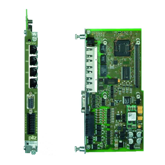
6: Ethernet TCP/IP interface 7: CANopen/PROFIBUS DP interface 8: Connection for encoder 9: Digital inputs/outputs and supply voltages 10: 2D code 11: Labelling strip – Order number – Serial number – Number of device version Operating instructions PMCprimo C 1002242-EN-03... -
Page 10: Type Code
Overview Type code Type Always state when ordering Supply voltage Order number PMCprimo C. _ / _ / _ / _ Servo amplifier Without 1.3 GHz Without Dynamic curve calculation IEC 61131-3 programming Path interpolation Fig.: Type code for PMCprimo C... -
Page 11: Scope Of Supply
PMCprimo C Expansion card for motion con- See "Type code" troller (for function range see "Type code") CD-ROM "Documentation Mo- Operating manual PMCprimo C, tion Control" Manuals for Pilz products from the PMC product area Operating instructions PMCprimo C 1002242-EN-03... -
Page 12: Security
Security Security Intended use The motion controller PMCprimo C is suitable for use in logic and motion control applica- tions. Examples of typical application areas for the product are Clocked production machinery Continuous manufacturing processes (winding, flying saw, cross cutter) -
Page 13: Warranty And Liability
EN 61131-2: Programmable controllers – Part 2: Equipment requirements and tests EN 61131-3: Programmable controllers – Part 3: Programming languages Please note this is not an exhaustive list of safety standards and directives. Where standards are undated, the 2010-12 latest editions shall apply. Operating instructions PMCprimo C 1002242-EN-03... -
Page 14: Function Description
Device properties 4.1.1 Controller The PMCprimo C is a drive-integrated programmable logic controller with motion control functionalities. The controller has volatile and non-volatile memory for the operating system, the data and the device project with the user program. It can be used for logic and motion control of intelligent drives. -
Page 15: Supply Voltage
Ethernet Fig.: Installation of the motion controller in a servo amplifier PMCprotego D 4.1.2 Supply voltage The PMCprimo C has two supply voltages: X40/7,15 Supply voltage for the device and the digital outputs (24 VDC) X40/8,16 Supply voltage for the encoder (5 V, 24 VDC) The voltage is connected directly to the female 9-pin D-Sub connector X41/4,9. -
Page 16: Digital Inputs
Real-time capable networking between CAN devices and the motion controller – Suitable for applications – with ≤ 16 subscribers – with cycle time of ≥ 1 ms – Connection to the servo amplifier PMCprotego D via the fieldbus junction box PMC- protego D.CAN-CANbus Adapter (supplied with the device) Operating instructions PMCprimo C 1002242-EN-03... - Page 17 SafetyNET p RTFL – SafetyNET p is an Ethernet-based multi-master bus system suitable for industrial use. It is suitable for real-time capable networking between the motion controller PMCprimo C and the servo amplifier PMCprotego D. – The PMCprimo C acts as Master –...
-
Page 18: Profibus Dp
The GSD file is available on the supplied CD-ROM. The name of the de- scription file can be found in the "Technical Details". INFORMATION Please also refer to the installation guidelines published by the PROFIBUS User Group. Operating instructions PMCprimo C 1002242-EN-03... -
Page 19: Ethernet
Function description 4.1.5.4 Ethernet The Gigabit Ethernet interface (X43) connects the PMCprimo C to a programming device for configuration, programming and commissioning. The interface can also be used to con- nect a visualisation device. The Gigabit Ethernet interface is compatible with 1000Base-T (Standard Gigabit Ethernet). -
Page 20: Encoder
(if a USB stick is inserted, any device data present will be copied, see Functions of the reset button.) Change from "RUN" operating status to "STOP" Change from "STOP" operating status to "RUN" INFORMATION For further information on the reset button see Operation. Operating instructions PMCprimo C 1002242-EN-03... -
Page 21: Software
CoDeSys packages the "PMC Programming Tool" also contains the target support packages and the PMCprimo base project. The software tools are available on the Internet at www.pilz.com. INFORMATION The "PMC Programming Tool" for IEC 61131-3 programming contains the CoDeSys Version 2.3.9.44. -
Page 22: Installation
The motion controller is installed in the servo amplifier PMCprotego D. Once installed, the environmental conditions of the servo amplifier PMCprotego D apply (see "Technical Details" in the operating manual for the servo ampli- fier). Dimensions 18,4 (0.72'') 97,4 (3.83'') Fig.: Dimensions, stated in mm (") Operating instructions PMCprimo C 1002242-EN-03... -
Page 23: Installing The Unit
Installation Installing the unit The PMCprimo C is installed in slots 1 and 2 of the servo amplifier PMCprotego D. When installing, please note the guidelines given under "Installation" in the operating manual for the servo amplifier. PMCprotego D.01 PMCprotego D.24 PMCprotego D.48... - Page 24 Connect the 9-pin female D-Sub connector X6D to the male connector X6 on the servo amplifier. Turn the screws into the thread on the housing. START RESET Fig.: Installing the fieldbus junction box on a servo amplifier Operating instructions PMCprimo C 1002242-EN-03...
-
Page 25: Wiring
Possible remedy: Use separate multicore cable for supply voltages. Use appropriate wiring to exclude short circuits between the outputs. The actuators may be connected using unshielded cables. The outputs do not need suppression for inductive loads. Cable material Use copper wiring. Operating instructions PMCprimo C 1002242-EN-03... -
Page 26: Connector Pin Assignment X40
Safe electrical isolation must be ensured for the external power supply that generates the supply voltage. Failure to do so could result in electric shock. The power supplies must comply with EN 60950-1, 05/2006, EN 61558-2-6, 11/1997. Operating instructions PMCprimo C 1002242-EN-03... -
Page 27: Digital Inputs
I1:1 Digital input 1 I1:2 Digital input 2 I1:3 Digital input 3 I1:4 Digital input 4 I1:5 Digital input 5 I1:6 Digital input 6 0 V Supply Reference earth for digital inputs Connector pin assignment Operating instructions PMCprimo C 1002242-EN-03... -
Page 28: Digital Outputs
Digital output 2 O1:3 Digital output 3 +24 V Supply voltage for digital outputs O1:4 Digital output 4 O1:5 Digital output 5 O1:6 Digital output 6 0 V Supply Reference earth for digital outputs Connector pin assignment Operating instructions PMCprimo C 1002242-EN-03... -
Page 29: Interfaces Overview
Depending on the unit type: - 2 CANopen interfaces - 1 CANopen/1 PROFIBUS DP interface (connection via fieldbus junction box on the servo amplifier PMCprotego D, see section entitled Device properties [ 14]) Socket assignment Operating instructions PMCprimo C 1002242-EN-03... -
Page 30: Canopen, Profibus Dp
The following table provides an approximate overview of the size of the terminating resistor with different cable lengths. In each specific case, details of the characteristic imped- ance can be found in the cable specification. Operating instructions PMCprimo C 1002242-EN-03... - Page 31 CAN2 high signal CAN2_L CAN2 low signal Ground CAN_H CAN1 high signal CAN_L CAN1 low signal n.c. = not connected Device type: 2 CANopen interfaces Connection via fieldbus junction box on the servo amplifier PMC- protego D Operating instructions PMCprimo C 1002242-EN-03...
-
Page 32: Canopen/Profibus Dp Interface
Socket X43 Designation Description TX D1+ TX D1- RX D2+ BI D3+ BI D3- RX D2- BI D4+ BI D4- The Ethernet interface is compatible with 1000Base-T (Standard Gigabit Ethernet) Recommended cable: Cat 5e SF/UTP Operating instructions PMCprimo C 1002242-EN-03... -
Page 33: Safetynet P Rtfl
The power supplies must comply with EN 60950-1, 05/2006, EN 61558-2-6, 11/1997. Connector X40 Designation Description Encoder Supply Supply voltage for external en- coder 0 V Encoder Supply Supply voltage for external en- coder (0 V) Supply voltage for encoder at X41 Connector pin assignment Operating instructions PMCprimo C 1002242-EN-03... - Page 34 Wiring Supply voltage X40/8 is linked internally to X41/4 and X40/16 to X41/9 Connection Operating instructions PMCprimo C 1002242-EN-03...
-
Page 35: Incremental Encoder With Ttl Signal
Channel A inverted Channel B inverted Reference pulse Z inverted 0 V Supply voltage 0 V n. c. = not connected Socket assignment Input circuit Incremental encoder Twisted pair, shielded Incremental encoder Shield connection in the housing Connection Operating instructions PMCprimo C 1002242-EN-03... -
Page 36: Absolute Encoder With Ssi Interface
Data inverted n. c. 0 V Supply voltage 0 V n c.: Not connected Socket assignment Input circuit Absolute encoder with SSI interface Shielded Encoder DATA DATA Shield connection in the housing DATA\ DATA\ CLOCK CLOCK CLOCK\ CLOCK\ Connection Operating instructions PMCprimo C 1002242-EN-03... -
Page 37: Commissioning
The heat sink and front plate temperature on the amplifier may reach 80°C during oper- ation. Check (measure) the temperature of the heat sink. Wait until the heat sink has cooled to 40°C before touching it. Operating instructions PMCprimo C 1002242-EN-03... -
Page 38: Commissioning The Pmcprimo C
680050 12 100001 +24 V PMCprotego D Fig.: Connect PMCprimo C and PMCprotego D, example 1 via CANopen/PROFIBUS interface Prerequisites: The motion controller PMCprimo C must be installed in a servo amplifier. A fieldbus junction box PMCprotego D.CAN-CANbus Adapter or PMCprotego D.CAN- PROFIBUS Adapter must be inserted. - Page 39 Example 2 via SafetyNET p RTFL interface: Connect PMCprimo C and PMCprotego D. SafetyNET p RTFL Fig.: Connect PMCprimo C and PMCprotego D, example 2 via SafetyNET p RTFL interface Prerequisites: The motion controller PMCprimo C must be installed in a servo amplifier.
-
Page 40: Establish Communication Pmcprimo C With Pc
You can now connect to a known network subscriber. If you do not know the IP address, you can browse the network for subscribers. Alternative 1: The IP settings are known Prerequisite: The PMCprimo C and PC must be in the same network or be accessible via a Router. 1. Select Ethernet. - Page 41 IP ad- 192.168.0.11 dress Netmask 255.255.255.0 Gateway 192.168.0.1 CHANNELS Number 1...32 HARDWARE Type: PMCprimo C 600MHz CAN/CAN Item No.: 680055 Ser. No.: Pr. Ver.: Encoder Inputs: Outputs: Virtual inputs: Virtual outputs: Analogue Inputs: Analogue Outputs: DEVICES in SafetyNET p RTFL Network:...
- Page 42 Control loop open Axis executes alignment movement Axis executes coupling process Initialisation running Axis executes positioning Axis executes stop command Axis is in speed control Axis is in standby Position assignment is active on the axis Operating instructions PMCprimo C 1002242-EN-03...
-
Page 43: Adapt Basic Configuration Of Pmcprimo
Exit menu Delete application data Change CAN1 baudrate Change Ethernet Change in/out length for Profibus Change offset for Profibus Set CAN1 Cycle time Set CAN address Change Profibus address Change number of channels Change CAN2 baudrate Operating instructions PMCprimo C 1002242-EN-03... -
Page 44: Configure Servo Amplifier
You can operate the motion controller in the commissioning software terminal by issuing commands in the command language. HW1 - Show Hardware 0.1: hw1 0.1: SOFTWARE Firmware: 3.2.0, Dec 16 2014, 13:20:52 Motion: INSTALLED IEC PLC: INSTALLED Interpolation: INSTALLED ETHERNET IP address 192.168.0.11 Netmask 255.255.255.0 Gateway 192.168.0.1 Operating instructions PMCprimo C 1002242-EN-03... - Page 45 Commissioning CHANNELS Number 1...32 HARDWARE Type: PMCprimo C 600MHz CAN/CAN Item No.: 680055 Ser. No.: Pr. Ver.: Encoder: Inputs: Outputs: Virtual In- puts: Virtual Out- puts: Analogue In- puts: Analogue Out- puts: DEVICES in CAN Network: PNOZmulti (DS401) at CAN1 ADDR 14 found.
-
Page 46: Install Codesys
The development environment for programming in accordance with IEC 61131-3 CoDeSys can be found in the software package "PMC Programming Tool". The software package is available on the Internet at www.pilz.de. Select the CoDeSys menu. Installation will start. Follow the instructions. -
Page 47: Operation
- RS4 RS2 or - RS5 reset button - RS6 No user program Error detected HW reset: - RS1 - Reset button STOP Fig.: Operating states and changes in operating status of the motion controller Operating instructions PMCprimo C 1002242-EN-03... -
Page 48: Operating States
"RUN" operating status In "RUN" operating status All system sections are in a RUN condition and are operating faultlessly. A PLC user program is run as part of each cycle. Status of LED: The LED flashes slowly. Operating instructions PMCprimo C 1002242-EN-03... -
Page 49: Stop" Operating Status
"Startup" operating status has been run without error. The system changes to "STOP" status if no user program was loaded in "Startup" status. --> Change from "Startup" to "Fatal Error" The system changes to "Fatal Error" status if an error occurred in "Startup" status. Operating instructions PMCprimo C 1002242-EN-03... - Page 50 Holding down the reset button for a short period (< 4 s) (alternative to RS2 command (change to "RUN")). --> Change from "STOP" to "Fatal Error" The system changes to "Fatal Error" status if an error occurred in "STOP" status. Operating instructions PMCprimo C 1002242-EN-03...
-
Page 51: Reset, Restart, Start And Stop Options
The following table provides an overview of the impact of a reset, start or stop on a vari- able. Variable with attrib- Variable with attrib- Variable with attrib- RETAIN PERSIST- Action ute RETAIN ute PERSISTENT Warm reset Cold reset Original reset Operating instructions PMCprimo C 1002242-EN-03... -
Page 52: Cold Start, "Startup
Resets all variables to the value with which they were initialised (including remanent variables with attribute RETAIN and PERSISTENT). Resets the motion controller to its original condition (factory defeault settings). Commands: Command language: RS6 IEC 61131 programming: Menu Online -> Reset (original) Operating instructions PMCprimo C 1002242-EN-03... -
Page 53: Start And Stop Commands
The LED lights for 4 s continuously after "Startup" has been run. During this time it's possible to change to "Boot Menu" operating status. Press the reset button while the LED is lit continuously. The controller changes to "Boot Menu". Operating instructions PMCprimo C 1002242-EN-03... -
Page 54: Messages
Display commands can be ex- ecuted in the operating status "RUN" and "STOP". To start display mode, select the DM command in the terminal program. To end display mode, select the DO command in the terminal program. Operating instructions PMCprimo C 1002242-EN-03... - Page 55 Operation Process data Process data can be recorded in the operating status "RUN" and "STOP" via the Motion controller Terminal program. Oscilloscope function PScope. Operating instructions PMCprimo C 1002242-EN-03...
-
Page 56: Display Elements
CAN1 CAN1 No network connection Network connection is error-free Meaning LINK Network connection is error-free SafetyNET p LINK Green No network connection TRAFFIC Ethernet LINK TRAFFIC Data traffic is error-free Yellow No data traffic TRAFFIC Operating instructions PMCprimo C 1002242-EN-03... - Page 57 Operation Legend LED on LED off LED flashes Operating instructions PMCprimo C 1002242-EN-03...
-
Page 58: Technical Details Pmcprimo C X/A/X/X 0.6 Ghz Cpu
Technical details PMCprimo C X/A/X/X 0.6 GHz CPU Technical details PMCprimo C X/A/X/X 0.6 GHz CPU General 680050 680060 Approvals Application range Standard Standard Electrical data 680050 680060 Supply voltage Supply Supply Voltage 24 V 24 V Kind -15 %/+20 %... - Page 59 Technical details PMCprimo C X/A/X/X 0.6 GHz CPU Inputs 680050 680060 Input voltage in accordance with 24 V DC 24 V DC EN 61131-2 Type 1 Input current range 3,5 - 10,8 mA 3,5 - 10,8 mA Potential isolation Semiconductor outputs...
- Page 60 Technical details PMCprimo C X/A/X/X 0.6 GHz CPU Ethernet interface 680050 680060 Potential isolation Environmental data 680050 680060 EN 60068-2-1, EN 60068-2-14, EN EN 60068-2-1, EN 60068-2-14, EN Climatic suitability 60068-2-2, EN 60068-2-78 60068-2-2, EN 60068-2-78 Ambient temperature In accordance with the standard EN 60068-2-14...
- Page 61 Technical details PMCprimo C X/A/X/X 0.6 GHz CPU Potential isolation 680050 680060 Type of potential isolation Basic insulation Basic insulation Rated surge voltage 500 V 500 V Potential isolation between SC output and system voltage SC output and system voltage...
-
Page 62: Technical Details Pmcprimo C X/C/X/X 1.3 Ghz Cpu
Technical details PMCprimo C X/C/X/X 1.3 GHz CPU Technical details PMCprimo C X/C/X/X 1.3 GHz CPU General 680160 680170 Approvals Application range Standard Standard Electrical data 680160 680170 Supply voltage Supply Supply Voltage 24 V 24 V Kind -15 %/+20 %... - Page 63 Technical details PMCprimo C X/C/X/X 1.3 GHz CPU Inputs 680160 680170 Input voltage in accordance with 24 V DC 24 V DC EN 61131-2 Type 1 Input current range 3,5 - 10,8 mA 3,5 - 10,8 mA Potential isolation Semiconductor outputs...
- Page 64 Technical details PMCprimo C X/C/X/X 1.3 GHz CPU Ethernet interface 680160 680170 Potential isolation Environmental data 680160 680170 EN 60068-2-1, EN 60068-2-14, EN EN 60068-2-1, EN 60068-2-14, EN Climatic suitability 60068-2-2, EN 60068-2-78 60068-2-2, EN 60068-2-78 Ambient temperature In accordance with the standard EN 60068-2-14...
- Page 65 Technical details PMCprimo C X/C/X/X 1.3 GHz CPU Potential isolation 680160 680170 Type of potential isolation Basic insulation Basic insulation Rated surge voltage 500 V 500 V Potential isolation between SC output and system voltage SC output and system voltage...
-
Page 66: Order Reference
PROFIBUS interface for PMCprotego D.01 … D.24 01-24A incl. RJ45 con- nection cable PMCprotego D.CAN- Fieldbus juction box with one CANopen interface and one 680043 PROFIBUS Adapter PROFIBUS interface for PMCprotego D.48/D.72 48-72A incl. RJ45 con- nection cable Operating instructions PMCprimo C 1002242-EN-03... - Page 67 Front cover Support Technical support is available from Pilz round the clock. Americas Australia Scandinavia Brazil +61 3 95446300 +45 74436332 +55 11 97569-2804 Spain Canada Europe +34 938497433 +1 888-315-PILZ (315-7459) Austria Switzerland +41 62 88979-30 Mexico +43 1 7986263-0...
Need help?
Do you have a question about the PMCprimo C and is the answer not in the manual?
Questions and answers