
Related Manuals for Pilz PNOZ m ES Profinet


Summary of Contents for Pilz PNOZ m ES Profinet
- Page 1 PNOZ m ES Profinet Configurable Control System PNOZmulti Operating Manual1003386EN02...
- Page 2 Preface This document is the original document. All rights to this documentation are reserved by Pilz GmbH & Co. KG. Copies may be made for internal purposes. Suggestions and comments for improving this documentation will be gratefully received. Pilz®, PIT®, PMI®, PNOZ®, Primo®, PSEN®, PSS®, PVIS®, SafetyBUS p®, SafetyEYE®, SafetyNET p®, the spirit of safety® are registered and protected trademarks of Pilz GmbH & Co. KG in some countries. SD means Secure Digital...
-
Page 3: Table Of Contents
Content Section Section 1 Introduction Validity of documentation Using the documentation Definition of symbols Section 2 Overview Scope of supply Unit features Front view Section 3 Safety Intended use System requirements Safety regulations 3.3.1 Use of qualified personnel 3.3.2 Warranty and liability 3.3.3 Disposal 3.3.4 For your safety Section 4 Function description Operation Data access Assigning the inputs/outputs in the PNOZmulti Configurator to the PROFINET inputs/outputs Block diagram Section 5 Installation General installation guidelines Connect the base unit and expansion modules Dimensions Section 6 Commissioning General wiring guidelines Connecting the supply voltage Interface assignment Preparing for operation... - Page 4 Content Section 9 Order reference Module Accessories Operating Manual PNOZ m ES Profinet 1003386EN02...
-
Page 5: Introduction
Introduction Introduction Validity of documentation This documentation is valid for the product PNOZ m ES Profinet. It is valid until new docu mentation is published. This operating manual explains the function and operation, describes the installation and provides guidelines on how to connect the product. Using the documentation This document is intended for instruction. Only install and commission the product if you have read and understood this document. The document should be retained for future ref erence. Definition of symbols Information that is particularly important is identified as follows: DANGER! This warning must be heeded! It warns of a hazardous situation that poses an immediate threat of serious injury and death and indicates preventive measures that can be taken. WARNING! This warning must be heeded! It warns of a hazardous situation that could lead to serious injury and death and indicates preventive measures that can be taken. CAUTION! This refers to a hazard that can lead to a less serious or minor injury plus material damage, and also provides information on preventive measures that can be taken. NOTICE This describes a situation in which the product or devices could be dam aged and also provides information on preventive measures that can be taken. It also highlights areas within the text that are of particular import ance. Operating Manual PNOZ m ES Profinet 1003386EN02... - Page 6 Introduction INFORMATION This gives advice on applications and provides information on special fea tures. Operating Manual PNOZ m ES Profinet 1003386EN02...
-
Page 7: Overview
Overview Overview Scope of supply Unit features Using the product PNOZ m ES Profinet: Expansion module for connection to a base unit from the configurable control system PNOZmulti 2 . The product has the following features: Can be configured in the PNOZmulti Configurator Connections for PROFINET status, diagnostic and error displays for communication with PROFINET 128 virtual inputs and outputs on the control system PNOZmulti 2 can be defined in the PNOZmulti Configurator for communication with the fieldbus PROFINET. Transmission rate 100 MBit/s (100BaseTX), full and half duplex Max. 1 PNOZ m ES Profinet can be connected to the base unit Two RJ45 ports Profinet IO device (V2.2) functions in accordance with Conformance Class C Supported functions: – – – – LLDP – I&M 04 Plugin connection terminals: either springloaded terminal or screw terminal available as an accessory (see order reference) Please refer to the document "PNOZmulti System Expansion" for details of the base units PNOZmulti 2 that can be connected. Operating Manual PNOZ m ES Profinet 1003386EN02... -
Page 8: Front View
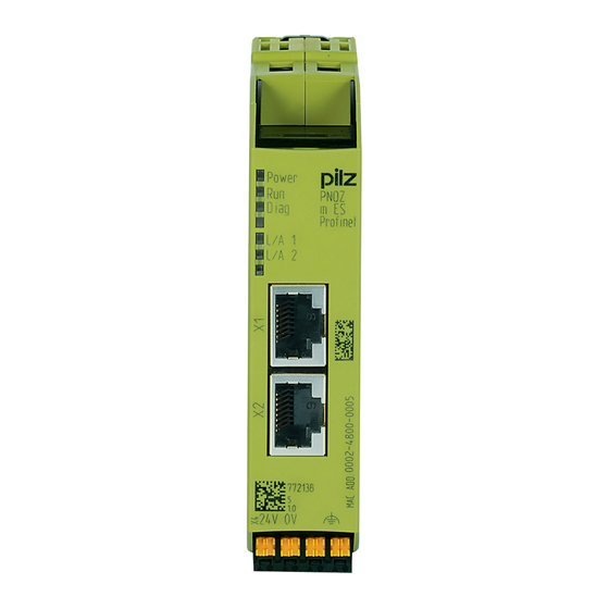
Overview Front view Legend: X1, X2: Profinet interfaces 0 V, 24 V: Supply connections : Functional earth LED: – Power – – Diag – L/A 1 – L/A 2 Operating Manual PNOZ m ES Profinet 1003386EN02... -
Page 9: Safety
Safety Safety Intended use The expansion module PNOZ m ES Profinet is used for communication between the config urable control system PNOZmulti 2 with the PROFINET. PROFINET is designed for fast data exchange at field level. The expansion module PNOZ m ES Profinet is a passive subscriber (IO device) of the PROFINET. The basic communica tion functions with the PROFINET conform to the System Description published by the PROFIBUS & PROFINET International (PI) User Group. The central controller (IO control ler) reads input information from the IO devices and writes output information to the IO devices as part of each cycle. As well as the cyclical transfer of usable data PROFINET can also be used for diagnostics and commissioning functions. Data traffic is monitored on the IO controller and IO device side. The expansion module may only be connected to a base unit from the configurable control system PNOZmulti 2 (please refer to the document "PNOZmulti System Expansion" for de tails of the base units that can be connected). The configurable control system PNOZmulti 2 is used for the safetyrelated interruption of safety circuits and is designed for use in: ESTOP equipment Safety circuits in accordance with VDE 0113 Part 1 and EN 602041 The expansion module may not be used for safetyrelated functions. The following is deemed improper use in particular: Any component, technical or electrical modification to the product Use of the product outside the areas described in this manual Use of the product outside the technical details (see chapter entitled "Technical De tails"). NOTICE EMCcompliant electrical installation The product is designed for use in an industrial environment. The product may cause interference if installed in other environments. If installed in other environments, measures should be taken to comply with the applicable standards and directives for the respective installation site with regard to in terference. System requirements Please refer to the "Product Modifications" document in the "Version overview" section for details of which versions of the base unit and PNOZmulti Configurator can be used for this product. Operating Manual PNOZ m ES Profinet 1003386EN02... -
Page 10: Safety Regulations
Safety Safety regulations 3.3.1 Use of qualified personnel The products may only be assembled, installed, programmed, commissioned, operated, maintained and decommissioned by competent persons. A competent person is someone who, because of their training, experience and current pro fessional activity, has the specialist knowledge required to test, assess and operate the work equipment, devices, systems, plant and machinery in accordance with the general standards and guidelines for safety technology. It is the company’s responsibility only to employ personnel who: Are familiar with the basic regulations concerning health and safety / accident preven tion Have read and understood the information provided in this description under "Safety" And have a good knowledge of the generic and specialist standards applicable to the specific application. 3.3.2 Warranty and liability All claims to warranty and liability will be rendered invalid if The product was used contrary to the purpose for which it is intended Damage can be attributed to not having followed the guidelines in the manual Operating personnel are not suitably qualified Any type of modification has been made (e.g. exchanging components on the PCB boards, soldering work etc.). 3.3.3 Disposal When decommissioning, please comply with local regulations regarding the disposal of electronic devices (e.g. Electrical and Electronic Equipment Act). 3.3.4 For your safety The unit meets all the necessary conditions for safe operation. However, you should always ensure that the following safety requirements are met: This operating manual only describes the basic functions of the unit. The expanded functions are described in the PNOZmulti Configurator's online help. Only use these functions once you have read and understood the documentations. Do not open the housing or make any unauthorised modifications. Please make sure you shut down the supply voltage when performing maintenance work (e.g. exchanging contactors). Operating Manual PNOZ m ES Profinet 1003386EN02... -
Page 11: Function Description
Function description Function description Operation The virtual inputs and outputs that are to be transferred via PROFINET are selected and configured in the PNOZmulti Configurator. The base unit and the expansion module PNOZ m ES Profinet are connected via a jumper. After the supply voltage is switched on or the PNOZmulti 2 is reset, the expansion module PNOZ m ES Profinet is configured and started automatically. LEDs indicate the status of the fieldbus module PROFINET. The configuration is described in detail in the PNOZmulti Configurator's online help. INFORMATION The GSDML file is available on the Internet at www.pilz.de. Data access The data is structured as follows: Virtual data – Input area PNOZ m ES Profinet The values for the inputs are set as an output in the Master and transferred to the PNOZmulti 2. – Output range PNOZ m ES Profinet The outputs are configured in the PNOZmulti Configurator and transferred to the Master. Status of LEDs: Bit 0 … 4: Status of LEDs on the PNOZmulti 2 – Bit 0: OFAULT – Bit 1: IFAULT – Bit 2: FAULT – Bit 3: DIAG – Bit 4: RUN Data exchange is displayed in Bit 5. Polling the usable data: 2 Bytes with the table number and segment number are sent by the Master for access to the usable data table (15 Bytes are returned to the Master). Detailed information on data exchange (tables, segments) is available in the document "Communication Interfaces" in the section entitled "Fieldbus modules". -
Page 12: Assigning The Inputs/Outputs In The Pnozmulti Configurator To The
Function description Assigning the inputs/outputs in the PNOZmulti Configurator to the PROFINET inputs/outputs Virtual inputs and outputs can be requested or set directly via the following objects. Each element can be selected individually in the master control system, e.g. virtual inputs i031. The data width is also established this way. Input data The Master writes to the virtual inputs of the PNOZmulti 2. Description Input data from PNOZmulti 2 Virtual inputs i0 – i31 4 Input Bytes Virtual inputs i32 – i63 4 Input Bytes Virtual inputs i64 – i95 4 Input Bytes Virtual inputs i96 – i127 4 Input Bytes Output data The Master reads the virtual outputs of the PNOZmulti 2. Description Output data from PNOZmulti 2 Virtual outputs o0 – o31 4 Output Bytes Virtual outputs o32 – o63 4 Output Bytes Virtual outputs o64 – o95 4 Output Bytes Virtual outputs o96 – o127 4 Output Bytes Block diagram 24V 0V FE 24V 0V Operating Manual PNOZ m ES Profinet 1003386EN02... -
Page 13: Installation
Installation Installation General installation guidelines The unit should be installed in a single mounting area with a protection type of at least IP54. Fit the safety system to a horizontal mounting rail. The venting slots must face upwards and downwards. Other mounting positions could destroy the safety system. Use the locking slide on the rear of the unit to attach it to a mounting rail. In environments exposed to heavy vibration, the unit should be secured using a fixing element (e.g. retaining bracket or end angle). Open the locking slide before lifting the unit from the mounting rail. To comply with EMC requirements, the mounting rail must have a low impedance con nection to the control cabinet housing. The ambient temperature of the PNOZmulti units in the control cabinet must not exceed the figure stated in the technical details, otherwise air conditioning will be required. NOTICE Damage due to electrostatic discharge! Electrostatic discharge can damage components. Ensure against discharge before touching the product, e.g. by touching an earthed, conductive sur face or by wearing an earthed armband. Connect the base unit and expansion modules Connect the base unit and the expansion module as described in the operating instructions for the base units. Connect the black/yellow terminator to the expansion module. Install the expansion module in the position in which it is configured in the PNOZmulti Configurator. Operating Manual PNOZ m ES Profinet 1003386EN02... -
Page 14: Dimensions
Installation Dimensions 22,5 101,4 (4,11“) (0,88“) Operating Manual PNOZ m ES Profinet 1003386EN02... -
Page 15: Commissioning
Commissioning Commissioning General wiring guidelines The wiring is defined in the circuit diagram of the PNOZmulti Configurator. It is possible to define which inputs and outputs on the safety system will communicate with PROFINET. Please note: Information given in the "Technical details [ 20]" must be followed. Use copper wiring with a temperature stability of 75 °C. Please note the following when connecting to PROFINET: The following minimum requirements of the connection cable and connector must be met: – Only use standard industrial Ethernet cable and connectors. – Only use doubleshielded twisted pair cable and shielded RJ45 connectors (indus trial connectors). – 100BaseTX cable in accordance with the Ethernet standard (min. Category 5) Measures to protect against interference: Ensure the requirements for the industrial use of PROFINET are met, as stated in the Installation Manual published by the User Group. External measures must be used to connect the terminal to the functional earth, when the mounting rail is not connected to the functional earth. Always connect the mounting rail to the protective earth via an earthing terminal. This will be used to dissipate hazardous voltages in the case of a fault. The power supply must meet the regulations for extra low voltages with protective sep aration. CAUTION! Only connect and disconnect the expansion module when the supply voltage is switched off. NOTICE When installing, you must refer to the guidelines published by the RPOFIBUS & PROFINET International (PI) User Group. Connecting the supply voltage Connect the supply voltage to the fieldbus module: Terminal 24 V: + 24 V DC Terminal 0 V: 0 V Operating Manual PNOZ m ES Profinet 1003386EN02... -
Page 16: Interface Assignment
Commissioning Interface assignment RJ45 socket 8pin Standard TD+ (Transmit+) TD (Transmit) RD+ (Receive+) n.c. n.c. RD (Receive) n.c. n.c. n.c.: Not connected Preparing for operation 6.4.1 Download modified project to the PNOZmulti safety system As soon as an additional expansion module has been connected to the system, the project must be amended using the PNOZmulti Configurator. Proceed as described in the operat ing instructions for the base unit. NOTICE For the commissioning and after every program change, you must check whether the safety devices are functioning correctly. 6.4.2 Set IP address There are two options: Automatic assignment of the IP address with the Dynamic Host Configuration Protocol (DHCP) Assignment of the IP address by the IO controller before system startup based on the unique unit name. 6.4.3 Install GSDLM file Install the GDSML file. You can find the GSDML file in the Internet at www.pilz.de. Operating Manual PNOZ m ES Profinet 1003386EN02... -
Page 17: Connection Example
Commissioning Connection example PROFINET Controller PROFINET PROFINET PROFINET Device 1 Device 2 Device 3 Operating Manual PNOZ m ES Profinet 1003386EN02... -
Page 18: Operation
Operation Operation Messages When the supply voltage is switched on, the PNOZmulti safety system copies the configur ation from the chip card. The LEDs “POWER”, “DIAG”, “FAULT”, “IFAULT” and “OFAULT” will light up on the base unit. The expansion module PNOZ m ES Profinet is configured and started automatically. The LEDs "RUN" and "ERR" display the status of the PNOZ m ES Profinet at the PROFINET. If the expansion module PNOZ m ES Profinet does not receive a configuration from the base unit for a period of 30 s, the expansion module PNOZ m ES Profinet connects to the IO controller and "RUN" status is displayed on PROFINET. The error message "No Con nection with Base Module" is sent to the IO controller. Legend: LED on LED flashes LED off Meaning Power Green Supply voltage is present Supply voltage is not present Green The connection to the IO controller is established, the IO controller is in RUN condition green, 1x The connection to the IO controller is established, the IO controller is in STOP condition Green Device identification (LED "Diag" also flashes green) No connection to IO controller Diag Diagnostic data available (maintenance required or error) Green Device identification (LED "Run" also flashes green) No device name assigned Operating Manual PNOZ m ES Profinet 1003386EN02... - Page 19 Operation Meaning L/A1 Green Bus connection available at X1 Green Data traffic present at X1 Bus connection is not available at X1 L/A2 Green Bus connection available at X2 Green Data traffic present at X2 Bus connection not available at X2 Operating Manual PNOZ m ES Profinet 1003386EN02...
-
Page 20: Technical Details
Technical details Technical details General Approvals CCC, CE, EAC (Eurasian), cULus Listed Electrical data Supply voltage Module supply Voltage 24,0 V Kind Voltage tolerance 20 %/+25 % Supply voltage Current consumption 60 mA Power consumption 1,4 W Max. power dissipation of module 1,50 W Status indicator Fieldbus interface Fieldbus interface PROFINET Unit type IODevice Transmission rates 100 MBit/s Connection 2 x RJ45 Galvanic isolation Environmental data Ambient temperature In accordance with the standard EN 60068214 Temperature range 0 60 °C Forced convection in control cabinet off 55 °C Storage temperature In accordance with the standard EN 6006821/2 Temperature range... - Page 21 Technical details Environmental data Airgap creepage In accordance with the standard EN 611312 Overvoltage category Pollution degree Rated insulation voltage 30 V Protection type In accordance with the standard EN 60529 Mounting area (e.g. control cabinet) IP54 Housing IP20 Terminals IP20 Potential isolation Potential isolation between Fieldbus and module voltage Type of potential isolation Functional insulation Rated surge voltage 500 V Mechanical data Mounting position Horizontal on top hat rail DIN rail Top hat rail 35 x 7,5 EN 50022 Recess width 27 mm Material Bottom Front – Green Conductor cross section with screw terminals 1 core flexible 0,25 2,50 mm², 24 12 AWG 2 core with the same cross section, flexible without crimp connectors or with TWIN crimp connectors...
-
Page 22: Order Reference
Order reference Order reference Module Product type Features Order no. PNOZ m ES Profinet Fieldbus module, PROFINET for PNOZmulti 2 772 138 Accessories Terminator, jumper Product type Features Order no. PNOZ mm0.xp connector Jumper yellow/black to connect the modules, 1 piece 779 260 left Connection terminals Product type Features Order no. Spring terminals Springloaded terminals, 1 pieces 783 542 PNOZ mmcxp 1 pc. Spring terminals Springloaded terminals, 10 pieces 783 543 PNOZ mmcxp 10 pcs. Screw terminals Screw terminals, 1 piece 793 542 PNOZ mmcxp 1 pc. Screw terminals Screw terminals, 10 pieces 793 543 PNOZ mmcxp 10 pcs. Operating Manual PNOZ m ES Profinet 1003386EN02... - Page 23 Front cover Support Technical support is available from Pilz round the clock. Americas Australia Scandinavia Brazil +61 3 95446300 +45 74436332 +55 11 97569-2804 Spain Canada Europe +34 938497433 Switzerland +1 888-315-PILZ (315-7459) Austria +43 1 7986263-0 +41 62 88979-30 Mexico...
Need help?
Do you have a question about the PNOZ m ES Profinet and is the answer not in the manual?
Questions and answers