Table of Contents
Advertisement
Quick Links
Advertisement
Table of Contents

Related Manuals for Pilz PSS67 PLC1 16FDI


Summary of Contents for Pilz PSS67 PLC1 16FDI
- Page 1 PSS67 PLC1 16FDI Control system PSSuniversal PLC Operating Manual-1004541-EN-03...
- Page 2 We do assure you that all persons are regarded without discrim- ination and on an equal basis. All rights to this documentation are reserved by Pilz GmbH & Co. KG. Copies may be made for the user's internal purposes. Suggestions and comments for improving this documenta- tion will be gratefully received.
-
Page 3: Table Of Contents
6.4.1 Dual-channel homogeneous safety switch with separate test pulse ........6.4.2 Dual-channel homogeneous safety switch with common test pulse......... 6.4.3 Electronic safety switch with OSSD outputs ................Operation ..........................Messages ..........................Display elements ........................Operating Manual PSS67 PLC1 16FDI 1004541-EN-03... - Page 4 X22)........................ 7.2.11 ............................7.2.12 NS/BF ............................7.2.13 5V, 24V (X31, X32)........................Technical details ........................Safety characteristic data ......................Order reference ........................Product ............................. Accessories ..........................EC declaration of conformity ....................UKCA-Declaration of Conformity ..................Operating Manual PSS67 PLC1 16FDI 1004541-EN-03...
-
Page 5: Introduction
Introduction Introduction Validity of documentation This documentation is valid for the product PSS67 PLC1 16FDI from Version 02. This operating manual explains the function and operation, describes the installation and provides guidelines on how to connect the product. Using the documentation This document is intended for instruction. -
Page 6: Third-Party Manufacturer Licence Information
The request for the source code must be received 3 years at the latest after the receipt of the relevant GPL or LPGL. Irrespective of this period we will send you a complete, ma- chine-readable copy of the source code as long as Pilz offers spares or technical support for this device. -
Page 7: Overview
Overview Unit features Application of the product PSS67 PLC1 16FDI: PSS67 device of the performance class "PSS 4000 PLC" for use in a rugged industrial en- vironment up to protection type IP67, for connection to a control system with SafetyNET p or for non-safety-related applications for external communication. -
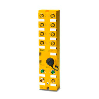
Page 8: Front View
Input module on slot 2 with plug-in connectors X05 and X06 Input module on slot 3 with plug-in connectors X07 and X08 Status LEDs End cap for the microSD card and reset button Status LEDs SafetyNET p interface with plug-in connectors X21 and X22 Operating Manual PSS67 PLC1 16FDI 1004541-EN-03... -
Page 9: Scope Of Supply
Year of manufacture 2D code 11x2.5 mm Scope of supply PSS67 device PSS67 PLC1 16FDI with: – End cap for the microSD card and reset button – 13 label strips – 2 x M4 locking washers for the functional earth –... -
Page 10: Safety
Safety Intended use The PSS67 device PSS67 PLC1 16FDI is suitable for use in a rugged industrial environ- ment up to protection type IP67. It may not be used in a potentially explosive area. The PSS67 device PSS67 PLC1 16FDI is suitable for use in safety-related applications with SafetyNET p and in non-safety-related applications for external communication. -
Page 11: Function Description
Function description Function description The PSS67 device PSS67 PLC1 16FDI consists of a head module of the performance class PSS 4000 PLC with a SafetyNET p interface and four input modules. The head mod- ule and input modules are connected via an internal module bus. The inputs of each mod- ule are implemented on two plug-in connectors. -
Page 12: Head Module
The MAC address is a factory-set default. It can found on the labelling strip on the front of the module. INFORMATION Further information on SafetyNET p can be found in the "PSS 4000 System Description". Operating Manual PSS67 PLC1 16FDI | 12 1004541-EN-03... -
Page 13: External Communication
Files may be damaged if the card is removed from the device or the power to the device is switched off as the SD card is being written. Remove the SD card only in recovery mode or in switched-off state. Operating Manual PSS67 PLC1 16FDI | 13 1004541-EN-03... -
Page 14: Reset Button
The warm reset and the recovery mode and transfer of the naming data and/or device project are described in the "PSS 4000 System Description". This is also where the general effects on the device are described in detail. Operating Manual PSS67 PLC1 16FDI | 14 1004541-EN-03... -
Page 15: Input Modules
Test pulse signals are always buffered for 20 ms. The module provides the following diagnostic data: Start-up error Configuration error FS communication error Bus termination error Temperature error: Too warm Test pulse error Input error Operating Manual PSS67 PLC1 16FDI | 15 1004541-EN-03... -
Page 16: Pssu Assignment In System Environment B
X07 and X08 I2(X08:4) I3(X08:2) 4.3.3 Reaction times Information on the reaction times of the inputs can be found in the "PSSuniversal" System Description and the System Description "Automation system PSS 4000". Operating Manual PSS67 PLC1 16FDI | 16 1004541-EN-03... -
Page 17: Derating Diagram
The relationship between the load current at the load supply and the operating temperature is illustrated in the following derating diagram. The device supply is limited to a maximum of 8 A. T [°C] I [A ] Fig.: Derating diagram for the load supply Operating Manual PSS67 PLC1 16FDI | 17 1004541-EN-03... -
Page 18: Installation
(X0) is 2.5 mm². For the fixing screw you can use the supplied ratchet screw for the functional earth con- nection. Tighten the fixing screw with a torque of 1.2 Nm. Operating Manual PSS67 PLC1 16FDI | 18 1004541-EN-03... -
Page 19: Dimensions
Installation 5.1.1 Dimensions 61.5 Fig.: Dimensions in mm Operating Manual PSS67 PLC1 16FDI | 19 1004541-EN-03... -
Page 20: Wiring
For details of the cable length for the test pulses see Technical details [ 39]. Pilz pre-assembled cable can be used to connect the inputs (see order reference). We recommend you use pre-assembled Pilz connectors to connect the inputs and test pulse outputs (see order reference). -
Page 21: Connector Pin Assignment
L-coded 2: 0 V supply voltage for load supply 3: 0 V supply voltage for device supply 4: + 24 VDC supply voltage for load sup- 5: Connection to functional earth. Operating Manual PSS67 PLC1 16FDI | 21 1004541-EN-03... -
Page 22: Connecting The Supply Voltage
The functional earth can be connected to pin 5 of the X31 connector or to the lower fixing screw (X0). We recommend that you connect the functional earth to the lower fixing screw (X0). Operating Manual PSS67 PLC1 16FDI | 22 1004541-EN-03... - Page 23 Fig.: Separate power supplies for device supply and load supply Infeed for device supply max. 8 A Infeed for load supply max. 16 A Fig.: Common power supply for device supply and load supply Operating Manual PSS67 PLC1 16FDI | 23 1004541-EN-03...
-
Page 24: Wiring Examples
Separate test pulse: Test pulse assignment in PAS4000: – I0: T0 – I1: T1 Pin assignment: – 1: T0 – 2: I1 – 3: 0 V – 4: I0 – 5: T1 Operating Manual PSS67 PLC1 16FDI | 24 1004541-EN-03... -
Page 25: Dual-Channel Homogeneous Safety Switch With Common Test Pulse
Depending on the application, serious injury or death may result. Avoid short circuits through – Appropriate wiring – Wiring in accordance with the requirements of IEC 61076-2-101 and IEC 60204-1, clause 14.1.1 and 14.1.2 Operating Manual PSS67 PLC1 16FDI | 25 1004541-EN-03... -
Page 26: Electronic Safety Switch With Ossd Outputs
Test pulse switched off in PAS4000: – I0: 24 V – I1: 24 V Pin assignment: – 1: 24 V – 2: I1 – 3: 0 V – 4: I0 – 5: 24 V Operating Manual PSS67 PLC1 16FDI | 26 1004541-EN-03... -
Page 27: Operation
PAS4000 or the combination of OPC Server and PSS 4000 Diag Control. Display elements Legend LED on LED flashes LED off 7.2.1 I0 ... I3 (X01 ... X08) Colour State Meaning - - - 0 signal is present Green 1 signal is present Operating Manual PSS67 PLC1 16FDI | 27 1004541-EN-03... -
Page 28: Fs Run
Operating state: "FS resource in RUN condition with error": - Task in TERMINATED condition or - Task in STOP condition At least one FS resource task is not running. The project is unlicensed. Operating Manual PSS67 PLC1 16FDI | 28 1004541-EN-03... -
Page 29: St Run
Operating state: "ST resource in RUN condition with error": - Task in TERMINATED condition or - Task in STOP condition At least one ST resource task is not running. The project is unlicensed. Operating Manual PSS67 PLC1 16FDI | 29 1004541-EN-03... -
Page 30: Diag
(see diagnostic list). Orange A message of at least "Warning" severity is present for the device (see diagnostic list). Red - green Start of "deliberate operator action" (function of reset button) Operating Manual PSS67 PLC1 16FDI | 30 1004541-EN-03... -
Page 31: Fs Force
On the FS resource, forcing is inactive and there is no on- line change active yellow On the FS resource, forcing is active and/or there is at least one online change active Operating Manual PSS67 PLC1 16FDI | 31 1004541-EN-03... -
Page 32: St Force
On the ST resource, forcing is inactive and there is no on- line change active Yellow On the ST resource, forcing is active and/or there is at least one online change active Operating Manual PSS67 PLC1 16FDI | 32 1004541-EN-03... -
Page 33: Fs Snp
Operating status "FS SafetyNET p RTFN in RUN condition with minor error" Operating state "FS SafetyNET p RTFN in STOP condition with error: Major FS error" Operating state "FS SafetyNET p RTFN in STOP condition with error: Major FS+ST error Operating Manual PSS67 PLC1 16FDI | 33 1004541-EN-03... -
Page 34: St Snp
Operating state "ST SafetyNET p RTFN in RUN condition without error" Operating state "ST SafetyNET p RTFN in RUN condition with minor error" Operating state "ST SafetyNET p RTFN in STOP condition with error: Major FS+ST error" Operating Manual PSS67 PLC1 16FDI | 34 1004541-EN-03... -
Page 35: Sd Card
Recovery mode: The file system of the SD card is in a consistent state and the SD card can be removed. Green-red Naming data and device project on the PSSu system and SD card do not match Orange Device identification activated by user Operating Manual PSS67 PLC1 16FDI | 35 1004541-EN-03... -
Page 36: Lnk, Trf (X21, X22)
FS system section (see diagnostic list). At least one message of "Warning" severity is present for the device, no message of "Error" severity is present and no invalid data is being downloaded to the scanner. Operating Manual PSS67 PLC1 16FDI | 36 1004541-EN-03... -
Page 37: Ns/Bf
PROFINET IO modules are configured. green The PROFINET IO Device is in "Operational" state, data exchange possible No connection to PROFINET IO Controller Connection to PROFINET IO Controller avail- able, no data exchange due to faulty parameter settings Operating Manual PSS67 PLC1 16FDI | 37 1004541-EN-03... -
Page 38: 24V (X31, X32)
The "24 V" LED shows the status of the load supply. Colour State Meaning - - - No supply voltage for load supply or supply voltage is faulty Green Load supply connected Operating Manual PSS67 PLC1 16FDI | 38 1004541-EN-03... -
Page 39: Technical Details
+/- 10s/day Buffer time 10 days Max. number of FS tasks Max. number of ST tasks Min. cycle time of FS tasks 6 ms Min. cycle time of ST tasks 2 ms Operating Manual PSS67 PLC1 16FDI | 39 1004541-EN-03... - Page 40 Max. number of ST-Tx and ST-Rx connections Max. number of FS-Tx and FS-Rx connections Cycle time (t_SNp RTFN) 2 ... 60 000 ms PROFINET interface Input device 1.440 Byte Output 1.440 Byte Operating Manual PSS67 PLC1 16FDI | 40 1004541-EN-03...
- Page 41 8,4 - 150 Hz Acceleration 10 m/s² Shock stress In accordance with the standard EN 60068-2-27 Number of shocks Acceleration 150 m/s² Duration 11 ms In accordance with the standard EN 60068-2-27 Operating Manual PSS67 PLC1 16FDI | 41 1004541-EN-03...
- Page 42 1000 V Mechanical data Connection type Mounting type screw interlocked Dimensions Height 260 mm Width 61,5 mm Depth 52 mm Weight 940 g Where standards are undated, the 09-2016 latest editions shall apply. Operating Manual PSS67 PLC1 16FDI | 42 1004541-EN-03...
-
Page 43: Safety Characteristic Data
A safety function's SIL/PL values are not identical to the SIL/PL values of the units that are used and may be different. We recommend that you use the PAScal software tool to calculate the safety function's SIL/PL values. Operating Manual PSS67 PLC1 16FDI | 43 1004541-EN-03... -
Page 44: Order Reference
5 pin, L, S M12 con., straight, male, 5 Connector, M12, 5-pin, L-coded 380318 pin, L, S Crimping Tool Crimping tool for crimping machined con- 380071 tacts. Suitable for cross-sections of 0.08 - 2.5 mm² Operating Manual PSS67 PLC1 16FDI | 44 1004541-EN-03... - Page 45 PSENcode Plug Product type Features Order no. Caps for IP67 modules Protective caps for M12 sockets (4 pieces) 380324 PSS67 Cap 7/8” End cap for the microSD card and reset but- 316011 Operating Manual PSS67 PLC1 16FDI | 45 1004541-EN-03...
-
Page 46: Ec Declaration Of Conformity
European Parliament and of the Council. The complete EC Declaration of Conformity is available on the Internet at www.pilz.com/downloads. Authorised representative: Norbert Fröhlich, Pilz GmbH & Co. KG, Felix-Wankel-Str. 2, 73760 Ostfildern, Germany Operating Manual PSS67 PLC1 16FDI... -
Page 47: Ukca-Declaration Of Conformity
2008. The complete UKCA Declaration of Conformity is available on the Internet at www.pilz.com/ support/downloads. Representative: Pilz Automation Technology, Pilz House, Little Colliers Field, Corby, Northamptonshire, NN18 8TJ United Kingdom, eMail: mail@pilz.co.uk Operating Manual PSS67 PLC1 16FDI | 47... - Page 48 We are represented internationally. Please refer to our homepage www.pilz.com for further details or contact our headquarters. Headquarters: Pilz GmbH & Co. KG, Felix-Wankel-Straße 2, 73760 Ostfildern, Germany Telephone: +49 711 3409-0, Telefax: +49 711 3409-133, E-Mail: info@pilz.com, Internet: www.pilz.com...
Need help?
Do you have a question about the PSS67 PLC1 16FDI and is the answer not in the manual?
Questions and answers