
Subscribe to Our Youtube Channel
Related Manuals for Pilz PSS 3032


Summary of Contents for Pilz PSS 3032
- Page 1 (217) 352-9330 | Click HERE Find the Pilz PSS 3032 at our website:...
- Page 2 PSS 3032 ® Programmable control systems PSS Installation Manual – Item No. 19 891...
- Page 3 All rights to this manual are reserved by the publishers. Copies may be made for internal purposes. In the interests of continual technical advancement we reserve the right to amend specifications without prior notice. No responsibility accepted for errors or omissions. The names of products, goods and technologies used in this manual are trademarks of the companies concerned.
-
Page 4: Table Of Contents
Connecting the earth cables Cabling Equipotential bonding Screened cables Suppression of inductive loads Miscellaneous Installing within an enclosure or wall-mounting Testing the EMC-compatibility of an installation Installation Installing the PSS 3032 Installing the PSS 3032 in a control cabinet Installation Manual: PSS 3032... - Page 5 Example: Dual-channel, failsafe input device, with test pulse 5-12 Single-pole 0.5 A outputs/test pulses 5-14 Configuration 5-15 Dual-pole 2 A outputs 5-16 Configuration 5-17 Interfaces PG programming interface RS 232 user interface Appendix Changes to the Installation Manual Installation Manual: PSS 3032...
-
Page 6: Introduction
Introduction This installation manual contains all the information you need to install a PSS 3032 programmable safety system. It gives safety guidelines which should be followed during installation and also describes the installation procedure and measures which can be taken to ensure EMC compliance. - Page 7 Introduction Notes Installation Manual: PSS 3032...
-
Page 8: Safety Regulations
Safety Regulations To ensure that the PSS 3032 programmable safety system functions correctly, please follow the safety guidelines given below: • Electrical connections should be made by a qualified electrical engineer who is familiar with the information in this manual as well as the relevant regulations concerning health and safety at work. - Page 9 0 V mains earthed at a single point. The connection of the 0 V supply to the central earth bar or earth fault monitor must be in accordance with the relevant national regulations (such as EN 60 204, VDE 0113, NFPA 79-1991:17-7, NEC: Article 250, for example). Installation Manual: PSS 3032...
-
Page 10: Installation
Not permitted Vibration (EN 60 068-2-6, 04/95) Frequency range: 10 ... 100 Hz Amplitude: 0.1 mm, max. 5g Shock (DIN IEC 68-2-29) 30g, 11 ms/10g, 16 ms EN 50 082-2, 03/95 EN 55 011 A, 08/96 Installation Manual: PSS 3032... -
Page 11: Connections
• In extreme ambient conditions, additional measures may be required in order to keep within the prescribed value range (e.g. air-conditioning within the control cabinet). • The PSS 3032 must be installed in such a way that buttons and switches cannot be operated unintentionally. Connections •... -
Page 12: Electromagnetic Compatibility (Emc)
Electromagnetic Compatibility (EMC) Overview The PSS 3032 is designed to be installed within an electromagnetic industrial environment. To ensure electromagnetic compatibility the correct procedures must be carried out when installing the system. A device is electromagnetically compatible if: • It functions without error in a given electromagnetic environment. -
Page 13: Making The Installation Emc-Compatible
Making the installation EMC-compatible Connecting the earth cables PSS safety systems all meet protection class 1 (DIN VDE 0106, Part 1/A1, 04/90). The prescribed earth points are designed for your safety and to guarantee compliance with noise resistance requirements. Installation Manual: PSS 3032... -
Page 14: Cabling
• Lines from group 1 and group 2 should be laid in separate groups or in cable ducts which are at least 10 cm apart. • Lines from group 1 and group 3 should be laid in separate groups or in cable ducts which are at least 50 cm apart. Installation Manual: PSS 3032... -
Page 15: Equipotential Bonding
• Use copper or galvanised steel equipotential bonding cable. • Connect equipotential bonding cables to the earth conductor over as wide a surface area as possible. • As short a distance as possible should be kept between the equipotential bonding cable and signal cable. Installation Manual: PSS 3032... -
Page 16: Screened Cables
Suppression should not be used to protect the semiconductor outputs. Miscellaneous Connecting the programming device The programming device requires a mains connection in each cabinet. The mains connection must be connected to the same distributor as the earth conductor for the cabinet. Installation Manual: PSS 3032... -
Page 17: Installing Within An Enclosure Or Wall-Mounting
• Install an earth bar for the cable screens. • The earth bar can also be used as the ground conductor bar. • Connect the earth bar to the mounting plate over a wide surface area and with low impedance. Installation Manual: PSS 3032... -
Page 18: Testing The Emc-Compatibility Of An Installation
Testing the EMC-compatibility of an installation Use the following list to check that the PSS 3032 has been installed to conform with EMC-regulations. Check Action Done Before installation: Are there areas with a high Make detailed plans for EMC probability of interference? protection in these areas. - Page 19 Are inductive loads Inductive loads not switched by switched? the PSS 3032 must be wired with suppression elements. 24 VDC power supply? The power supply must conform to DIN VDE 0551 / EN 60 742 and DIN VDE 0160.
-
Page 20: Installation
Installation Installing the PSS 3032 There are two ways to install the PSS 3032. Both are shown in Fig. 3-1. Drill 4 x M5 or M6 holes in the mounting plate of the control cabinet as shown in Fig. 3-1 (tolerance: +/-0.3 mm/0.012"). Screw the PSS 3032 to the mounting plate using washers. -
Page 21: Installing The Pss 3032 In A Control Cabinet
I 0.16 I 0.17 I 0.18 I 0.19 No minimum distance from control cabinet required Min. 60 mm (2.36") Power section Fig. 4-2: Installing the PSS 3032 in a control cabinet, dimensions stated in mm (") Installation Manual: PSS 3032... -
Page 22: Connecting The Inputs And Outputs
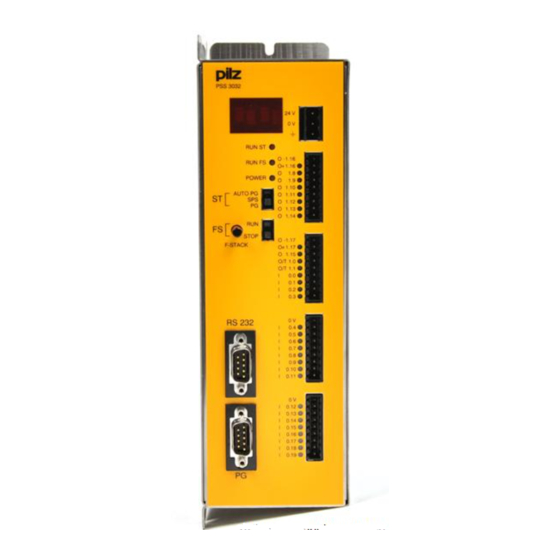
F-Stack O 1.15 O/T 1.0 O/T 1.1 RS 232 I 0.10 I 0.11 0.12 I 0.13 I 0.14 I 0.15 I 0.16 I 0.17 I 0.18 I 0.19 Fig. 5-1: Terminal configuration on the PSS 3032 Installation Manual: PSS 3032... -
Page 23: Notes On Wiring
• In principle, the possibility of earth faults and line breaks occurring cannot be eliminated. If a dual-pole switching output on the PSS 3032 is used to drive the actuators, a test for short circuits and line breaks will automatically be carried out during each cycle. - Page 24 Notes Installation Manual: PSS 3032...
-
Page 25: Digital Inputs
(on switching off) are permitted for safety-related applications. • Signals may be connected using unscreened cables. CAUTION! The connection shown overleaf is only approved for non-safety applications. The connection of safe input devices for safety-relevant applications is described later in the chapter. Installation Manual: PSS 3032... -
Page 26: Configuration
I 0.10 I 0.11 Input I0.12 I 0.12 I 0.13 I 0.14 I 0.15 I 0.16 I 0.17 I 0.18 Input I0.19 I 0.19 24 V DC Please ensure safety regulations and EMC guidelines are observed! Installation Manual: PSS 3032... -
Page 27: Example: Single-Channel, Failsafe Input Device, Unchecked
Depending on the type of input device connected, this could create a risk to both personnel and machinery (e.g. emergency stop). You should always ensure that the unit is suitably wired to eliminate the risk of short circuits. Installation Manual: PSS 3032... - Page 28 O -1.17 O +1.17 O 1.15 O/T 1.0 O/T 1.1 Single-channel, failsafe 0.10 0.11 input device 0.12 0.13 0.14 0.15 0.16 0.17 0.18 0.19 24 V DC Please ensure safety regulations and EMC guidelines are observed! Installation Manual: PSS 3032...
-
Page 29: Example: Dual-Channel Input Devices, Unchecked
• If you are using input devices with different (diverse) channels, adjacent inputs may be used. Short circuits will be detected in the application program via the feasibility check (see example in the Programming Manual). Installation Manual: PSS 3032... - Page 30 I 0.12 channels I 0.13 I 0.14 I 0.15 I 0.16 I 0.17 I 0.18 I 0.19 Dual-channel input device with different (diverse) channels 24 V DC Please ensure safety regulations and EMC guidelines are observed! Installation Manual: PSS 3032...
-
Page 31: Example: Single-Channel, Failsafe Input Device, With Test Pulse
• Short circuits between the cable from the signal to the input device and the cable from the input device to the input will not be detected. • Only input devices with N/C contacts can be tested. 5-10 Installation Manual: PSS 3032... - Page 32 Single-channel, failsafe input device I 0.10 I 0.11 0.12 I 0.13 I 0.14 I 0.15 I 0.16 I 0.17 I 0.18 I 0.19 24 V DC Please ensure safety regulations and EMC guidelines are observed! Installation Manual: PSS 3032 5-11...
-
Page 33: Example: Dual-Channel, Failsafe Input Device, With Test Pulse
• If the input device has only one signal, a short circuit between the cables from the input device to the inputs will not be detected. You should always ensure that the unit is suitably wired to avoid the risk of this type of short circuit. 5-12 Installation Manual: PSS 3032... - Page 34 I 0.13 I 0.14 I 0.15 I 0.16 I 0.17 I 0.18 Dual-channel input device I 0.19 with diverse channels 24 V DC Please ensure safety regulations and EMC guidelines are observed! Installation Manual: PSS 3032 5-13...
-
Page 35: Single-Pole 0.5 A Outputs/Test Pulses
Outputs are designed for resistive and inductive loads. • All outputs have a common second shutdown route. This means that the PSS 3032 can be used for single-channel operation in applications conforming to EN 954-1 (11/94), up to safety category 3. Please note... -
Page 36: Configuration
I 0.14 I 0.14 I 0.15 I 0.15 I 0.16 I 0.16 I 0.17 I 0.17 I 0.18 I 0.18 I 0.19 I 0.19 24 V DC Please ensure safety regulations and EMC guidelines are observed! Installation Manual: PSS 3032 5-15... -
Page 37: Dual-Pole 2 A Outputs
• 2 dual-pole outputs, O1.16 and O1.17 • The outputs are dual-pole switching 2 A outputs. • The PSS 3032 operating system tests the outputs during each cycle. Any short circuits or open circuits to the load will be detected. -
Page 38: Configuration
O +1.17 O 1.15 O/T 1.0 O/T 1.1 I 0.10 I 0.11 0.12 I 0.13 I 0.14 I 0.15 I 0.16 I 0.17 I 0.18 I 0.19 Please ensure safety regulations and EMC guidelines are observed! Installation Manual: PSS 3032 5-17... - Page 39 Connecting the Inputs and Outputs Notes 5-18 Installation Manual: PSS 3032...
-
Page 40: Interfaces
A detailed description of the interface can be found in the “FS System Description” and “ST System Description” which form part of the “PSS-Range System Manual”. N. C. N. C. N.C. = no connection Fig. 6-2: Configuration of the user interface Installation Manual: PSS 3032... - Page 41 Interfaces Notes Installation Manual: PSS 3032...
-
Page 42: Appendix
75° C is no longer specified. Changes from version V to version VI Change page page 5-14 5-14 Do not use the test pulse outputs to drive a load to L+. 5-14 5-14 Warning: Exemple inserted Installation Manual: PSS 3032... - Page 43 Appendix Notes Installation Manual: PSS 3032...
- Page 44 • Technical Please refer to our homepage for further details or contact our support headquarters. +49 711 3409-444 Pilz GmbH & Co. KG Sichere Automation Felix-Wankel-Straße 2 73760 Ostfi ldern, Germany Telephone: +49 711 3409-0 Telefax: +49 711 3409-133 E-Mail:...
Need help?
Do you have a question about the PSS 3032 and is the answer not in the manual?
Questions and answers