Table of Contents
Advertisement
Advertisement
Table of Contents

Related Manuals for Pilz PNOZmulti Series


Summary of Contents for Pilz PNOZmulti Series
- Page 1 PNOZ mc7p Configurable Control System PNOZmulti Operating Manual1003050EN02...
- Page 2 Preface This document is the original document. All rights to this documentation are reserved by Pilz GmbH & Co. KG. Copies may be made for internal purposes. Suggestions and comments for improving this documentation will be gratefully received. Pilz®, PIT®, PMI®, PNOZ®, Primo®, PSEN®, PSS®, PVIS®, SafetyBUS p®, SafetyEYE®, SafetyNET p®, the spirit of safety® are registered and protected trademarks of Pilz GmbH & Co. KG in some countries. SD means Secure Digital...
-
Page 3: Table Of Contents
Content Section 1 Introduction Validity of documentation Using the documentation Definition of symbols Section 2 Overview Scope of delivery Unit features Front view Section 3 Safety Intended use System requirements Safety regulations 3.3.1 Use of qualified personnel 3.3.2 Warranty and liability 3.3.3 Disposal 3.3.4 For your safety Section 4 Function description Functions Input and output data Block diagram Section 5 Installation General installation guidelines Dimensions Connecting the base unit and expansion modules Section 6 Commissioning General wiring guidelines Interface assignment Download modified project to the PNOZmulti safety system Connection example Section 7 Operation Messages... -
Page 4: Operating Manual Pnoz Mc7P
Introduction Introduction Validity of documentation This documentation is valid for the product PNOZ mc7p. It is valid until new documentation is published. This operating manual explains the function and operation, describes the installation and provides guidelines on how to connect the product. Using the documentation This document is intended for instruction. Only install and commission the product if you have read and understood this document. The document should be retained for future ref erence. Definition of symbols Information that is particularly important is identified as follows: DANGER! This warning must be heeded! It warns of a hazardous situation that poses an immediate threat of serious injury and death and indicates preventive measures that can be taken. WARNING! This warning must be heeded! It warns of a hazardous situation that could lead to serious injury and death and indicates preventive measures that can be taken. CAUTION! This refers to a hazard that can lead to a less serious or minor injury plus material damage, and also provides information on preventive measures that can be taken. NOTICE This describes a situation in which the product or devices could be dam aged and also provides information on preventive measures that can be taken. It also highlights areas within the text that are of particular import ance. Operating Manual PNOZ mc7p 1003050EN02... - Page 5 Introduction INFORMATION This gives advice on applications and provides information on special fea tures. Operating Manual PNOZ mc7p 1003050EN02...
-
Page 6: Overview
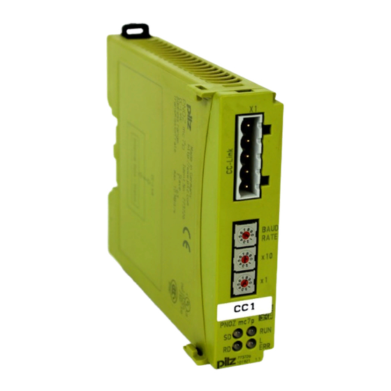
Overview Overview Scope of delivery Expansion module PNOZ mc7p Jumper 774 639 Unit features Using the product PNOZ mc7p: Expansion module for connection to a base unit from the configurable control system PNOZmulti The product has the following features: Can be configured in the PNOZmulti Configurator Connection for CCLink Station addresses from 0 ... 63, selected via rotary switch Station type: Remote Device Occupied stations: 2 24 virtual inputs and outputs on the control system PNOZmulti can be defined in the PNOZmulti Configurator for communication with the fieldbus CCLink . The number of inputs and outputs can be extended to 128. Please note that when the extended inputs and outputs 24 127 are used they have different properties (see document entitled "Communication Interfaces"). Max. 1 PNOZ mc7p can be connected to the base unit Please refer to the document "PNOZmulti System Expansion" for the PNOZmulti base units that can be connected. Front view Operating Manual PNOZ mc7p 1003050EN02... - Page 7 Overview Legend: LED: – – – – L Err Operating Manual PNOZ mc7p 1003050EN02...
-
Page 8: Safety
Safety Safety Intended use The fieldbus module PNOZ mc7p is an expansion module of the configurable control sys tem PNOZmulti. It is used for communication between the configurable control system PNOZmulti and the CCLink . CCLink is designed for fast data exchange at field level. The expansion module CCLink is a passive subscriber (Slave) in CCLink. The basic communication functions with CCLink conform to CCLink V1.10. The central controller (master) reads input information from the slaves and writes output information to the slaves as part of each cycle. As well as the cyc lical transfer of usable data, the expansion module PNOZ mc7p also has diagnostic and commissioning functions. Data traffic is monitored on the Master/Slave side. The expansion module may only be connected to a base unit from the configurable control system PNOZmulti (please refer to the document "PNOZmulti System Expansion" for de tails of the base units that can be connected) The configurable control system PNOZmulti is used for the safetyrelated interruption of safety circuits and is designed for use in: ESTOP equipment Safety circuits in accordance with VDE 0113 Part 1 and EN 602041 The expansion module may not be used for safetyrelated functions. The following is deemed improper use in particular: Any component, technical or electrical modification to the product Use of the product outside the areas described in this manual Use of the product outside the technical details (see chapter entitled "Technical De tails"). NOTICE EMCcompliant electrical installation The product is designed for use in an industrial environment. The product may cause interference if installed in other environments. If installed in other environments, measures should be taken to comply with the applicable standards and directives for the respective installation site with regard to in terference. System requirements Please refer to the "Product Modifications" document in the "Version overview" section for details of which versions of the base unit and PNOZmulti Configurator can be used for this product. Operating Manual PNOZ mc7p 1003050EN02... -
Page 9: Safety Regulations
Safety Safety regulations 3.3.1 Use of qualified personnel The products may only be assembled, installed, programmed, commissioned, operated, maintained and decommissioned by competent persons. A competent person is someone who, because of their training, experience and current pro fessional activity, has the specialist knowledge required to test, assess and operate the work equipment, devices, systems, plant and machinery in accordance with the general standards and guidelines for safety technology. It is the company’s responsibility only to employ personnel who: Are familiar with the basic regulations concerning health and safety / accident preven tion Have read and understood the information provided in this description under "Safety" And have a good knowledge of the generic and specialist standards applicable to the specific application. 3.3.2 Warranty and liability All claims to warranty and liability will be rendered invalid if The product was used contrary to the purpose for which it is intended Damage can be attributed to not having followed the guidelines in the manual Operating personnel are not suitably qualified Any type of modification has been made (e.g. exchanging components on the PCB boards, soldering work etc.). 3.3.3 Disposal When decommissioning, please comply with local regulations regarding the disposal of electronic devices (e.g. Electrical and Electronic Equipment Act). 3.3.4 For your safety The unit meets all the necessary conditions for safe operation. However, you should always ensure that the following safety requirements are met: This operating manual only describes the basic functions of the unit. The expanded functions are described in the PNOZmulti Configurator's online help. Only use these functions once you have read and understood the documentations. Do not open the housing or make any unauthorised modifications. Please make sure you shut down the supply voltage when performing maintenance work (e.g. exchanging contactors). Operating Manual PNOZ mc7p 1003050EN02... -
Page 10: Function Description
Function description Function description Functions The virtual inputs and outputs that are to be transferred via the fieldbus CCLink are selec ted and configured in the PNOZmulti Configurator. The base unit and the fieldbus module PNOZ mc7p are connected via a jumper. The fieldbus module is also supplied with voltage via this jumper. After the supply voltage is switched on or the control system PNOZmulti is reset, the fieldbus module PNOZ mc7p is configured and started automatically. LEDs indicate the status of the fieldbus module on the fieldbus CCLink . The configuration is described in detail in the PNOZmulti Configurator's online help. Input and output data The data is structured as follows: Input area – Inputs on PNOZmulti Configurator: i00 … i23 – Input data CCLink: RYn, RY1n with n = 0 … F Example: i23 > RY17 RY0n i15 i14 i13 i12 i11 i10 i09 i08 i07 i06 i05 i04 i03 i02 i01 i00 RY1n ... -
Page 11: Block Diagram
Function description Block diagram FG/PE Operating Manual PNOZ mc7p 1003050EN02... -
Page 12: Installation
Installation Installation General installation guidelines The control system should be installed in a control cabinet with a protection type of at least IP54. Fit the control system to a horizontal mounting rail. The venting slots must face upward and downward. Other mounting positions could destroy the control system. Use the notches on the rear of the unit to attach it to a mounting rail. Connect the con trol system to the mounting rail in an upright position, so that the earthing springs on the control system are pressed on to the mounting rail. The ambient temperature of the PNOZmulti units in the control cabinet must not exceed the figure stated in the technical details, otherwise air conditioning will be required. To comply with EMC requirements, the mounting rail must have a low impedance con nection to the control cabinet housing. CAUTION! Damage due to electrostatic discharge! Electrostatic discharge can damage components. Ensure against discharge before touching the product, e.g. by touching an earthed, conductive sur face or by wearing an earthed armband. Dimensions 22,5 94 (3.70") (0.88") Connecting the base unit and expansion modules You can install a maximum of 1 PNOZ mc7p to the left of the base unit. Do not connect a terminator to the last expansion module on the lefthand side. Install the expansion module in the position in which it is configured in the PNOZmulti Configurator. Operating Manual PNOZ mc7p 1003050EN02... -
Page 13: Commissioning
Commissioning Commissioning General wiring guidelines The wiring is defined in the circuit diagram of the PNOZmulti Configurator. Please note: Information given in the "Technical details" must be followed. Use copper wiring with a temperature stability of 75°C. Always connect the mounting rail to the protective earth via an earthing terminal. This will be used to dissipate hazardous voltages in the case of a fault. The power supply must meet the regulations for extra low voltages with protective sep aration. CAUTION! Only connect and disconnect the expansion module when the supply voltage is switched off. NOTICE When installing, you must refer to the guidelines of the CANopenUser Group. Interface assignment It is possible to define which outputs on the safety system will communicate with CCLink. The connection to CCLink is made via a 5pin screw connector. FG/PE DB DG SLD 1: DA (Channel A) 2: DB (Channel B) 3: DG (Earth) 4: SLD (Cable shield) 5: FG/PE (Functional earth) Operating Manual PNOZ mc7p 1003050EN02... -
Page 14: Download Modified Project To The Pnozmulti Safety System
Commissioning Download modified project to the PNOZmulti safety system As soon as an additional expansion module has been connected to the system, the project must be amended using the PNOZmulti Configurator. Proceed as described in the operat ing instructions for the base unit. NOTICE For the commissioning and after every program change, you must check whether the safety devices are functioning correctly. Connection example CC-Link CC-Link Slave n CC-Link Slave 1 Slave 3 CC-Link Master PNOZ mc7p CC-Link BAUD RATE CC-Link PNOZ mc7p Slave 2 ERR. Operating Manual PNOZ mc7p 1003050EN02... -
Page 15: Operation
Operation Operation When the supply voltage is switched on, the PNOZmulti safety system copies the configur ation from the chip card. The LEDs “POWER”, “DIAG”, “FAULT”, “IFAULT” and “OFAULT” will light up on the base unit. The expansion module PNOZ mc7p is configured and started automatically. Messages Legend: LED on LED off Meaning Green Bus connection available Bus connection is not available Status: timeout No supply voltage at the fieldbus module PNOZ mc7p L Err Fault detected: Wrong station address or transmission rate Flashes evenly: setting has been changed during operation and PNOZ mc7p has not been restarted Flashes unevenly: faulty connection, e.g. terminating resistor is missing Bus connection available No supply voltage at the fieldbus module PNOZ mc7p Green PNOZ mc7p Receiving data PNOZ mc7p Not receiving data No supply voltage at the fieldbus module PNOZ mc7p Green PNOZ mc7p Sending data PNOZ mc7p Not sending data No supply voltage at the fieldbus module PNOZ mc7p Operating Manual PNOZ mc7p 1003050EN02... -
Page 16: Technical Details
Technical Details Technical Details General Approvals CCC, CE, GOST, cULus Listed Electrical data Supply voltage Module supply Voltage 5,0 V Kind Voltage tolerance 2 %/+2 % Power consumption 2,5 W Status indicator Fieldbus interface Fieldbus interface CCLink V1.10 Unit type Slave Station address 0 ... 63d Transmission rates 10 MBit/s, 156 kbit/s, 2,5 MBit/s, 5 MBit/s, 625 kbit/ Connection 5pin Combicon plugin connector Assigned stations Galvanic isolation Test voltage 500 V AC Times Supply interruption before deenergisation 20 ms Environmental data Ambient temperature In accordance with the standard EN 60068214 Temperature range 0 60 °C Storage temperature In accordance with the standard EN 6006821/2... - Page 17 Technical Details Environmental data Airgap creepage In accordance with the standard EN 611312 Overvoltage category Pollution degree Rated insulation voltage 30 V Protection type In accordance with the standard EN 60529 Mounting area (e.g. control cabinet) IP54 Housing IP20 Terminals IP20 Potential isolation Potential isolation between Fieldbus and module voltage Type of potential isolation Functional insulation Rated surge voltage 500 V Mechanical data Mounting position Horizontal on top hat rail DIN rail Top hat rail 35 x 7,5 EN 50022 Recess width 27 mm Material Bottom PPO UL 94 V0 Front ABS UL 94 V0 Dimensions Height 94,0 mm Width 22,5 mm...
-
Page 18: Order Reference
Order reference Order reference Product Product type Features Order no. PNOZ mc7p Fieldbus module, CCLink 773 716 Accessories Product type Features Order no. PNOZmulti bus terminator Terminator 779 110 KOPXE Jumper 774 639 Operating Manual PNOZ mc7p 1003050EN02... - Page 19 Back cover Support Technical support is available from Pilz round the clock. Americas Australia Scandinavia Brazil +61 3 95446300 +45 74436332 +55 11 97569-2804 Spain Canada Europe +34 938497433 Switzerland +1 888-315-PILZ (315-7459) Austria +43 1 7986263-0 +41 62 88979-30 Mexico...
Need help?
Do you have a question about the PNOZmulti Series and is the answer not in the manual?
Questions and answers