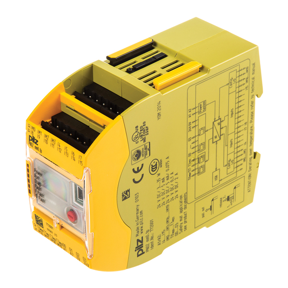
Pilz PNOZmulti Mini Operating Manual

Pilz PNOZmulti Mini Operating Manual

Configurable compact control systems
Hide thumbs Also See for PNOZmulti Mini:

Advertisement

Quick Links

PNOZ mm0p-T
}
Configurable compact control systems PNOZmulti Mini
Operating Manual 1002704-EN-02

Advertisement

Table of Contents
loading

Summary of Contents for Pilz PNOZmulti Mini

  • Page 1 PNOZ mm0p-T Configurable compact control systems PNOZmulti Mini Operating Manual 1002704-EN-02...
  • Page 2 Preface This document is a translation of the original document. All rights to this documentation are reserved by Pilz GmbH & Co. KG. Copies may be made for internal purposes. Suggestions and comments for improving this documentation will be gratefully received.
  • Page 3: Table Of Contents

    Contents Section 1 Introduction Validity of documentation Using the documentation Definition of symbols Section 2 Overview Range Unit features Chip card Front view Section 3 Safety Intended use System requirements Safety regulations 3.3.1 Safety assessment 3.3.2 Use of qualified personnel 3.3.3 Warranty and liability 3.3.4...
  • Page 4 Contents Section 7 Operation LED indicators Restart PNOZmulti Stop PNOZmulti Section 8 Technical details Safety characteristic data Section 9 Supplementary data Maximum capacitive load C (μF) with load current I (A) at the semicon- ductor outputs Maximum permitted total current of the semiconductor outputs Section 10 Order reference Operating Manual PNOZ mm0p-T...
  • Page 5: Operating Manual Pnoz Mm0P-T

    Introduction Introduction Validity of documentation This documentation is valid for the product PNOZ mm0p-T. It is valid until new documenta- tion is published. This operating manual explains the function and operation, describes the installation and provides guidelines on how to connect the product. Using the documentation This document is intended for instruction.
  • Page 6 Introduction INFORMATION This gives advice on applications and provides information on special fea- tures. Operating Manual PNOZ mm0p-T 1002704-EN-02...
  • Page 7: Overview

    Overview Overview Range Base unit PNOZ mm0p-T Right-hand terminator: (yellow) Left-hand terminator: (yellow/black) Unit features Using the product PNOZ mm0p-T: Base unit from the configurable control system PNOZmulti The product has the following features: Can be configured in the PNOZmulti Configurator Semiconductor outputs: 4 safety outputs Depending on the application, up to PL e of EN ISO 13849-1 and up to SIL CL 3 of EN...
  • Page 8: Chip Card

    Overview LED for: – Error messages – Diagnostics – Supply voltage – State of the inputs – State of the outputs Test pulse outputs used to monitor shorts across the inputs Monitoring of shorts between the safety outputs Plug-in connection terminals: Either spring-loaded terminal or screw terminal available as an accessory (see order reference) Pushbutton to change the operating status and download the project.
  • Page 9 Overview Legend – Inputs I8 ... I15 – Configurable test pulse/auxiliary outputs T0M20 ... T3M23 – Semiconductor outputs O0 ... O3 – Configurable inputs/outputs IM0 – IM3 – Inputs I4 ... I7 – Configurable inputs/outputs IM16 – IM19 – Supply connections LEDs: –...
  • Page 10: Safety

    Safety Safety Intended use The configurable small control systems PNOZmulti are used for the safety-related interrup- tion of safety circuits and are designed for use in: E-STOP equipment Safety circuits in accordance with VDE 0113 Part 1 and EN 60204-1 CAUTION! Inputs and outputs for standard functions must not be used for safety-re- lated applications.
  • Page 11: Use Of Qualified Personnel

    Safety 3.3.2 Use of qualified personnel The products may only be assembled, installed, programmed, commissioned, operated, maintained and decommissioned by competent persons. A competent person is someone who, because of their training, experience and current pro- fessional activity, has the specialist knowledge required to test, assess and operate the work equipment, devices, systems, plant and machinery in accordance with the general standards and guidelines for safety technology.
  • Page 12: Function Description

    Function description Function description Integrated protection mechanisms The relay conforms to the following safety criteria: The circuit is redundant with built-in self-monitoring. The safety function remains effective in the case of a component failure. The safety outputs are tested periodically using a disconnection test. Functions The function of the safety system's inputs and outputs depends on the safety circuit created using the PNOZmulti Configurator.
  • Page 13: Installation

    Installation Installation Control cabinet installation The unit should be installed in a control cabinet with a protection type of at least IP54. Fit the safety system to a horizontal mounting rail. The venting slots must face upwards and downwards. Other mounting positions could destroy the safety system. Use the notch on the rear of the unit to attach it to a mounting rail.
  • Page 14: Mounting Distances

    Installation 5.1.1 Mounting distances With control cabinet installation it is essential to maintain a certain distance from the top and bottom, as well as to other heat-producing devices (see diagram). The values stated for the mounting distances are minimum specifications. The ambient temperature of the product in the control cabinet must not exceed the figure stated in the technical details, otherwise air conditioning will be required.
  • Page 15: Dimensions

    Installation Dimensions *with spring-loaded terminals 98 (3.86") * 100 (3,94") (1.77") Install base unit without expansion module Make sure that the terminators are inserted on the top left and right of the unit : Left: Black/yellow terminator Right: Yellow terminator Left: Right: Black/yellow...
  • Page 16: Connecting The Base Unit And Expansion Modules

    Installation Connecting the base unit and expansion modules The position of the expansion modules is defined in the PNOZmulti Configurator. The ex- pansion modules are connected to the left or right of the base unit, depending on the type. Please refer to the document "PNOZmulti System Expansion" for details of the number of modules that can be connected to the base unit and the module types.
  • Page 17: Commissioning

    Commissioning Commissioning General wiring guidelines The wiring is defined in the circuit diagram in the Configurator. There you can select the in- puts that are to perform a safety function and the outputs that are to switch this safety func- tion.
  • Page 18: Commissioning The Pnozmulti Safety System

    Commissioning NOTICE Switch off the product before inserting or exchanging the chip card. Make sure that you do not bend the chip card as you insert it into the chip card slot. 6.2.3 Commissioning the PNOZmulti safety system Procedure: Wire the inputs and outputs on the base unit in accordance with the circuit diagram. Connect the supply voltage: –...
  • Page 19: Load Project Via Usb Port

    Commissioning 6.2.3.2 Load project via USB port Procedure: Insert a chip card into the card slot on the base unit. Connect the computer containing the PNOZmulti Configurator to the base unit via the USB port. Switch on the supply voltage. Download the project (see PNOZmulti Configurator's online help).
  • Page 20 Commissioning Redundant output O0 (O2) O1 (O3) Single output O0 (O2) O1 ( O3) Single output with advanced fault O0 (O2) detection* *Two loads may be connected to each safety output with advanced fault detection, even on applications in accordance with EN IEC 62061, SIL CL 3. Prerequisite: Feedback loop is connected, shorts across contacts and external power sources are excluded (e.g.
  • Page 21: Connection Example

    Commissioning Connection example Dual-channel E-STOP and safety gate wiring, monitored start (IM18), feedback loop (IM16) Operating Manual PNOZ mm0p-T 1002704-EN-02...
  • Page 22: Operation

    Operation Operation LED indicators The PNOZmulti control system is ready for operation when the "POWER" and "RUN" LEDs on the base unit are lit continuously. Legend LED on LED flashes LED off Basis Error The existing user program has been deleted. External error on the base unit, leading to a safe condi- tion, e.g.
  • Page 23: Stop Pnozmulti

    Operation Stop PNOZmulti The unit is in a RUN condition. Procedure for stopping the unit: Press the pushbutton for between 4 and 8 seconds to stop the unit. Release the push- button while the INFO LED flashes rapidly. Operating Manual PNOZ mm0p-T 1002704-EN-02...
  • Page 24: Technical Details

    Technical details Technical details General Approvals BG, CCC, CE, EAC (Eurasian), TÜV, cULus Listed Electrical data Supply voltage Supply to the system Voltage 24,0 V Kind Voltage tolerance -15 %/+20 % Output of external power supply (DC) 35,0 W Output of external power supply (DC) at no load 8,0 W Residual ripple DC Supply voltage...
  • Page 25 Technical details Inputs Input voltage in accordance with EN 61131-2 Type 1 24 V DC Input current at rated voltage 5 mA Input current range 2,5 - 5,3 mA Min. pulse duration 16 ms Pulse suppression 0,6 ms Maximum input delay 4 ms Potential isolation Semiconductor outputs...
  • Page 26 Technical details Environmental data Climatic suitability In accordance with the standard EN 60068-2-30, EN 60068-2-78 Humidity 93 % r. h. at 40 °C Condensation during operation Short-term (only with separated extra low voltage) EN 61131-2 Vibration In accordance with the standard EN 60068-2-6 Frequency 10,0 - 150,0 Hz...
  • Page 27: Safety Characteristic Data

    Technical details Mechanical data Material Bottom Front 1 core flexible 0,25 - 2,50 mm², 24 - 12 AWG 2 core with the same cross section, flexible without crimp connectors or with TWIN crimp connectors 0,20 - 1,50 mm², 24 - 16 AWG Torque setting with screw terminals 0,50 Nm Connection type...
  • Page 28 Technical details Output SC outputs 1-channel with ad- vanced fault detection PL e Cat. 4 SIL CL 3 7,65E-10 SC outputs 1-channel PL d Cat. 2 SIL CL 2 8,90E-10 SC outputs 2-channel PL e Cat. 4 SIL CL 3 7,86E-10 All the units used within a safety function must be considered when calculating the safety characteristic data.
  • Page 29: Supplementary Data

    Supplementary data Supplementary data Maximum capacitive load C (μF) with load current I (A) at the semiconductor outputs C [µF] I [A] Maximum permitted total current of the semiconductor outputs [mA] : Total current of the configurable semiconductor outputs (auxiliary outputs) : Total current: Semiconductor outputs (safety outputs) Operating Manual PNOZ mm0p-T 1002704-EN-02...
  • Page 30: Order Reference

    Order reference Order reference Order reference Product type Features Order no. PNOZ mm0p-T Base unit 772 010 Terminals Product type Features Order no. PNOZ s Set1 spring 1 set of spring-loaded terminals 751 008 loaded terminals PNOZ s Set1 screw ter- 1 set of screw terminals 750 008 minals...
  • Page 31 Front cover Support Technical support is available from Pilz round the clock. Americas Australia Scandinavia Brazil +61 3 95446300 +45 74436332 +55 11 97569-2804 Spain Canada Europe +34 938497433 +1 888-315-PILZ (315-7459) Austria Switzerland Mexico +43 1 7986263-0 +41 62 88979-30...

This manual is also suitable for:

Pnoz mm0p-t772 010751 008750 008

Table of Contents