
Subscribe to Our Youtube Channel
Related Manuals for ASCOM teleCARE IP

Summary of Contents for ASCOM teleCARE IP
- Page 1 TD 93021US Installation Guide teleCARE IP Emergency Call System 17 July 2017 / Ver. PF3...
- Page 2 Use this product only in accordance with the purposes for which it is designed. For the latest version of all Ascom teleC- ARE documentation, contact your local supplier or visit the Ascom Partner Website at https:// www.ascom-ws.com.
- Page 3 Installation Guide teleCARE IP TD 93021US Regulatory Compliance Safety Compliance: The equipment described herein complies with: (US/CAN) ANSI/UL 2560 Emergency Call Systems for Assisted Living and Independent Living Facilities Copyright CAN/CSA C22.2 No. 205 Signal Equipment Note: This equipment has been tested and found to comply with the limits for a Class B digital device, pursuant to Part 15 of the FCC Rules.
-
Page 4: Table Of Contents
2 Practical Engineering Parameters ....................4 2.1 General Limitations .........................4 2.2 Network Expectations ......................4 2.3 VoIP Requirements (Supplementary) ..................5 2.4 teleCARE IP Compatible Ascom Handsets (Supplementary) ............5 3 System LAN Cabling ........................6 3.1 Ethernet Switch ........................6 3.2 Ethernet LAN and Room Bus Cables ..................7 4 System Power ..........................10... -
Page 5: Table Of Contents
7.8 Room Display (NIRD) ......................122 8 Wireless Functionality ......................125 8.1 General ..........................125 8.2 Principle of the teleCARE IP with Wireless Functionality ............126 8.3 teleCARE Wireless with Speech ...................128 8.4 teleCARE IP Wireless Planning .....................131 8.5 teleCARE IP Wireless Components ..................137 9 Installation Examples .......................159... -
Page 6: Introduction
Only original teleCARE IP parts and components are to be used in any teleCARE IP installation. In order for the system to function properly these parts must be installed in accordance with the appropriate teleCARE IP installation instructions. -
Page 7: Telecare Ip With Speech
(anesthetic) gases are used. teleCARE IP With Speech The basic installation for a teleCARE IP system with speech is the same as for teleCARE IP without speech with the exception that room controllers with speech support and a supplementary VoIP gateway are required. - Page 8 The Innovaphone VoIP gateway is an IP based gateway providing the VoIP based solution which supports all the features of a traditional PBX. For the teleCARE IP VoIP the SIP Trunk must be used for the interface to the main PBX. The SIP trunk must be set to “Early offer”.For more information refer to the teleCARE IP Configuration Manual TD 93019US.
-
Page 9: Practical Engineering Parameters
TD 93021US Practical Engineering Parameters In order to ensure the optimal performance of a teleCARE IP system it is important to consider certain parameters and limitations. The following tables show the most important practical values which can have an influence on the teleCARE IP system performance. -
Page 10: Voip Requirements (Supplementary)
TD 93021US VoIP Requirements (Supplementary) VoIP Considerations The Innovaphone VoIP gateway version 10 (or later) is required for teleCARE IP with speech, as the interface to the PBX. An interoperability test between the VoIP gateway and main PBX must be performed. -
Page 11: System Lan Cabling
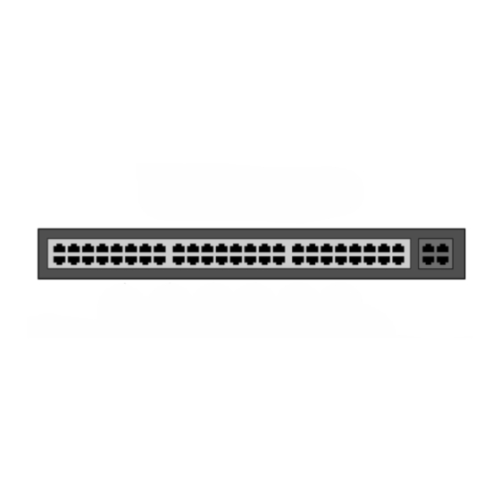
TD 93021US System LAN Cabling Ethernet Switch The 8-port Ethernet Switch, Ascom part number APS5001, shall be used with the teleCARE IP system and can be purchased through Ascom. WARNING: Use of any Ethernet Switch other than Ascom part number APS5001 violates the UL 2560 listing. -
Page 12: Ethernet Lan And Room Bus Cables
Ethernet LAN and Room Bus Cables High quality cables must be used to install the teleCARE IP system. The individual wire cores of the cables should be color coded. Care should be taken when stripping cables from the outer mantle to avoid damaging the insulation of the wire cores. - Page 13 3.2.2 Room Bus Cable The room bus cable connects the room controller to the associated teleCARE IP peripherals. It consists of four wires which carry 5.5 volts, Data, Voice and Ground. The recommended cable for the room bus is TIA/IEA 568-A Category 5 or higher. It is also acceptable to use 2 x twisted pairs of solid copper wires each 20 AWG (0.8mm).
- Page 14 Installation Guide teleCARE IP TD 93021US When UTP category 5 cable (or higher) is used the length of any room bus cable should not exceed 98.4ft (30m), irrespective of the load. Below 98.4ft (30m), the maximum acceptable length of the room bus cable depends on the load.
-
Page 15: System Power
There is a built-in charger to charge sealed lead acid batteries. The batteries provide the Secondary Power to the teleCARE IP system in the event of mains AC power failure. There is an automatic switchover to the batteries when input AC power fails. During switchover, there is zero voltage drop at the power output. - Page 16 4.1.2 Power Supply (Standard) Operation and Maintenance The teleCARE IP Standard Power Supply should be tested at least once a year for proper operation. Under normal load conditions, the DC output voltage should be checked for proper voltage level, which is 24Vdc for the teleCARE IP system.
-
Page 17: Vdc / 8 Amp Power Supply (Seismic)
There is a built-in charger to charge sealed lead acid batteries. The batteries shall provide Secondary Power to the teleCARE IP system in the event of mains AC power failure. There is an automatic switchover to the batteries when input AC power fails. During switchover, there is zero voltage drop at the power output. - Page 18 Line (EOL) resistor for the teleCARE IP system power bus. Before connecting and powering the teleCARE IP system, refer to sections 4.4 and 4.5 in this manual. Install the EOL resistor at the last NIRC3 unit on the teleCARE IP power bus.
- Page 19 Installation Guide teleCARE IP TD 93021US Caution: Connect the negative (-) lead of the teleCARE IP System to the 4L1 terminal and the positive (+) lead to the 4L2 terminal. Re-energize the power supply. 4.2.2 Power Supply (Seismic) Operation and Maintenance The HPFF8 Power Supply should be tested at least once a year for proper operation.
- Page 20 SIG4 through SIG1 output circuits. If all four SIG TRBL LEDs are illuminated steady, check if the Reference Resistor is missing or doesn’t match the EOL resistor used to terminate the teleCARE IP Power Bus. Otherwise, each power circuit probably has a problem.
-
Page 21: Secondary Power
Board or, power cycle the HPFF8 OFF/ON. Secondary Power Secondary Power for the teleCARE IP system shall be provided by two lead acid Batteries installed in the primary power supply. The batteries are each rated for 12Vdc, 7 ampere hours (AH) and can be purchased through an electrical supplier such as Graybar. -
Page 22: Power Supply Unit (24Vdc) With Multiple Power Buses
Installation Guide teleCARE IP TD 93021US Power Supply Unit (24Vdc) with Multiple Power Buses The output of the power supply unit can be divided over multiple buses. This method is recommended as it will reduce the power cable lengths. Figure 6. Multiple power buses 4.5.1 Power Supply Basic Installation... -
Page 23: Maintenance And Service
Other than battery replacements and Secondary Power testing at the power supply unit, periodic maintenance is typically not needed for the teleCARE IP Emergency Call System. • Always keep and refer to the installation and service instructions provided with the Ethernet Switch and the 24Vdc / 3 Amp Power Supply (Standard) or the 24Vdc / 8 Amp Power Supply (Seismic.) -
Page 24: Control Equipment
“System Manager (NISM2)” (details on page 51) Preparation It is important to refer to the following teleCARE IP control module installation instructions for complete electrical connection and assembly details before starting the installation. The Ingress Protection of the control modules is IP40, therefore the areas in which the teleCARE equipment is to be installed must be clean, dry, and weatherproof. - Page 25 5. The NIRC3 can accommodate 4 LED Lamp Boards (NILD2s), enabling the NIRC3 to be used as a corridor lamp. The NIRC3 also has the provisions to provide 24Vdc power for up to two teleCARE IP Corridor Lamps (NICL2s).
- Page 26 Installation Guide teleCARE IP TD 93021US 5.2.2 NIRC3 Parts The NIRC3 includes a housing, a translucent dome cover, and a printed circuit board which has four connectors for LED boards. The LED board (must be ordered separately) is available in five colors: red, green, yellow, white, and blue.
- Page 27 Installation Guide teleCARE IP TD 93021US 5.2.4 Installing the Room Controller When installing the Room Controller the first step is to separate the top section (cover, PC board, and lamp dome) from the housing. To do that simply grip the top edge of the cover and pull it away from the housing, as shown in the following illustration: Figure 14.
- Page 28 Installation Guide teleCARE IP TD 93021US 5.2.6 Room Controller Housing The room controller housing is designed to be surface mounted. It can be mounted over a back box or fixed directly on to a wall surface. The same housing is used for the IP room controller with LED lamps and with blank cover and for the corridor lamp.
- Page 29 Installation Guide teleCARE IP TD 93021US Make sure the long sides are horizontal, then tighten the back box fixing screws to secure the housing. Figure 18. Fixing the housing 5.2.8 Mounting the Housing without a Back box The housing can be mounted on a flat surface, without a back box, using four suitable screws in the outer fixing holes, as shown in the illustration below.
-
Page 30: Preparing The Room Bus And Power Cables
Installation Guide teleCARE IP TD 93021US Preparing the Room Bus and Power Cables It is important to prepare the cables appropriately and to guide the wires correctly inside the housing in order to avoid the wires pressing on the printed circuit board which could result in damage and also prevent the top section from closing properly. - Page 31 Installation Guide teleCARE IP TD 93021US 5.3.2 Room Controller (NIRC3) Connections The electrical connections on the component side of the room controller printed circuit board are shown in the following drawing of the NIRC3 circuit board. LED Lamp Board Through-Board...
- Page 32 Installation Guide teleCARE IP TD 93021US 5.3.3 Room Controller (NIRC3) Printed Circuit Board Back View Through-Board Connection Holes for the LED Lamp NIRC3 MAC address label Product label with part number and serial number Figure 22. NIRC3 printed circuit board back view On the back of the NIRC3 printed circuit board there are four sets of through-board connection holes for LED lamp boards.
- Page 33 Installation Guide teleCARE IP TD 93021US The multi color status LED on the NIRC3 will indicate the following: NIRC3 - Status color Status Remarks Steady blue Normal operation for about 22 seconds after Steady orange Starting-up power on or reboot.
-
Page 34: Voice Piggy Back (Nivp)
IP TD 93021US Voice Piggy Back (NIVP) The teleCARE IP Voice Piggy Back module (NIVP) is a printed circuit module which is piggy back mounted on the teleCARE IP Room Controller 3 (NIRC3). Figure 25. Voice Piggy Back - NIVP The NIVP has four half duplex speech channels allowing four speech sessions at the same time, one speech session for each room bus. - Page 35 Installation Guide teleCARE IP TD 93021US The following illustration shows the NIVP voice piggy back module mounted on the NIRC3: NIVP Figure 27. Voice piggy back module mounted on the NIRC3 17 July 2017 / Ver. PF3...
-
Page 36: Connection Terminals
Installation Guide teleCARE IP TD 93021US Connection Terminals The 4-pole and the 2-pole connector terminals required for the room bus and the 24Vdc power supply are not supplied with the IP room controller. The connectors are available as accessories and must be ordered separately. - Page 37 Installation Guide teleCARE IP TD 93021US Figure 31. Inserting a wire in the connection point Check that a good connection has been made by gently pulling on the wire after it has been inserted. The wire should stay fixed in the terminal.
- Page 38 Installation Guide teleCARE IP TD 93021US 5.5.2 2-Pole Connector Terminal (NICT-2BA) Figure 34. 2-pole connector terminal The 2-pole connector terminal is used for connecting the 24Vdc power supply when a separate power supply is used. It is also used for the 24Vdc power supply from the room controller to the corridor lamp.
- Page 39 Installation Guide teleCARE IP TD 93021US Max. 2 x 18 AWG (1mm) Figure 37. Connector terminal with looped wiring Note: The maximum size of each wire when two wires are inserted in one screw terminal of the 2-pole connector terminal is 18 AWG (1mm).
-
Page 40: Connecting The Ip Room Controller Printed Circuit Board
Installation Guide teleCARE IP TD 93021US Connecting the IP Room Controller Printed Circuit Board When preparing the wiring for connecting the printed circuit board of the IP room controller make sure that the power supply wires and the room bus wires are stripped of the cable outer jacket and that the wires are long enough, as described in section 5.3, Preparing the Room Bus and Power Cables on... - Page 41 Installation Guide teleCARE IP TD 93021US Use the Wire Holding Clip Figure 39. Connecting a room bus to the NIRC3 5.6.3 Connecting Multiple Room Buses The IP room controller supports four room buses and each has a 4-pole connection terminal which is wired as described in section 5.5.1 on page...
- Page 42 Installation Guide teleCARE IP TD 93021US 5.6.4 Connecting LAN Cable The LAN cable has an RJ45 plug which connects to the socket on the room controller printed circuit board shown in section The LAN cable should not be guided through the wiring clips inside 5.3.2 on page 26.
-
Page 43: Led Lamp Boards (Nild2)
Installation Guide teleCARE IP TD 93021US LED Lamp Boards (NILD2) The LED lamp board contains four high intensity LED lamps which are used in the corridor lamp of the room controller and corridor lamp. The three pins in the back side of the board are used to connect the LED lamp board through holes in the back side of the room controller or corridor lamp printed circuit board. - Page 44 Installation Guide teleCARE IP TD 93021US 5.7.1 Auxiliary Lamp Connection - NILD2 The green LED board (NILD2-GAA) has a galvanically isolated relay contact that can be used to connect to an auxiliary lamp. It has a maximum switching capacity of 0.4A at 60V peak.
- Page 45 Installation Guide teleCARE IP TD 93021US 5.7.2 Connecting the Wires to the NILD2-GAA The 2-pole connector terminal on the green LED lamp board (NILD2-GAA) has two terminals with one connection point at each terminal. A connection point accepts one solid wire of maximum wire size of 24 AWG (0.5mm).
- Page 46 Installation Guide teleCARE IP TD 93021US 5.7.3 Installing the LED Lamp Boards on the IP Room Controller Board On the back side of the IP room controller PCB there are the four sets of through-board connections for the LED lamp boards. Each through-board connector has three holes which accept the three connecting pins on the LED lamp board.
- Page 47 Installation Guide teleCARE IP TD 93021US With the three pins inserted and the LED lamp board lined up with the guide marks, firmly press the LED lamp board into the IP room controller PCB. Repeat the procedure on the other required LED lamp boards.
-
Page 48: Corridor Lamp (Nicl2)
Room Controller and it always has the fixed address 5. Figure 52. The teleCARE IP corridor lamp The Corridor Lamp consists of a back box, a printed circuit module, a cover plate, and translucent dome cover that can accept up to four LED boards, as shown in the following illustration: Figure 53. - Page 49 Installation Guide teleCARE IP TD 93021US 5.8.1 Installing the Corridor Lamp When installing the Corridor Lamp the first step is to separate the top section (cover, PC board, and lamp dome) from the housing. To do that simply grip the top edge of the cover and pull it away from the housing, as shown in the following illustration: Figure 54.
- Page 50 5.2.6, Room Controller Housing on page 23 the housing. Figure 56. IP room controller housing 5.8.4 NICL2 - Corridor Lamp Electrical Connections The wiring between NIRC3 and the NICL2 Corridor Lamp consists of the teleCARE IP four-wire room bus. LED Lamp Through-Board Connectors...
- Page 51 Installation Guide teleCARE IP TD 93021US 5.8.5 4-Pole Connector Terminal Figure 58. 4-pole connector terminal The 4-pole connector terminal is used for connecting the room bus. It has a screw-less “spring-cage” connection technique and each terminal has two connection points.
- Page 52 Installation Guide teleCARE IP TD 93021US 5.8.7 LED Lamp Boards for the Corridor Lamp Note: The LED lamp boards are not delivered as part of the corridor lamp and therefore, must be ordered separately. The LED lamp board contains four high intensity LED lamps which are used for the signaling of various types of calls including staff presence, and system faults.
- Page 53 Installation Guide teleCARE IP TD 93021US 5.8.8 Connecting the LED Lamp Boards To connect the LED lamp board, insert the three pins of the LED lamp board into the appropriate three holes in the back side of the corridor lamp PCB.
- Page 54 Installation Guide teleCARE IP TD 93021US 5.8.9 External Corridor Lamp Inputs The NICL2 corridor lamp can be used as a passive external LED corridor lamp (not connected to a room bus). It has a 6-pole input/output connector which can accept inputs from an external source (such as an NIRC3 room controller).
- Page 55 Installation Guide teleCARE IP TD 93021US Restoring the Room Bus Section on the NICL2 To restore the NICL2 to the default configuration when the conductor “S1” has been cut, put a drop of solder on the gold plated contacts of “S1” using a soldering iron.
-
Page 56: System Manager (Nism2)
100base-T Ethernet LAN and it contains a Linux based web server. The NISM2 is the management tool for centrally managing the teleCARE IP system. It is used to setup and maintain the teleCARE IP system and it also includes a staff GUI for creating and maintaining staff assignments. - Page 57 Installation Guide teleCARE IP TD 93021US 5.9.1 NISM2 Electrical Connections The following illustration shows the appropriate electrical connections for teleCARE IP applications: Ethernet External Power Ports Figure 68. NISM electrical connections Note: All other connections are not used in teleCARE IP applications.
- Page 58 5.9.4 Setting the type of Power Supply in the NISM Advanced Settings After connecting the external power supply to the NISM select the appropriate type of power supply in the NISM Advanced Configuration of the teleCARE IP System Manager. Figure 71. NISM power supply connection settings...
- Page 59 Figure 73. Connecting a paging system to a COM port The type of paging system protocol must be selected in the NISM Advanced Configuration page of the teleCARE IP System Manager. The paging system protocol selection is located under “Paging”: 17 July 2017 / Ver. PF3...
- Page 60 Installation Guide teleCARE IP TD 93021US Figure 74. Paging system selection Select the appropriate paging protocol for the system to be connected (TAP or ESPA) to access the settings. 17 July 2017 / Ver. PF3...
-
Page 61: Peripherals
(NISM). Preparation It is important to refer to the following teleCARE IP switch module installation instructions for complete electrical connection and assembly details before starting the installation. Ensure that the electrical power to the equipment is switched off before connecting the switch modules. -
Page 62: Backplates And Surface Mounting Spacer
Backplates and Surface Mounting Spacer The teleCARE IP switch modules are designed to be mounted on flat walls using the teleCARE backplate. The backplate is designed to be mounted over flush fitted back boxes and an array of holes in the backplate allows it to be mounted over various international back boxes. - Page 63 Installation Guide teleCARE IP TD 93021US Figure 68. Mounting the backplate (or spacer) on the back box The backplate should be placed over the back box with the side marked “TOP” at the top. Tighten the two screws that will hold the backplate in place.
- Page 64 6.3.2 Surface Mounting Spacer The surface mounting spacer is available for surface mounting the teleCARE IP switch modules, with or without a back box. The spacer can be mounted directly on to a flat wall surface or on a back box.
-
Page 65: Switch Module Electrical Connections
Installation Guide teleCARE IP TD 93021US Switch Module Electrical Connections It is important to ensure that a minimum of 14in (35cm) of free cable is pulled out of the back box at every location where teleCARE peripherals are to be installed. - Page 66 Installation Guide teleCARE IP TD 93021US The designation of the passive bus wires is shown in the following illustration. 5.5Vdc Figure 75. 4-pole connector terminal with the passive bus The designation of the light switching relay connections is shown in the following illustration.
- Page 67 Installation Guide teleCARE IP TD 93021US Figure 78. Inserting a wire in the connection point Check that a good connection has been made by gently pulling on the wire after it has been inserted. The wire should stay fixed in the terminal.
- Page 68 Installation Guide teleCARE IP TD 93021US 6.4.5 Disconnecting a Wire from the Connector Terminal First carefully place the point of a small screw driver (point approximately 0.10in (2.5mm) wide on the relevant orange colored release key of the connection terminals and press the key in firmly to open the spring-cage connector (1).
- Page 69 Installation Guide teleCARE IP TD 93021US 6.4.7 Mounting the Switch Module to the Surface Mounting Spacer To mount the switch module onto the spacer, place the lower edge of the switch module on the two lower snap fasteners of the spacer (1). Next place the switch module on to the two top fasteners (2) and press the switch module so that it snaps closed on the spacer.
- Page 70 Installation Guide teleCARE IP TD 93021US 6.4.8 Dismantling the Switch Modules To separate the switch module from the backplate, a screwdriver with a point of approximately 0.25in (6mm) wide should be used. Figure 84. Suitable screwdriver for dismantling switch modules Insert the point of the screwdriver into the groove at the side of the switch module between the faceplate and the back plate at about 0.4in (10mm) down from one of the top corners.
- Page 71 Installation Guide teleCARE IP TD 93021US 6.4.9 Dismantling a Switch Module from a Spacer Insert the point of the screwdriver into the groove at the side of the switch module between the faceplate and the spacer at about 0.40in (10mm) down from one of the top corners.
- Page 72 DIP switch. The addresses 5 to 7 are used for special teleCARE IP peripherals consisting of the corridor lamp, duty selector, card reader and room display. These module have the address fixed and it is not set by a DIP switch.
-
Page 73: Bedside Module (Nibm2)
TD 93021US Bedside Module (NIBM2) The Bedside Module (NIBM2) is designed for use in the teleCARE IP system. It is suitable for use with all teleCARE IP handsets and it supports teleCARE IP speech and entertainment. The NIBM2 has a Safe Release connection socket for the handset and it is available with three or one button. - Page 74 Installation Guide teleCARE IP TD 93021US 4-Pole Connector 4-Pole Connector for the for an External Call Input Room Bus and Call LED Output Connector for the Speech Module Not supported Dip switch with UL 2560 for setting the systems Room Bus...
- Page 75 Installation Guide teleCARE IP TD 93021US 6.5.2 Light Switching Relay Maximum Load and Surge Damping Diode The teleCARE switch module NIBM2 with a socket and bed light control include 2 light switching circuits. Each circuit is suitable for switching a bi-stable 24Vdc relay. The maximum switching current for each relay must not exceed 0.3A at maximum 30Vdc.
- Page 76 Installation Guide teleCARE IP TD 93021US 6.5.3 External Call Contact with Call Lamp Output The external call connection allows an external normally open third-party contact to activate a teleCARE call in parallel to the red button of the bedside module.
-
Page 77: Medical Rail Socket (Nims2)
TD 93021US Medical Rail Socket (NIMS2) The Medical Rail Socket (NIMS2) is a teleCARE IP peripheral. The NIMS2 is designed to be flush mounted by two screws in an opening in a medical rail. The NIMS2 supports teleCARE IP speech and stereo TV audio input from the television interface module. - Page 78 The medical rail socket (NIMS2) is an “active peripheral” which must be connected to one of the four room buses of a teleCARE IP room controller by the 4-pole room bus connector. The room bus connector includes the 5.5Vdc power supply for the NIMS2.
- Page 79 Installation Guide teleCARE IP TD 93021US 6.6.2 NIMS2 Room Bus Address Setting The room bus address of the medical rail socket is selected using the DIP switch on the top side of the printed circuit board. For details of the DIP switch settings see 6.4.10, Dip Switch Settings on page 67.
- Page 80 Installation Guide teleCARE IP TD 93021US 6.6.4 External Call Contact with Call LED Output The external call connection allows an external normally open third-party contact to activate a teleCARE call in parallel to the red button of the bedside module.
- Page 81 Installation Guide teleCARE IP TD 93021US 6.6.5 Mounting the Medical Rail Socket The following illustration shows how the medical rail socket is mounted in the underside of a medical rail. Figure 99. Medical rail socket mounting and cut-out dimensions 17 July 2017 / Ver. PF3...
-
Page 82: Door Side Module (Nidm)
Door Side Module (NIDM) The Door Side Module (NIDM) is a three-button switch module which is connected to the teleCARE IP room bus. It has a buzzer which can be used to signal calls, a 4-pole connector for the room bus, a 4-pole connector for a passive bus and connector for speech module. -
Page 83: Pull Cord Module - Active (Nipc-W3A)
Pull Cord Module - Active (NIPC-W3A) The Pull Cord Module (NIPC) is intended for use in the teleCARE IP system, in areas such as bathrooms and toilets. It is an “active peripheral” therefore it must be connected to one of the four room buses of a teleCARE IP room controller. - Page 84 Installation Guide teleCARE IP TD 93021US 4-Pole Connector for Room Bus Connector for the Speech Module Dip Switch for Setting the Not supported Room Bus with UL 2560 Address systems 0, 1, 2, or 3 Figure 103. Pull cord module electrical connections and address setting Note: The 4-pole connector terminals required for the room bus connections is not supplied with the switch module.
-
Page 85: Toilet Cancel Module - Active (Nitc-Xxa)
Toilet Cancel Module - Active (NITC-XXA) Figure 105. Toilet cancel module (active) The Toilet Cancel Module is designed for use in the teleCARE IP system. It is a wall mounted single switch module used to cancel toilet calls made by linked toilet call devices. -
Page 86: Pull Cord Module - Passive (Nipc-Xxp)
Figure 107. Passive pull cord module 3 buttons The Passive Pull Cord Module is intended for use in the teleCARE IP system, in areas such as bath-rooms and toilets. It must be connected to the passive bus of a door side module or active pull cord cancel module. -
Page 87: Toilet Cancel Module - Passive (Nitc-Xxp)
Figure 109. Passive toilet cancel module The Passive Toilet Cancel Module is intended for use in the teleCARE IP system, in areas such as bathrooms and toilets. It must be connected to the passive bus of a door side module or a room display module. -
Page 88: Pull Cord Module (Nipc2) Active And Passive
6.12 Pull Cord Module (NIPC2) Active and Passive The NIPC2 Pull Cord Modules are designed for use in the teleCARE IP system. They are IP44 splash proof and therefore suitable for use in rooms with showers, baths and in similar wet areas. They are available as an “active”... - Page 89 Installation Guide teleCARE IP TD 93021US The active version of the NIPC2 is connected to one of the room buses of the IP Room Controller. It has a 4-pin connector for the connection of the room bus, consisting of: 5.5Vdc, data, voice and ground (0V).
- Page 90 Installation Guide teleCARE IP TD 93021US 6.12.1 Mounting the NIPC2 Pull Cord Module In order to avoid physical damage to the module and to reduce the risk of exposure to excessive spray water in shower rooms, bathrooms and similar wet areas, the NIPC2 should be installed with the pull cord module mounted above the height of any water source.
- Page 91 Installation Guide teleCARE IP TD 93021US 6.12.2 Positioning the Back box for the Pull Cord Module The NIPC2 pull cord module must be mounted on a smooth flat surface in order to ensure that it is splash water proof in accordance with IP44. The ideal surface is a ceramic tiled wall with the back box for the...
- Page 92 Installation Guide teleCARE IP TD 93021US 6.12.4 Mounting the NIPC2 Backplate The backplate of the NIPC2 must be mounted over the back box using the holes in the corners of the backplate in order to ensure that the NIPC2 is IP44 splash water proof.
- Page 93 Installation Guide teleCARE IP TD 93021US The four screws should be tightened carefully so that just enough pressure is applied on the gasket to compress it evenly all around between the backplate and the wall surface. Figure 117. Fixing the backplate to the wall Caution: Do not excessively tighten the fixing screws as this will distort the backplate and the foam gasket resulting in an ineffective waterproof seal.
- Page 94 IP TD 93021US 6.12.8 Room Bus Electrical Connections The NIPC2 WAA is an active teleCARE IP peripheral which must be connected to the 4-pin room bus connector on the switch module. Refer to section 6.4.2, Preparing the Wires for the 4-pole Connector Terminal on page 61).
- Page 95 IP TD 93021US 6.12.10 Passive Pull Cord Module Electrical Connections The NIPC2 WAP is a passive teleCARE IP peripheral which must be connected to the passive bus of a door side module or a toilet cancel module. Refer to section 6.4.2, Preparing the Wires for the 4-pole Connector Terminal on page...
- Page 96 Installation Guide teleCARE IP TD 93021US 6.12.11 Mounting the NIPC2 Pull Cord Module to the Backplate The method described for mounting the switch module to the backplate is basically the same for the active and the passive pull cord switch modules. The following illustration shows the back plate mounted on the back box with the cable pulled through and connected to the 4-pole connection terminal.
- Page 97 Installation Guide teleCARE IP TD 93021US Mount the switch module on the backplate by first position the two latch fasteners of the backplate over the two teeth on the inside of the lower edge of the cover plate (1). Next rotate the pull cord module up to the backplate (2) so that the screws line up with the fixing posts on the back plate.
- Page 98 Installation Guide teleCARE IP TD 93021US 6.12.12 Assembling and Attaching the Pull Cord It is important to assemble and attach the pull cord to the pull switch module correctly to ensure the cord is securely attached and that the “safety break” mechanism works reliably. The following illustrations show how to prepare the pull cord: Figure 127.
-
Page 99: Duty Selector (Nids)
It has a fixed address number 5 on the room bus which cannot be changed. It has the same basic housing as the teleCARE IP switch modules but it must be mounted on a surface mounting spacer which is delivered with the Duty Selector (see 6.3.2, Surface Mounting Spacer on... - Page 100 The duty selector is an “active peripheral” therefore it must be connected to one of the four room buses of a teleCARE IP room controller by the 4-pole room bus connector. It has the fixed room bus address of 5 and this address cannot be changed.
- Page 101 Installation Guide teleCARE IP TD 93021US 6.13.2 Auxiliary Inputs The third 4-pole connector is used for auxiliary inputs. It has two input circuits which are available as interfaces to external devices. These terminals provide 5.5Vdc at 0.6mA, for monitoring the external device contacts, as shown in Figure 130.
-
Page 102: Card Reader (Nicr)
6.14 Card Reader (NICR) The Card Reader Module (NICR) is a single switch module suitable for use in the teleCARE IP system. It is an RFID device, operating frequency of 13.56 MHz, for use with contactless (Mifare Classic) smart cards. - Page 103 NICR and the address of the NICR is fixed at 6. It is highly recommended to place the NICR as the first teleCARE IP peripheral on the room bus, closest to the room controller, to minimize the risk of a voltage drop on the room bus power lines caused by the NICR power fluctuations.
- Page 104 Installation Guide teleCARE IP TD 93021US Figure 133. Typical installation with card reader 6.14.2 Card Reader Auxiliary Connections The NICR has auxiliary connections which provide for the control of external functions such as activating an electrically operated door locks and monitoring door-open alarm contacts or other suitable purposes.
- Page 105 Installation Guide teleCARE IP TD 93021US Figure 134. NICR auxiliary connections WARNING: • The equipment that is connected to this interface is not considered to be part of the system configuration unless the equipment complies with ANSI/UL 2560 standard for Emergency Call Systems for Assisted Living and Independent Living Facilities.
-
Page 106: Speech Module (Nisp)
The NISP can only be used in combination with the teleCARE IP Door side Module (NIDM), the bedside module (NIBM2), the Medical Rail Socket (NIMS2) the active Pull Cord Module (NICP), and the Room Display (NIRD). - Page 107 Installation Guide teleCARE IP TD 93021US For a two-module combination with the speech module mounted to the left side of the switch module (viewed from the front) the R190193 cable 8.0in (200mm) is required. Cable R190193 Length 8.0 in. (200mm) Figure 137.
-
Page 108: Room Display (Nird)
The integrated card reader is an RFID device operating in the 13.56 MHz frequency range. It is used in combination with contactless smart cards. The NIRD is an active module and must be connected to the teleCARE IP room bus. It uses two fixed room bus addresses 6 and 7. - Page 109 TD 93021US 6.16.1 Room Bus Electrical Connections The NIRD is an active teleCARE IP peripheral which must be connected to teleCARE IP room bus by a 4- pole connector, as shown below. Figure 139. 4-pole connector terminal for the room bus 6.16.2 Room Bus with Passive Peripheral Bus Electrical Connections...
- Page 110 Installation Guide teleCARE IP TD 93021US 6.16.3 Room Display Backplate (Short) To mount the NIRD as a single module the short backplate must be used: Figure 141 indicates the location of a hole which needs to be drilled for mounting purposes.
- Page 111 6.16.4 Room Display Combined with the Speech Module The NIRD can be combined with the NISP Speech Module in teleCARE IP systems with speech. The NIRD is used to select calls, control voice communication and cancel calls. The NISP facilitates two-way voice communication via a press-to-talk function on the NIRD.
- Page 112 Installation Guide teleCARE IP TD 93021US 6.16.5 Room Display Backplate (Long) The long backplate must be used to mount the NIRD combined with the NISP. Figure 144 indicates the location of a hole which needs to be drilled for mounting purposes.
- Page 113 Installation Guide teleCARE IP TD 93021US The backplate must be fixed to the wall using the four corner holes and the two holes in the middle of the backplate (indicated in the drawing below by red circles). CAUTION! DO NOT MOUNT THE...
- Page 114 Installation Guide teleCARE IP TD 93021US Next connect the NIRD room display to the NISP and plug in the room bus connector. Figure 148. Connecting the NIRD to the NISP and connecting the room bus Refer to 6.16.1, Room Bus Electrical Connections on page 104 for full details.
-
Page 115: Television Interface Module
The television interface module is the interface between the television stereo audio output and the teleCARE IP system. It provides the necessary galvanic separation between the television and the teleCARE peripherals. In the teleCARE IP application the television interface module is a passive device requiring no power supply. - Page 116 • The Television Interface Module provides electrical isolation between the Television and the teleCARE IP Emergency Call System. • Television audio in teleCARE IP requires the bedside module NIBM2. For details of the NIBM2 refer chapter 6.5“Bedside Module (NIBM2)” on page •...
-
Page 117: Sunblind Control Module
6.18 Sunblind Control Module Figure 153. Sunblind Control Module The Sunblind Control Module is a passive device on the teleCARE IP room bus. It has two heavy duty relays with normally open contacts to control the sunblind motor. The sunblind control module is compatible with the bedside module NIBM2 and the medical rail socket NIMS2. - Page 118 Appropriate cable for the voltage and current must be used for the sunblind motor control. WARNING: The equipment that is connected to this interface is not considered to be part of the teleCARE IP system. 17 July 2017 / Ver. PF3...
-
Page 119: External Inputs
IP system might arise. Some modules are already capable of handling external inputs. Other modules need a special Connection Board (NICB) to handle these external inputs. The external inputs connection board (NICB) extends teleCARE IP system capability of processing external inputs from normally open (N.O.) or normally closed (N.C.) dry relay contacts This section describes which switch modules need a NICB and how to connect them. -
Page 120: Nicb-Kit
Installation Guide Peripherals teleCARE IP TD 93021US Ensure that the electrical power to the equipment is switched off before connecting the Connection Board to any of the listed switch modules. The area in which the teleCARE equipment is to be installed must be clean, dry and weatherproof. -
Page 121: Connection Board
Installation Guide Peripherals teleCARE IP TD 93021US Connection Board The NICB has two connectors: a 5-pole connector for connection to the cross cable and a 4-pole connector (NICT4-AA) for connections to the external inputs. The following figure shows the connections. - Page 122 Installation Guide Peripherals teleCARE IP TD 93021US Figure 162. NICB connected to external contacts. IMPORTANT: The maximum cable length between the NICB and the external contacts shall not exceed 10m/33ft. 17 July 2017 / Ver. PF3...
-
Page 123: Bed Module (Nibm2) And Pull Cord Module - Active (Nipc-Xxa)
Installation Guide Peripherals teleCARE IP TD 93021US Bed Module (NIBM2) and Pull Cord Module - Active (NIPC-XXA) The modules NIBM2 and active NIPC can be connected to the NICB for the use of one external input. IMPORTANT: Only IN0 of the NICB shall be used. IN1 of the NICB shall not be connected. -
Page 124: Door Side Module (Nidm) And Toilet Cancel Module - Active (Nitc-Xxa)
Installation Guide Peripherals teleCARE IP TD 93021US Door Side Module (NIDM) and Toilet Cancel Module - Active (NITC-XXA) The modules NIDM and active NITC can be connected to the NICB for the use of two external inputs. These modules shall be connected to the NICB via two 4-pole screw terminals Figure 164. - Page 125 Installation Guide Peripherals teleCARE IP TD 93021US • Strip the insulation from the end of each wire over 5mm (3/16in). • Connect the cross cable wires to the two 4-pole screw connectors. 17 July 2017 / Ver. PF3...
- Page 126 Installation Guide Peripherals teleCARE IP TD 93021US • Place the 4-pole screw connectors on the switch module. Note: The NITC-XXA is connected in a similar way as the NIDM. 17 July 2017 / Ver. PF3...
- Page 127 Installation Guide Peripherals teleCARE IP TD 93021US Room Display (NIRD) The Room Display (NIRD) can be connected to the NICB for the use of two sensor inputs. An 8-pole screw terminal is used for the connection of the Room bus and the NICB.
- Page 128 Installation Guide Peripherals teleCARE IP TD 93021US • Strip the insulation from the end of each wire over 5mm (3/16in). • Connect the wires to the 8-pole screw connector as shown below. 17 July 2017 / Ver. PF3...
- Page 129 Installation Guide teleCARE IP TD 93021US • Place the 8-pole connector on the switch module. 17 July 2017 / Ver. PF3...
-
Page 130: Wireless Functionality
Wireless Functionality General teleCARE IP with wireless functionality is intended for use in nursing homes and in assisted living facilities. teleCARE IP is able to support wireless functionality through the NIRC3 teleCARE IP room controller combined with the NIRX transceiver, which is piggy-back mounted on the circuit board of the NIRC3. For detailed information refer to “Principle of the teleCARE IP with Wireless Functionality”... - Page 131 Installation Guide teleCARE IP TD 93021US DRAFT The NIFX fixed wireless transceiver is a three-button wall mounted switch module. It comes as a socket version used for the connection of a handset or equipped with a pull-cord. Both variants of the NIFX include a 125 kHz LF receiver and an NIRX 916 to 921 MHz Class 1 transceiver which is piggy-back mounted on the circuit board of the NIFX.
-
Page 132: Principle Of The Telecare Ip With Wireless Functionality
Principle of the teleCARE IP with Wireless Functionality The system is configured using the teleCARE IP System Manager - NISM2. The wireless server is a Unite application on the NISM2 serving as the central controller for all wireless devices in the teleCARE IP system with wireless functionality. - Page 133 Installation Guide teleCARE IP TD 93021US DRAFT 8.2.1 Location Based - Using LF Beacons The addition of the NILF low frequency beacons gives location based wireless functionality available including access control. The NILF will send out its ID, including location information, at regular intervals using a low frequency 125 kHz signal that will be picked up by the wireless transceiver modules that pass by the NILF.
-
Page 134: Telecare Wireless With Speech
DRAFT teleCARE Wireless with Speech The room controller (NIRC3) is required for speech in teleCARE IP Wireless and each NIRC3 must include a voice piggyback module (NIVP). In order to achieve the required RF coverage some of the NIRC3s must include a transceiver module (NIRX). - Page 135 Installation Guide teleCARE IP TD 93021US DRAFT Dynamic Mode In “Dynamic Location” mode, the NITX can move around the coverage area and speech will be automatically directed to the current location of the NITX when a call is received. The real-time location of the NITX is determined by LF beacons (NILF) mounted at the entrance to each room.
- Page 136 Installation Guide teleCARE IP TD 93021US DRAFT Speech Handling Overview The table below shows the speech handling based on their static or dynamic location mode setting in combination with passive or active location beacons. Transceiver LF beacon Location at Speech location change update...
-
Page 137: Telecare Ip Wireless Planning
IP TD 93021US DRAFT teleCARE IP Wireless Planning 8.4.1 RF Planning Considerations The room controller NIRC3 (with transceiver module NIRX installed) functions as a base station and must be situated where it can reliably receive the RF signals of the wireless devices in the designated coverage area. - Page 138 “RF test” test mode when the call button is pressed for the first time. For detailed information on how to put the NITX or NIFX in RF test mode manually, refer to “Appendix - Wireless Planning Considerations” of the teleCARE IP Configuration Manual “TD 92610EN”.
- Page 139 Installation Guide teleCARE IP TD 93021US DRAFT Figure 174. NIRC3 with USB stick for RF coverage testing Coverage Test Procedure To start coverage testing press on the call button of the NITX (or NIFX) that is operating in the RF test mode.
- Page 140 Installation Guide teleCARE IP TD 93021US DRAFT 8.4.2 LF Planning Considerations The NILF has an LF transmitter with a maximum transmissions range of approximately 9 feet radius, but this will vary depending on the environment. Therefore an area to be covered must be within a maximum of 9 feet of the NILF.
- Page 141 Installation Guide teleCARE IP TD 93021US DRAFT Note: Refer to in order to adjust the configuration of “NILF DIP Switch Settings” on page 180 the NILF to suite the requirements. The NILF has a circular coverage distribution pattern in the horizontal plane. The coverage area has a radius 9 feet radius from the NILF (free of obstructions), as shown in the following illustration.
- Page 142 • An NITX or NIFX with LF functionality that is set to “LF test” mode. Note: For detailed information on how to put the NITX or NIFX in LF test mode, refer to “Appendix - Wireless Planning Considerations” of the teleCARE IP Configuration Manual “TD 93019US”.
- Page 143 Installation Guide teleCARE IP TD 93021US DRAFT Wireless Infrastructure The use of a full wireless infrastructure is an extension on the existing wireless functionality and is intended for use in nursing homes and in assisted living facilities. In an environment consisting mainly of wireless devices, a full wireless infrastructure can be achieved using a wireless gateway (NIRC3 + NUREP) in combination with wireless repeaters (NUREP).
- Page 144 Installation Guide teleCARE IP TD 93021US DRAFT Figure 180. IEEE 802.15.4 versus 802.11 (Wi-Fi) The wireless call peripherals consist of the wireless bedside module (NUWBM3), wireless universal transceiver module (NUUTX), wireless passive infrared module (NUWIR), fixed transceiver (NIFX), mobile transceiver (NITX), Staff transceiver (NITX) and an optional low frequency beacon (NILF) as described in the general section, see “General”...
- Page 145 • Less or no disturbance of residents in case of renovation. Figure 181. Wireless infrastructure principle Note: The wireless infrastructure is compatible with the teleCARE IP wireless functionality using room controllers (NIRC3) with NIRX mounted. Be aware that wanderer/access control requires hard wired devices to function, therefore wanderer control will not function when using a full wireless infrastructure only.
- Page 146 Installation Guide teleCARE IP TD 93021US DRAFT Also a wireless repeater must be able to see the next and the previous wireless repeater in the subnet at all times, all the way up to the wireless gateway. The status of the wireless repeaters in a wireless infrastructure are constantly monitored and an error message will be sent if a section fails to respond.
-
Page 147: Telecare Ip Wireless Components
IP TD 93021US DRAFT teleCARE IP Wireless Components 8.7.1 NUREP Wireless Repeater The wireless repeater (NUREP) is the wireless infrastructure building-block of the wireless system. Wireless repeaters receive the signals from the wireless modules from residents and all the wireless modules in the resident room. - Page 148 Installation Guide teleCARE IP TD 93021US DRAFT NUREP Electrical Connections The figure below shows the electrical connections of the wireless repeater (NUREP). Figure 183. NUREP electrical connections (1) 5VDC power connector - For connecting the supplied 5VDC Class II power adapter...
- Page 149 Installation Guide teleCARE IP TD 93021US DRAFT NUREP External Power Supply Connection Connect the supplied 5VDC Class II power adapter to the wireless repeater. Figure 184. Connect the external power supply. NUREP Battery Placement (Optional) It is possible to place two batteries as backup power in case the mains power fails. Place the two AA type 1.5V alkaline batteries according the image below, observe polarity.
- Page 150 Installation Guide teleCARE IP TD 93021US DRAFT 8.7.2 Outdoor Box Wireless Repeaters can be mounted outdoors using a suitable weatherproof enclosure that meets local electrical code. An outdoor box protects the repeater from the outdoor elements, for example at a campus style facility or when outdoor coverage is required to capture calls from residents when outside.
- Page 151 The wireless gateway (NIRC3 + NUREP) is the interface between the wireless infrastructure and the teleCARE IP central equipment (system manager). The wireless gateway is the central receiver receiving the RF signals of the repeaters and the RF signals of the wireless devices that are in the direct vicinity of the wireless gateway.
- Page 152 Installation Guide teleCARE IP TD 93021US DRAFT Wireless Repeater Electrical Connections for Wireless Gateway Usage The wireless repeater is connected to the room controller via a USB cable. This cable takes care of the data and the power of the repeater. The room controller is powered by the 24VDC system power.
- Page 153 Installation Guide teleCARE IP TD 93021US DRAFT NUREP - NIRC3 Interconnection Wireless gateway NUREP - NIRC3 Interconnection using a USB to micro USB cable (Article number 660464). Figure 189. USB connection between NIRC3 and NUREP (1) Plug the micro USB connector into the socket on the wireless repeater NUREP.
- Page 154 The wireless bedside module (NUWBM3) is a wall mounted switch module. It has three customizable buttons with LEDs, a white plastic body and includes a spacer for surface mounting. It comes with an Ascom SafeConnect socket used for the connection of the bedside handset. see “NUHS1B Handset Connection”...
- Page 155 Installation Guide teleCARE IP TD 93021US DRAFT NUWBM3 Battery Connections Connect the battery leads of the battery holder to the 3-pole screw terminal connector.. 2 - Battery lead ground connection 3 - Battery lead +V connection Figure 193. NUWBM3 battery connection Insert two AA alkaline batteries, observe polarity Figure 194.
- Page 156 Installation Guide teleCARE IP TD 93021US DRAFT Assemble the NUWBM3. Figure 195. NUWBM3 assembly Mount the NUWBM3 onto the spacer: (1) Insert the battery holder into the spacer (2) Screw the metal adapter onto the spacer (3) Slide the frame onto the adapter...
- Page 157 Installation Guide teleCARE IP TD 93021US DRAFT Back view of an assemble NUWBM3. Figure 196. NUWBM3 assembled NUWBM3 External Power Supply Connection (Optional) Connect the Class II power adapter (CE, UL approved) to the 3-pole screw terminal connector. 1 - Power supply lead +5 VDC connection 2 - Power supply lead ground connection Figure 197.
- Page 158 (2) Gently push the screwdriver upwards until the NUWBM3 is released from the metal adapter. NUHS1B Handset Connection The Ascom SafeConnect socket is used for connecting the NUHS1B 1-button handset with handset disconnect alarm functionality. 3, 7 and 14 button handsets are not supported. Figure 199. NUHS1B handset connected to the NUWBM3...
- Page 159 TD 93021US DRAFT 8.7.5 NIRX teleCARE IP Transceiver The NIRX transceiver is a printed circuit module which is piggy back mounted on the NIRC3 room controller and the NIFX fixed transceiver. The NIRX will adds wireless call functionality to the NIRC3 room controller and the fixed transceiver.
- Page 160 Installation Guide teleCARE IP TD 93021US DRAFT Optional NILF Figure 202. Piggyback mounting the transceiver module on the NILF 8.7.7 NIVP Voice Piggyback Module The NIRC3 can be extended with an optional voice piggyback module (NIVP) to include speech and with an optional transceiver module (NIRX) for wireless functionality.
- Page 161 8.7.8 NIFX Fixed Transceiver The NIFX series fixed transceiver is a wireless teleCARE IP switch module which is available as socket module or pull cord module. It has 3 function buttons, a white plastic body and includes a spacer for surface mounting.
- Page 162 Installation Guide teleCARE IP TD 93021US DRAFT Replacing the Batteries The NIFX fixed transceiver requires 2 x 1.5V AA disposable alkaline batteries. The battery voltage is continually monitored and if low voltage is detected a “low battery” alarm is transmitted.
- Page 163 (ID) which is transmitted with every event from the transceiver. Figure 208. teleCARE IP mobile transceiver The transceivers can be fitted with a wrist strap so that it can be worn like a wrist watch. Alternatively, it can be attached to a lanyard so that it can be worn around the neck.
- Page 164 Installation Guide teleCARE IP TD 93021US DRAFT Using the NITX-BBB Transceiver The NITX-BBB may be used by the staff and caregivers to cancel calls initiating from a NITX (BAB) and NIFX (1AB or 1BB) or to call for assistance. • A single short button press cancels a call when the staff transceiver is within one foot of the NITX or NIFX which initiated the call.
- Page 165 Installation Guide teleCARE IP TD 93021US DRAFT Figure 210. Remove the circuit board Remove the battery from the circuit board by sliding it in the direction of the arrow. Place the new battery with the positive“+” terminal facing upwards and slide it into place.
- Page 166 Installation Guide teleCARE IP TD 93021US DRAFT Transceiver Accessories Interchangeable rings, buttons and strap loops make it possible to customize the transceiver body. The four rings and six buttons including a ring mounting tool are available as customization kit and the five strap loops including a rivet are available as an accessory kit.
- Page 167 Installation Guide teleCARE IP TD 93021US DRAFT 8.7.10 NUUTX Universal Transceiver The universal transceiver (NUUTX) is a wireless interface point for all sorts of sensors and detectors. The NUUTX has two independent inputs and a magnetic window/door alarm detector. The NUUTX is battery operated with a battery lifetime of >...
- Page 168 Installation Guide teleCARE IP TD 93021US DRAFT NUUTX components: (1) Bracket for mounting the NUWIR on walls or window/door posts (2) Battery lid (3) Screws (4) Case (lower halve) with circuit board mounted (5) Location of magnetic field sensor (6) Two 2-pole spring loaded wire clamp connectors for the connection of external...
- Page 169 Installation Guide teleCARE IP TD 93021US DRAFT Alternatively in situations where existing window or door contacts are available or when integrated into a window or door post, the outputs can be connected to one of the NUUTX inputs. See “NUUTX Inputs”...
- Page 170 Installation Guide teleCARE IP TD 93021US DRAFT NUUTX Inputs The NUUTX has two inputs that can be used to interface external alerts coming from a wide variety of detectors. For example: • Fire detectors • Window/door open detector • Low pressure switches to generate an alert from a resident •...
- Page 171 Installation Guide teleCARE IP TD 93021US DRAFT 8.7.11 NUWIR Wireless PIR Module The motion sensor or PIR (passive infrared) sensor (NUWIR) is used to detect resident movement. For example the NUWIR can be used in the toilet, to indicate that a resident is in the toilet. Software will determine when to alert the caregivers.
- Page 172 Installation Guide teleCARE IP TD 93021US DRAFT NUWIR components: (1) Bracket for mounting the NUWIR on walls or window/door posts (2) Battery lid (3) Screws (4) Case (lower halve) with circuit board mounted (5) 3-pin header used to set the sensitivity of the PIR module...
- Page 173 Installation Guide teleCARE IP TD 93021US DRAFT The graphic below shows the required orientation of the fresnel lens when mounting the NUWIR horizontally. Figure 220. Fresnel lens orientation for horizontal mount NUWIR Sensitivity The sensitivity of the NUWIR can be set to low or high by adjusting the setting of the 3-pole pin header that is located on the circuit board.
- Page 174 Installation Guide teleCARE IP TD 93021US DRAFT 8.7.12 IR Range Test Perform an IR range test before starting with the final assembly of the NUWIR. Located directly above the passive infrared sensor (PIR) is a motion detected status LED which lights up when motion is detected.
- Page 175 Installation Guide teleCARE IP TD 93021US DRAFT 8.7.14 (3) Slide the battery lid back into place until it snap fits.NUUTX NUWIR Mounting Instructions The NUUTX and the NUWIR are designed to be mounted on walls or onto window/door posts. They can be mounted both vertically and horizontally.
- Page 176 Installation Guide teleCARE IP TD 93021US DRAFT Mount the bracket on the wall with the two larger sized snap fittings at the top. Figure 224. Orientation of the bracket (1) Larger sized snap fittings on top (2) Smaller sized snap fittings at the bottom...
- Page 177 Installation Guide teleCARE IP TD 93021US DRAFT Finally rotate the module until it snap fits on the lower halve of the bracket. Figure 226. Snap fit the NUUTX or NUWIR onto the bracket. (1) Rotate the module until it snap fits on the lower halve of the bracket...
- Page 178 Installation Guide teleCARE IP TD 93021US DRAFT 8.7.15 NILF Low Frequency Beacon The low frequency beacon NILF is contained in a white plastic enclosure with a slim design that is suitable for surface mounting on walls or at a door post. The NILF is powered by three 1.5V “C” alkaline batteries.
- Page 179 Installation Guide teleCARE IP TD 93021US DRAFT Figure 228. NILF installation example WARNING: The NILF produces a low frequency magnetic field. Installing the NILF in proximity of metal objects or electrical cables can negatively influence the magnetic field which reduces the LF field coverage.
- Page 180 Installation Guide teleCARE IP TD 93021US DRAFT Figure 230. Mark the holes for drilling Screws with a diameter of 1/8 in. (3.8mm) should be used to mount the NILF to the door post or the wall. Two suitably sized holes should be drilled at the marked spots. In a wooden door post holes should be drilled that are slightly smaller than the size of the screws that are used.
- Page 181 Installation Guide teleCARE IP TD 93021US DRAFT Mount the NILF on the door post or wall. Figure 232. Placing the NILF on the door post The two screws should be tightened carefully using the appropriate screwdriver. Make sure that the NILF does not bend when tightening the screws.
- Page 182 Installation Guide teleCARE IP TD 93021US DRAFT Mounting an NILF with NIRX IMPORTANT: Do not attempt to mount the NILF onto the wall when the NIRX is placed onto the NILF circuit board. Figure 234. Do not mount the NILF to the wall while the NIRX is placed Because the NIRX covers the top hole of the NILF case, the NIRX antenna area will get damaged when trying to mount the NILF to the wall while the NIRX is in place.
- Page 183 Installation Guide teleCARE IP TD 93021US DRAFT 8.7.6 NILF Electrical Connections The electrical connections on the component side of the low frequency beacon printed circuit board are shown in the following drawing of the NILF circuit board. NIRX piggyback connectors...
- Page 184 Installation Guide teleCARE IP TD 93021US DRAFT Antenna Connection The 2-pole antenna connection (J3) is connected to the internal LF antenna. Figure 238. NILF internal antenna connected External Connections The 8-pole external connector (J2) has connections for a second beacon (used for range extending in a master/slave configuration), a galvanically separated tamper alarm relay output, the internal battery and connection of an alternative external 24Vdc power supply.
- Page 185 Installation Guide teleCARE IP TD 93021US DRAFT 8.7.7 NILF DIP Switch Settings The NILF uses three sets of 8-pole DIP switches to set the ID, output power and transmission rate, master/ slave mode and the active location functionality. NILF ID DIP switches SW1 (1-8) and SW2 (1-4) are used to set the 12 bit ID code of the NILF.
- Page 186 Installation Guide teleCARE IP TD 93021US DRAFT Output Power and Transmission Rate DIP Switch Settings With the 4 bit output power DIP switch SW3 (1-4) selection the range of the LF field can be adjusted. In relation with the output power, the repetition rate of the low frequency transmissions can be set to normal, high, low and very low using 2 bit DIP switch setting on SW2 (5 and 6).
- Page 187 Installation Guide teleCARE IP TD 93021US DRAFT Master / Slave Mode DIP Switch Settings With DIP switch SW2 (8) the master / slave mode of the NILF can be set. SW 2 Master / Slave Figure 242. Master / Slave DIP switch settings...
- Page 188 Installation Guide teleCARE IP TD 93021US DRAFT Beacon Mode With DIP switch SW3 (5) the mode of the LF location beacon can be set to passive or active. SW 3 Beacon Mode Figure 244. Beacon Mode DIP switch settings NILF Location Beacon Mode...
- Page 189 Installation Guide teleCARE IP TD 93021US DRAFT Tamper Alarm The tamper alarm output has a galvanically separated normally closed contact. The tamper alarm output can be connected to a third-party system for generating an alarm when the NILF is tampered with. This contact has a maximum rating of 300 mA at 30 Vdc.
- Page 190 Installation Guide teleCARE IP TD 93021US DRAFT 8.7.8 NILF Power Supply The NILF can be powered by batteries or by an external 24Vdc power supply. For 24Vdc external power supply, use only a certified ECS power supply (see Section 4.).
- Page 191 Installation Guide teleCARE IP TD 93021US DRAFT External Power Supply Connection Alternatively an external ECS certified 24Vdc power supply can be connected to power the NILF. 24Vdc ECS certified Power Supply Figure 247. External 24Vdc power supply connection 17 July 2017 / Ver. PF3...
- Page 192 2-Bed Room with Active Toilet Cancel and Active Pull Cord Peripherals A typical basic installation of a teleCARE IP system consists of one room controller with integrated corridor lamp (NIRC3) to which the peripherals are connected. The room controller offers four room...
- Page 193 Installation Guide teleCARE IP TD 93021US Figure 174. Wiring for 2-bed room with active toilet and shower peripherals 17 July 2017 / Ver. PF3...
- Page 194 2-Bed Room with Passive Toilet Cancel and Passive Pull Cord Peripherals The following installation of a teleCARE IP system consists of one room controller with integrated corridor lamp (NIRC3) to which the peripherals are connected. The room controller offers four room buses which connect the peripherals to the room controller The example shown in the Illustration below is a 3-bed room with a toilet and shower.
- Page 195 Installation Guide teleCARE IP TD 93021US Figure 176. Wiring for 3-bed room with passive toilet cancel and passive pull cord 17 July 2017 / Ver. PF3...
-
Page 196: Bed Room With A Medical Rail Socket At Each Bed
Installation Guide teleCARE IP TD 93021US 2-Bed Room with a Medical Rail Socket at each Bed The example shown in the Illustration below is a 2-bed room with peripherals for the toilet and shower. Each bed is equipped with a medical rail socket (which is usually installed in the medical rail above the bed) and a handset. - Page 197 Installation Guide teleCARE IP TD 93021US Figure 178. Wiring for a 2-bed room with medical rail sockets 17 July 2017 / Ver. PF3...
-
Page 198: Room Controller With Corridor Lamps (Master/Slave)
Installation Guide teleCARE IP TD 93021US Room Controller with Corridor Lamps (Master/Slave) The example below shows the combination of a room controller and 2 corridor lamps. In the example there are three resident rooms, each containing 3 beds and a toilet with shower. - Page 199 Installation Guide teleCARE IP TD 93021US Figure 180. Wiring for three rooms with a room controller with two corridor lamps 17 July 2017 / Ver. PF3...
-
Page 200: Bed Room With Speech
TD 93021US 4-Bed Room with Speech The installation of a teleCARE IP system with speech is basically the same as without speech except that the teleCARE IP Speech Module is added at each active peripheral where speech communication is required. - Page 201 Installation Guide teleCARE IP TD 93021US Figure 182. Wiring for 4-bed room with Speech at each bed 17 July 2017 / Ver. PF3...
-
Page 202: Duty Selector At A Staff Station
Installation Guide teleCARE IP TD 93021US Duty Selector at a staff Station The Duty Selector is an peripheral which can be connected to any one of the four room buses from the room controller. It has a fixed address number 5 on the room bus which cannot be changed. - Page 203 Installation Guide teleCARE IP TD 93021US Figure 184. Wiring for staff station with duty selector and door side module 17 July 2017 / Ver. PF3...
-
Page 204: Positioning Of The Telecare Ip Peripherals
Installation Guide teleCARE IP TD 93021US Positioning of the teleCARE IP Peripherals The following illustrations show typical room installations with recommended locations for the teleCARE equipment. 9.7.1 Room Controller, Door side Module and Customizable Module: 9.7.2 Toilet Cancel Module and Pull Cord Module:... - Page 205 Installation Guide teleCARE IP TD 93021US 9.7.3 Bedside Module: 17 July 2017 / Ver. PF3...
-
Page 206: Document History
Installation Guide teleCARE IP TD 93021US Document History Version Date Description 21 August 2014 • First US release 12 February 2015 • Product images Update • Disabling the LEDs if only the relay contact is required, “Disabling the LEDs” on page 39 •...
Need help?
Do you have a question about the teleCARE IP and is the answer not in the manual?
Questions and answers