Table of Contents
Advertisement
Quick Links
Advertisement
Table of Contents

Related Manuals for Data I/O UniSite-xpi


Summary of Contents for Data I/O UniSite-xpi
- Page 1 Artisan Technology Group is your source for quality new and certified-used/pre-owned equipment SERVICE CENTER REPAIRS WE BUY USED EQUIPMENT • FAST SHIPPING AND DELIVERY Experienced engineers and technicians on staff Sell your excess, underutilized, and idle used equipment at our full-service, in-house repair center We also offer credit for buy-backs and trade-ins •...
- Page 2 Uni S i t e Programming System User Manual Also Covering Legacy UniSite Programmers 981-0014...
- Page 3 ™ UniSite-xpi Programming System User Manual Also Covering Legacy UniSite Programmers 981-0014-016...
- Page 4 June 2001 981-0014-016 Data I/O has made every attempt to ensure that the information in this document is accurate and complete. Data I/O assumes no liability for errors or for any incidental, consequential, indirect, or special damages, including, without limitation, loss of use, loss or alteration of data, delays, or lost profits or savings, arising from the use of this document or the product which it accompanies.
-
Page 5: Table Of Contents
UniSite-xpi External Features ........ - Page 6 UniSite-xpi ........
- Page 7 The UniSite-xpi Screen ........
- Page 8 Parameter Screens ........... 3-59 UniSite-xpi User Manual...
- Page 9 CRC Command Summary ..........5-6 UniSite-xpi User Manual...
- Page 10 Incompatible User Data File for Device Selected ......7-52 viii UniSite-xpi User Manual...
- Page 11 Installing the PinSite Module ..........A-4 Installing the PinSite Module in UniSite-xpi ......A-4 Installing a Base in PinSite .
- Page 12 List of Figures Figure 1-1 Contents of the UniSite-xpi Universal Programmer ......1-2 Figure 1-2 Front Panel Features .
- Page 13 Areas of the UniSite-xpi Screen ........
- Page 14 UniSite-xpi and PinSite Module ........
-
Page 15: Safety Summary
Use only the power cord specified for your equipment. Power Source To avoid damage, operate the equipment only within the specified line (ac) voltage range. Servicing To reduce the risk of electric shock, perform only the servicing described in this manual. UniSite-xpi User Manual xiii... - Page 16 1 M Ω (minimum) to 10 M Ω (maximum) can be attached to terminals designated for that function and marked with this symbol. This symbol denotes dangerous, high voltage is present and precautions should be taken to prevent injury from electrical shock. UniSite-xpi User Manual...
-
Page 17: Preface
The Preface describes how to contact Data I/O for technical assistance, repair and warranty services, and Keep Current subscription service. It also describes how to access Data I/O’s Web site on the World Wide Web. Data I/O Customer Support... -
Page 18: Japan
For technical assistance, repair or warranty service, or Keep Current subscription service, contact your local Data I/O representative. To find your local Data I/O representative, go to the Data I/O Web site (www.dataio.com) and use the Representative Search feature. UniSite-xpi User Manual... -
Page 19: Contacting Data I/O
To access the Data I/O Web site, you need an Internet account with Web access, and a Web browser. The address of Data I/O’s Web site is: http://www.dataio.com... -
Page 20: Keep Current Subscription Service
The annual agreement includes semiannual performance certification. For more information or to order a Repair Service Contract, call Data I/O Customer Support. End User or Address Change... -
Page 21: Introduction
The UniSite-xpi™ Universal Programmer is a tool for programming, verifying, and testing all programmable device technologies and packaging. The many facets of UniSite-xpi allow it to address a variety of needs in both engineering and manufacturing environments. The UniSite-xpi features all the benefits of the legacy UniSite universal... -
Page 22: Contents Of Package
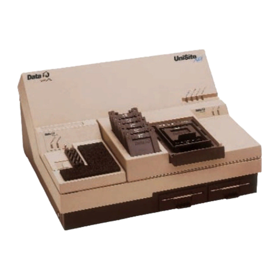
1. Introduction Contents of Package Figure 1-1 illustrates the contents of the UniSite-xpi system. Check the contents of your UniSite-xpi against the items shown in Figure 1-1. Figure 1-1 Contents of the UniSite-xpi UNISITE-XPI Universal Programmer BLANK MODULE COVER TASKLINK FOR... -
Page 23: Unisite-Xpi External Features
1. Introduction UniSite-xpi External Features The Front Panel The front panel features of UniSite-xpi are shown in Figure 1-2. Figure 1-2 Front Panel Features UNISITE STATUS INDICATORS a. POWER DISK STORAGE SLOTS b. TERMINAL PORT DEVICE SOCKET c. REMOTE PORT d. -
Page 24: The Back Panel
11. Function Specific Module (FSM)—A module that supports a special type of programming operation (e.g. set or gang programming). The Back Panel The back panel features of UniSite-xpi are shown in Figure 1-3. Figure 1-3 Back Panel Features PARALLEL... -
Page 25: Disks
Use the copies during daily operation. Algorithm/System Disks Algorithm/System disks contain the system software and programming algorithms for the currently supported devices. The UniSite-xpi is shipped with the algorithm files already stored on the Mass Storage Module (MSM). -
Page 26: Specifications
+10° to 40°C (+50° to 105°F) Storage: +4° to +50°C (+40° to +122°F) Transportation: -40° to +55°C (-40° to +130°F) Relative Humidity Operating: 20 to 80% noncondensing Storage: 10 to 90% noncondensing Operating: To 5,000 meters Altitude Storage: To 15,000 meters UniSite-xpi User Manual... -
Page 27: Safety
1. Introduction Safety The UniSite-xpi and all legacy programmers are certified by UL to comply with the following safety standards: Figure 1-4 LISTED UL Symbol Underwriters Laboratories — UL 60950 Third Edition and/or EN 60950 Third Edition 3T26 I.T.E. Electrostatic Discharge (ESD) IEC 801-2 ( ±... -
Page 28: Options
Keep Current Service —before the algorithms are available in the update kit. Keep Current algorithms are available on the Data I/O Home Page on the World Wide Web at http://www.dataio.com. For more information, see the Keep Current documentation located behind the Keep Current tab, or contact Data I/O Customer Support. - Page 29 4 pins. For example, if your UniSite has 10 pin drivers, you can program devices with up to 40 pins. If you want to program 48-pin devices, you will need to add two pin driver boards to your UniSite. UniSite-xpi User Manual...
-
Page 30: How Many Pin Driver Boards Do You Need (Legacy)
SOIC (PinSite) (PinSite) >84 * Requires the PGA Base, PSBASE-0402. Contact Data I/O Customer Support as listed in the Preface for more information. When you program devices with a PPI Base, we recommend that you install 17 boards, although the requirements vary among adapters. For the exact number of boards you need with a specific PPI Base, call Data I/O Customer Support as listed in the Preface. - Page 31 2. Setup and Installation This chapter describes how to set up UniSite-xpi and get it working with your equipment. Before you read this chapter, make sure you have read Chapter 1, “Introduction.” This chapter guides you through configuring the hardware and installing the system software.
-
Page 32: Setup And Installation
Algorithm/System disks contain the system software and programming algorithms for the currently supported devices. UniSite-xpi is shipped with the algorithm files stored on the Mass Storage Module (MSM). For updates, you will need to install new algorithm sets onto the MSM. See “Update System Software” on 2-24 for details. -
Page 33: Install A Module
PinSite Module. Installing a Module UniSite-xpi is designed to accept two modules: a small one on the left and a large one on the right. Each module allows you to support a specific package style or support special types of programming operations such as set or gang programming. -
Page 34: Removing A Module
Installing a Large Module Insert the two retaining hooks on the bottom of the large module into the two slots on the top right side of UniSite-xpi. Figure 2-1 shows a large module already inserted into UniSite-xpi. Carefully lower the back of the large module until the module connector touches its mating connector on UniSite-xpi. -
Page 35: Check The Line Voltage (On Older Units)
3. Choose Your Configuration Hardware Choices Review the equipment you have available and then decide which of the following hardware configurations you will use to control UniSite-xpi. • Connecting to a PC — Support for serial port and parallel port operations. -
Page 36: Connect Your Equipment
HiTerm (terminal emulation software) — Support for serial port operations only. HiTerm is available on the Utility Disk shipped with the UniSite-xpi, on the TaskLink for Windows CD, or it can be downloaded free from the Data I/O Web site. - Page 37 Start TaskLink. From the DOS prompt, type cd tl to change to the TaskLink directory. Type tl a to open TaskLink in Administrative mode. In Windows, you can create program items or shortcuts to run TaskLink. The command to run TaskLink in Administrative mode is tl.exe a. UniSite-xpi User Manual...
- Page 38 Written especially for UniSite, HiTerm terminal emulation software is a VT-100 terminal emulator that is required to perform several specialty operations. This interface also allows you to download files to UniSite-xpi at up to 115.2K baud on the serial communication port. HiTerm is included on the TaskLink for Windows CD and is installed when TaskLink for Windows is installed on your PC.
- Page 39 Edit the two lines that invoke HiTerm so they point to the drive and subdirectory containing the HiTerm files. An example of the program.bat file modified to reflect HiTerm’s installation in the c:\util\hiterm directory is shown below. UniSite-xpi User Manual...
-
Page 40: Connecting To A Host
Installation of HiTerm is now complete. Reboot your PC. The Next Step UniSite-xpi is now connected to your PC. Skip to the section titled “Install the Base” to continue with the setup and installation of UniSite-xpi. Connecting to a Host Connecting the programmer to a host allows you to use the host for remote file storage. -
Page 41: Connecting To A Terminal
“Install the Base” to continue with the setup and installation of the programmer. Connecting to a Terminal Connecting the programmer to a terminal is the simplest configuration. By connecting the programmer to a terminal, you can take advantage of all the programmer’s serial port capabilities. UniSite-xpi User Manual 2-11... -
Page 42: Figure 2-4 Transparent Mode
If your terminal type is listed below, then your terminal is compatible with the programmer. • ANSI 3.64 compatible terminals • DEC VT-100 compatible terminals • Qume QVT-101 compatible terminals • TELEVIDEO TVI-910 compatible terminals • Wyse WY-30 compatible terminals 2-12 UniSite-xpi User Manual... - Page 43 If your terminal has programmable function keys, the following table lists the expected codes for the four function keys: VT-100 Key Expected Code Wyse-30 Key Expected Code SOH @ CR SOH A CR SOH B CR SOH C CR UniSite-xpi User Manual 2-13...
- Page 44 Once you have established communication and the programmer is operating, you can change the communication parameters to suit your needs. Consult the manual supplied with the terminal if you need to change the terminal’s communication parameters. 2-14 UniSite-xpi User Manual...
-
Page 45: More About Cables
2-31). Some bases (such as the PPI Base) use device adapters. Follow the instructions in this section if the module installed on UniSite-xpi requires a base. For additional information, refer to Appendix A, “Using Modules,” and to “Install Devices” on page 2-30. -
Page 46: Removing A Base
LIFT BASE OUT Module BASE TOP VIEW 0565-2 6. Power Up the Programmer To power up the programmer, follow the steps below. Make sure the programmer is positioned so the fan on the bottom will not be obstructed. 2-16 UniSite-xpi User Manual... -
Page 47: Connecting The Power Cord
The programmer has completed powerup when the Self Test LED and disk drive LED are off. If the Self Test LED does go off, then go to the section titled “Are the Right LEDs Lit?” UniSite-xpi User Manual 2-17... -
Page 48: Figure 2-6 Front Panel Indicators
Contact your nearest Data I/O Customer Support office for more information. The different combinations of blinking LEDs are explained below. - Page 49 UniSite-xpi’s serial I/O parameters must match those of the equipment it is connected to. • UniSite-xpi must recognize the type of terminal that you are using. (Selecting the correct terminal type is described in the next section, “The Power-on Screen for Terminal Mode.”) The steps below tell you how to configure the Terminal port.
- Page 50 (see Step 4 or Step 7 below). If the operation is not supported on the parallel port, TaskLink switches to the serial port to complete the operation. Start TaskLink and select Options from the System menu. 2-20 UniSite-xpi User Manual...
-
Page 51: Figure 2-7 Tasklink Connection Established Message
One possible cause of the random characters is that the baud rates of the programmer and the controlling equipment do not match. In this case, follow the procedure in the next section to execute the AutoBaud function to “sync up” the baud rates. UniSite-xpi User Manual 2-21... -
Page 52: The Power-On Screen For Terminal Mode
At the bottom of the Power-on screen, the programmer displays the following prompt: Do you want to select a new terminal type? (Y/N) [N]: Press Y, E to select a new terminal type. NTER 2-22 UniSite-xpi User Manual... -
Page 53: Changing The Default Terminal
After the NTER programmer saves the currently selected terminal type as the power-on default, the Main Menu appears, indicating that the programmer is ready for operation. Go to the section titled “Insert Algorithm Disk.” UniSite-xpi User Manual 2-23... -
Page 54: Insert Algorithm Disk
9. Update System Software UniSite-xpi When you have a new version of system software you want to use with UniSite-xpi, perform the steps in the update instructions that accompany the new software. UniSite (Legacy) If your legacy UniSite does not have an MSM, you will need to boot the UniSite using the Boot Files disk each time you turn on the programmer. -
Page 55: Figure 2-9 Write-Enabled Disk
Software Version Compatibility While the UniSite-xpi Boot Files disk and Algorithm disks that are shipped with the system have the same version number, the version numbers of the disks do not have to be identical for the disks to work together. -
Page 56: 10. Set Up High Speed Download
Start HiTerm. Power up the programmer. If the programmer is already powered up, reboot it by pressing E +W. Complete booting up as normal. From the Main Menu, press M, C, E, S to get to the Serial Port Configuration screen. 2-26 UniSite-xpi User Manual... - Page 57 Download. As part of the configuration, you switched the User Menu Port from the Terminal port to the Remote port. The User Menu Port is the port through which the user interface data for UniSite-xpi is sent. User interface data includes screens, menu information, and online help. When shipped from the factory, the Terminal port is the User Menu Port.
-
Page 58: Changing The Powerup Defaults
HiTerm to download files from the PC to the programmer at 115.2K baud. For an example of downloading files to the programmer using High Speed Download, see “Session 17: Loading Data from a PC Using HiTerm” on page 3-46. 2-28 UniSite-xpi User Manual... -
Page 59: Using The Mass Storage Module (Hard Drive)
Make sure that drive A is empty. Reboot or powerup UniSite-xpi. When UniSite-xpi boots up and does not find a disk in drive A, it boots using the system software located on your MSM. Storage Capacity The MSM is partitioned into 4 logical drives, with specifications as... -
Page 60: Backing Up The Msm
Insert the DIP device into the socket. Make sure that the device is bottom justified, as shown in Figure 2-10. If the device is not bottom justified, the programmer will not read or program the device. 2-30 UniSite-xpi User Manual... -
Page 61: Installing A Matchbook
With the MatchBook open 90 degrees, insert it into the Base by setting the front edge onto the Base under the two locking tabs at the front edge of the Base. Then lower the back edge of the MatchBook into place on the Base. See Figure 2-11. UniSite-xpi User Manual 2-31... -
Page 62: Figure 2-12 Closing The Matchbook
Figure 2-12. CAUTION: Do not place excessive force on the top of the MatchBook, as this may cause premature wear on the conductive pad. Figure 2-12 Closing the MatchBook RETAINING LATCH 0539-4 2-32 UniSite-xpi User Manual... -
Page 63: Inserting A Plcc Or Lcc Device Into A Matchbook
Figure 2-12. CAUTION: Do not place excessive force on the top of the MatchBook, as this may cause premature wear on the conductive pad. UniSite-xpi User Manual 2-33... -
Page 64: Inserting An Soic Device Into A Matchbook
Figure 2-14, indicate the location of pin 1 for the various sizes of SOIC devices the SOIC MatchBook will accept. Figure 2-14 LEFT JUSTIFY PART Inserting an SOIC Device IN SOCKET PIN 1 ALIGNMENT FINGER (1 OF 6) 0568-3 2-34 UniSite-xpi User Manual... -
Page 65: Removing A Device From A Matchbook
The Base has been designed to allow you to replace the pads quickly and easily and to minimize downtime. Replacement pads are available from Data I/O. Pad Care Each pad should be inspected and cleaned as needed; we recommend you do this approximately every 1000 insertions or once a month. -
Page 66: Inserting Devices Into A Ppi Adapter
These PPI adapters accept a variety of device package types and pin configurations. The following figures show three common device packages and the proper device orientation in the adapter. Each adapter has an ICON showing the proper device orientation. 2-36 UniSite-xpi User Manual... -
Page 67: Figure 2-16 Tsop Device Orientation
To remove the device, press down on the socket edges and lift the device out. Figure 2-16 DEVICE TSOP Device Orientation PIN 1 OF SOCKET TSOP SOCKET PIN 1 STANDARD PINOUT ICON REVERSE PINOUT ICON 1327-1 UniSite-xpi User Manual 2-37... -
Page 68: Figure 2-17 Qfp Device Orientation
Orient the SDIP device in the socket with pin 1 at the top left and bottom justified as shown in Figure 2-18. Figure 2-18 Shrink Dip Device Orientation SDIP SOCKET PIN 1 SDIP ORIENTATION ICON 1329-1 2-38 UniSite-xpi User Manual... -
Page 69: Maintenance
Changing the Line Voltage (Legacy) Data I/O has configured UniSite to operate on 115 Vac unless specified otherwise. Older units have a line voltage indicator that is visible through the window in the back panel door covering the voltage selector wheel, shown in Figure 2-19. -
Page 70: Replacing The Line Fuse
Determine whether the fuse is intact. If it is intact, proceed to Step 4. If the fuse is blown, install a new fuse. CAUTION: For continued protection against the possibility of fire, replace only with a fuse of the correct voltage, current and type ratings. 2-40 UniSite-xpi User Manual... -
Page 71: What To Do Next Time
You are now ready to begin a new session on the programmer. Refer to step 12, “Install Devices,” on page 2-30 for instructions on how to install devices. Refer to Chapter 3 “Getting Started” for tutorials on how to use your programmer. UniSite-xpi User Manual 2-41... - Page 72 2. Setup and Installation 2-42 UniSite-xpi User Manual...
-
Page 73: Getting Started
Sessions, you will learn how to select a device, load device data, edit data, program the device, and verify that it programmed correctly. The Sessions will not teach you everything about UniSite-xpi; instead, they will give you a working knowledge of the programmer. If you are using TaskLink for Windows or TaskLink for DOS, see the online Help for more detailed information. -
Page 74: What Will I Learn
Session 16: Selecting a Translation Format Session 17: Loading Data from a PC Using HiTerm Session 18: Loading Data from a Host Session 19: Editing Data Session 20: Programming a Memory Device Session 21: Verifying a Device UniSite-xpi User Manual... -
Page 75: Outline Of The Programming Operation
The Verify Device operation (included with programming) compares the data in a programmed device to the data in programmer RAM. Additional verify operations provide information about programming errors. Logic device verification can include functional testing. UniSite-xpi User Manual... -
Page 76: Tutorials For Tasklink For Windows Mode
Session 1: Selecting a Device On the TaskLink main screen, under the System menu select Select Programming System. Figure 3-2 System Menu: Select Programming System From the Programmer Type list, highlight UniSite-xpi and click OK. Figure 3-3 Programmer Type UniSite-xpi User Manual... -
Page 77: Figure 3-4 System Menu: Simulation Mode
On the TaskLink main screen, under the System menu select Simulation Mode. Figure 3-4 System Menu: Simulation Mode Next specify the device to be programmed. From the TaskLink Setup menu, select Select Device. Figure 3-5 Setup Menu: Select Device UniSite-xpi User Manual... -
Page 78: Session 2: Setting Programmer Properties
Select the General tab and enter the parameters that you wish to use. These parameters determine what device operations are performed before, during and after programming. For more detailed information about each parameter, see TaskLink context-sensitive Help. UniSite-xpi User Manual... -
Page 79: Figure 3-8 General Tab
To ensure consistent checksum, you can preload all address locations into RAM with a known hexadecimal value (many data files do not contain data for every memory address). For more information, see TaskLink online Help Click OK. Figure 3-9 Memory Tab UniSite-xpi User Manual... -
Page 80: Session 3: Loading Data
When the data file is transferred to a programmer, the programmer must be set to handle the appropriate translation format. For more information on translation formats, see Chapter 6 “Translation Formats.” Select the appropriate translation format from the drop-down list. UniSite-xpi User Manual... -
Page 81: Session 4: Selecting Processes
00000000. When connected to a programmer and loading real data, the checksum will display actual values. Session 4: Selecting Processes After loading data into programmer RAM, the next step is determining which processes the programmer will perform on the device. UniSite-xpi User Manual... -
Page 82: Figure 3-15 Select Process
From the Process menu, select Select Process. Figure 3-14 Process Menu: Select Process In the Select Process dialog, enter a check for each process you want performed on the device to be programmed. Click OK. Figure 3-15 Select Process 3-10 UniSite-xpi User Manual... -
Page 83: Session 5: Programming A Device
You may also enter a Session ID name or number. A Session ID is optional and helps when tracking statistics. In this example, we’ll enter a Session ID of 01-03-05. Click OK. Figure 3-17 Process Devices UniSite-xpi User Manual 3-11... -
Page 84: Figure 3-18 Waiting For Start
After reaching the Pass Limit, or programming the desired number of devices, the Processing Status window displays the results of the programming session. In this example, we processed five devices and all passed. Figure 3-19 Results of Programming Session To finish, click End Session. 3-12 UniSite-xpi User Manual... -
Page 85: Figure 3-20 Tasklink Main Screen With Last Job Summary
This returns you to the TaskLink main screen which now displays a Last Job Summary about the most recently completed programming session. Figure 3-20 TaskLink Main Screen with Last Job Summary This completes the process of programming a device. UniSite-xpi User Manual 3-13... -
Page 86: Tutorials For Tasklink For Dos Mode
Enter.) From the System menu, select Programmer Type. Figure 3-21 System Menu: Programmer Type On the Programmer Type screen, select UniSite and click OK. Figure 3-22 Programmer Type 3-14 UniSite-xpi User Manual... -
Page 87: Figure 3-23 Setup Menu: Select Device
From the Setup menu, select Select Device. Figure 3-23 Setup Menu: Select Device Scroll through the list until the manufacturer of the device you want to use is highlighted, then click OK. Figure 3-24 Select Manufacturer UniSite-xpi User Manual 3-15... -
Page 88: Session 7: Setting Programmer Properties
RAM with a known hexadecimal value (many data files do not contain data for every memory address). To do this, select Specific under Automatic RAM Fill and enter a value (usually 00 or FF) to be placed in RAM before a file is loaded. 3-16 UniSite-xpi User Manual... -
Page 89: Session 8: Loading Data
RAM with the data to be programmed in the device. In this example, the data is stored in a file on a disk. From the Data menu, select Load RAM from PC Disk File. Figure 3-28 Data Menu: Load RAM UniSite-xpi User Manual 3-17... -
Page 90: Figure 3-29 Pc Disk File
Type the name of the data file in the PC Disk File box or press F2 to display the Data File selection box. Figure 3-29 PC Disk File In the Data File list box, search for and select a file from any drive accessible from your PC. Figure 3-30 Select Data File 3-18 UniSite-xpi User Manual... -
Page 91: Session 9: Selecting Processes
00000000. When connected to a programmer and loading real data, the checksum will display actual values. Session 9: Selecting Processes After loading data into programmer RAM, the next step is determining which processes the programmer will perform on the device. UniSite-xpi User Manual 3-19... -
Page 92: Session 10: Programming A Device
Figure 3-34 Process Devices When actually programming a device, you will be prompted to insert the device to be programmed. For information about inserting devices, see “Install Devices” on page 2-30. 3-20 UniSite-xpi User Manual... -
Page 93: Figure 3-35 Statistics
The Last Device box displays “Pass” on a green background or a message that describes a failure on a red background. Figure 3-35 Statistics This completes the process of programming a device. UniSite-xpi User Manual 3-21... -
Page 94: Tutorials For Hiterm (Terminal) Mode
Chapter 2, “Setup and Installation.” You should also have read Chapter 1, “Introduction.” General Information About HiTerm UniSite-xpi should be powered up and you should be looking at the Main Menu, shown in Figure 3-36. Figure 3-36... -
Page 95: The Unisite-Xpi Screen
The UniSite-xpi Screen You will see a consistent format to the screens as you use UniSite-xpi. Most screens, such as the screen shown in Figure 2-23, are broken into five areas: the status window, the message bar, the command window, the dialog window, and the reminder bar. -
Page 96: Moving The Cursor
NTER Accessing Online Help Online Help screens are available throughout UniSite-xpi and provide both general help and context-sensitive help. Context-sensitive help gives you help text that is specific to a particular field on the screen. For example, if you are in a parameter selection screen, each parameter on the screen has a different piece of help text associated with it. -
Page 97: Figure 3-38 Areas Of The Help Screen
Chapter 7, “Messages.” Non-fatal error messages are generally displayed in the message bar. To access the online help for the message, press F3 or ?. UniSite-xpi displays the online help for the message. Exit the message help screen as you would any help screen. -
Page 98: Using Key Functions
3. Getting Started Using Key Functions Some of UniSite-xpi’s functions may be performed by pressing a key or a combination of keys. When using the C key, hold it down and then momentarily press the second key. The key functions are listed below with their corresponding keystroke sequence. -
Page 99: Session 11: Navigating Through The Menus
Verify Device A verify operation compares the data in a programmed device against the data in UniSite-xpi’s RAM or against the data in a disk file. In the case of logic devices, verifying can also include functional testing. Verify is... -
Page 100: Select Online Help
To leave the help screen and return to the Self-test screen, press F2. (Remember, if you forget what key to press, look at the reminder bar on the bottom of the screen for a quick reminder.) You should now be looking at the Self-test screen. 3-28 UniSite-xpi User Manual... -
Page 101: Exit The Online Help
F1 once to return to the Main Menu. Step through the menus until you are comfortable. (Access the online help if you want to.) When finished, return to the Main Menu. This completes your tour of UniSite-xpi’s user interface and online help system. Review In this Session you learned how to navigate through the UniSite-xpi interface. -
Page 102: Session 12: Selecting A Device
Before You Begin You should have completed Session 1, which introduces you to the UniSite-xpi interface. Also, make sure that you are at the Main Menu before you start. (Press F1 to return to the Main Menu.) Can I Use Another... - Page 103 Single Mode do not make devices that can be programmed in Gang or Set Mode. As with the Device Type field, UniSite-xpi only displays the manufacturers that make devices that fit the currently selected filters. For this Session, we will be programming a single 27256 EPROM; so, set the Mode filter to Single.
-
Page 104: Select A Device Part Number
For example, in Figure 3-43, you would type 7 and press NTER UniSite-xpi loads the algorithm for the device you selected, in this case an AMD 27256. While UniSite-xpi is loading the algorithm, the action symbol rotates. (Remember, the action symbol is located at the left end of the message bar at the top of the screen.) -
Page 105: Accessing Device-Specific Online Information
Done When UniSite-xpi has loaded the programming algorithm for the device you have selected, UniSite-xpi will return to the Main Menu. The manufacturer and part number of the device you selected will appear in the status window. At this point, you will see only screens related to the type of device you selected. -
Page 106: Can I Use Another Device
Device? If you have not downloaded a Keep Current algorithm for your UniSite-xpi, you will not be able to complete this Session. However, you can still read the remainder of the Session to learn more about how to select a Keep Current algorithm. Or, you can skip this Session and continue with Session 4. -
Page 107: Figure 3-45 The Keep Current Part List
If you do not see the Keep Current Part List screen, you are probably looking at a screen that describes the Keep Current service. UniSite-xpi will not display the Keep Current Part List screen if you do not have any Keep Current algorithms. -
Page 108: Select The Keep Current Algorithm
Notice that the Keep Current Part List screen lists both the device manufacturer and the device part number. Also, notice that the devices are listed in no particular order: UniSite-xpi lists the devices in the order that they are found on the disk. -
Page 109: Special Note
Keep Current algorithm for the Cruft 1263 on the Data I/O Web site. • The next day, you go to the Data I/O Web site and download the new algorithm for the Cruft 1263. • In August, Data I/O releases version X.5 system software, complete with the new algorithm for the Cruft 1263. -
Page 110: Session 14: Loading Data From A Device
You should also have Site48 installed in UniSite-xpi. If Site48 is not installed in UniSite-xpi, or if you would like to review the instructions for installing/removing or Site48, see Chapter 2, “Setup and Installation.”... -
Page 111: Insert The Device
3. Getting Started Insert the Device Make sure Site48 is properly installed in UniSite-xpi. If the device socket is locked, unlock it by pulling up the socket lever. Insert the device into the device socket, making sure that the device is bottom-justified and that pin 1 is in the upper-left corner. -
Page 112: Parameter Screens
UniSite-xpi performs an operation. Quantifying parameters, such as Block Size or I/O Translation Format, give UniSite-xpi a range or variable to use in an operation. Six different parameters are shown in Figure 3-47, including Destination and User Data Size. -
Page 113: Setting The Parameters
NTER loading. When UniSite-xpi is finished loading the data from the device, it displays an 8-digit sumcheck of the data loaded. (UniSite-xpi displays a 4-digit, 8-bit sumcheck when you load data from a logic device.) UniSite-xpi User Manual... -
Page 114: Session 15: Loading Data From Disk
UniSite-xpi’s internal disk drives. When you have completed this Session, skip the next two Sessions and continue with Session 8. If you have a data file you want to download to UniSite-xpi, you should skip this Session and complete the next two Sessions. -
Page 115: Figure 3-49 The File Menu
Create a binary file on a disk and place the disk in drive A. Select Load File from the File menu. The dialog window displays a directory of the files on the disks in UniSite-xpi’s two disk drives. (Notice that the Load File command displays a directory similar to the View Directory command.) A screen similar to what you will see is shown in Figure 3-50. -
Page 116: Review
Review You can load device data into UniSite-xpi by loading a data file from one of UniSite-xpi’s internal disk drives. Use the commands on the File Operations menu (such as the Load File command) if your data file is stored in binary image format. -
Page 117: Session 16: Selecting A Translation Format
This Session and the following Session are companion Sessions. This Session introduces you to translation formats and shows you how to select a translation format. The next Session shows you how to load a data file through UniSite-xpi’s Terminal port. About Translation Formats Translation formats represent different ways of representing the device data in a data file. -
Page 118: Review
In this Session, you will learn how to use HiTerm to download data from a PC to UniSite-xpi through one of the serial ports on UniSite-xpi. Note: If you are using a DOS-based PC, we recommend you use HiTerm as your terminal emulation software. -
Page 119: Figure 3-52 The Download Data From Host Screen
Qualifying parameters, such as Source and Destination, control the type of operation to perform. Quantifying parameters, such as Block Size or I/O Translation Format, give UniSite-xpi a range or variable to use in an operation. Seven parameters are shown in Figure 3-52, including Source, Memory Begin Address, and Download Host Command. -
Page 120: Downloading The File
Earlier in this Session, you entered the parameters for the download, but you left the Download Host Command parameter blank. The Download Host Command is a command that UniSite-xpi sends to the PC to initiate the download. Because you are running HiTerm, you can specify a special Download Host Command, the command. -
Page 121: After The Download
If the two sumchecks are different, then the data programmed is not the same as the data downloaded. Review In this Session, you learned how to download data to UniSite-xpi from a host connected to UniSite-xpi’s Terminal port. The steps were •... -
Page 122: Session 18: Loading Data From A Host
This eliminates the need for a switch box or a second link to the host, and enables you to download directly from the host to UniSite-xpi. The host could be a networked file server such as a VAX or a Sun. When set up properly, the terminal connected to UniSite-xpi can control both UniSite-xpi and the remote host. -
Page 123: What To Transfer
Figure 3-54 The Download Data from Host Screen Look at the parameters and make sure they reflect your system configuration. Use the following settings if your host is connected to the Remote port on UniSite-xpi: • Source—Remote port • Destination—RAM •... -
Page 124: Downloading The File
Qualifying parameters, such as Source and Destination, control the type of operation to perform. Quantifying parameters, such as Block Size or I/O Translation Format, give UniSite-xpi a range or variable to use in an operation. Seven parameters are shown in Figure 3-54, including Source, Memory Begin Address, and Download Host Command. -
Page 125: After The Download
If the two sumchecks are different, then the data programmed is not the same as the downloaded data. Review In this Session, you learned how to download data to UniSite-xpi from a host connected to the Remote port on UniSite-xpi. The steps were •... -
Page 126: Session 19: Editing Data
3. Getting Started Session 19: Editing Data In the previous Session, you loaded a data file into UniSite-xpi. In this Session, you will learn how to edit that data file. Before You Begin Return to the Main Menu before you begin this Session. You should also select a memory device before you begin this Session. -
Page 127: Moving Around
Type o to correct the spelling mistake. Next, move the cursor to date and change it to read data. The previous two corrections were done in overtype mode: the typed characters replaced the previous characters. The next correction will be done in insert mode. UniSite-xpi User Manual 3-55... -
Page 128: Restoring Your File
The third and last correction is adding the word UniSite-xpi before the period below the word loaded. Move the cursor on top of the period and... -
Page 129: Can I Use Another Device
PROGRAM MEMORY DEVICE (all parameters) PROGRAM MEMORY DEVICE (non-default) There are two types of programming parameter screens: simple and complex. UniSite-xpi defaults to displaying the simple, Non-default parameters screen. Figure 3-57 The Program Memory Device... -
Page 130: Programming The Device
Parameters either qualify or quantify UniSite-xpi’s actions. Qualifying parameters, such as Illegal Bit Check, control whether or not UniSite-xpi performs an operation. Quantifying parameters, such as Block Size, give UniSite-xpi a range or variable to use in an operation. Which Screen Should I Use? During the course of normal programming, you usually only need the parameters on the Non-default screen. -
Page 131: Review
NTER When UniSite-xpi is finished programming, it displays an 8-digit sumcheck of the data programmed into the device. (UniSite-xpi displays a 4-digit sumcheck when you program a logic device.) Session 21: Verifying a Device Once you have programmed a device, you can perform a number of different device checks and programming tests on the device. -
Page 132: Setting The Verify Parameters
Session, you probably do not need to set any parameters. But, to be sure, check the parameters shown in Figure 3-60 against the parameters you see on your UniSite-xpi. Note: Remember that the displays may look different if you are using a device other than an AMD 27256. -
Page 133: Verifying The Device
When you have entered the verify parameters, press E to begin the NTER verify operation. When UniSite-xpi is finished verifying, it displays an 8-digit sumcheck of the data in the device. (UniSite-xpi displays a 4-digit sumcheck when you verify a logic device.) UniSite-xpi User Manual 3-61... - Page 134 3. Getting Started 3-62 UniSite-xpi User Manual...
-
Page 135: Commands
This chapter describes the commands you can access from UniSite-xpi’s menus. Menu Organization The interrelation of UniSite-xpi menus and commands is shown in the command tree in Figure 4-1. Menu Maps Each command description includes a map, which displays part of the command tree representing your location and shows you the path to the command. -
Page 136: Figure 4-1 The Command Tree
Copy File Remote Control Duplicate Disk pg. 4-82 Format Disk Self-test Download Data pg. 4-82 Upload Data Compare Data Transfer Data Format Select pg. 4-83 Input From Disk Output To Disk Yield Tally pg. 4-93 Serial Output 0542-9 UniSite-xpi User Manual... -
Page 137: Overwriting User Ram
Algorithms Factory Default Settings UniSite-xpi’s system parameters are initialized to certain settings at the factory. You can restore these factory defaults at any time by selecting configuration file number 0 from the More Commands/Configure System/Restore menu. From the Restore System Parameters menu, press 0, E to re-elect the factory settings. - Page 138 Remote Upload record size Verify Data Format Verify Passes * This parameter is not restored when the Restore Configuration opera- tion is performed. However, it is used at powerup if it is saved as a powerup parameter. UniSite-xpi User Manual...
-
Page 139: Select Device
After setting the Algorithm Type parameter, press F1 to return to the Main Menu. Note: See “Save System Parameters” on page 4-38 for instructions on how to save your Algorithm Type and other parameter changes as power-up defaults. UniSite-xpi User Manual... -
Page 140: Selecting A Device
For example, if 2)KEEP CURRENT is a choice, type the number 2 for the manufacturer and press E NTER UniSite-xpi User Manual... -
Page 141: After You Select A Device
Note: If only the footnote number appears in the message bar, the programmer could not access the devfnote.sys file. Check to see if the correct disk is inserted into the programmer’s drive. Footnote (device-specific) information can also be found in the Device List. UniSite-xpi User Manual... -
Page 142: Cross Programming
Main Menu appears. Select the Program Devices NTER screen and will be displayed in the PART # field at the top 16V8 as 16L8 of the screen. Insert the 16V8 and press E . The 16V8 is programmed NTER as a 16L8. UniSite-xpi User Manual... -
Page 143: Quick Copy
Press E to begin loading the master data into RAM. When the NTER data in the master device has been loaded, UniSite-xpi displays OPERATION COMPLETE. Sumcheck = xxxxxxxx (8-bit) Hit return Note: (Legacy) If you are using the Quick Copy function with SetSite, you must press Return again at this point. -
Page 144: Load Device
Select Load Device from the Main Menu. The Load Logic Device screen appears. Press E to begin the loading. NTER When the load operation is complete, UniSite-xpi displays the following message in the message bar: OPERATION COMPLETE. Sumcheck = xxxx (8-bit) 4-10 UniSite-xpi User Manual... -
Page 145: Load Memory Device
16 bits on the Load Memory Device screen, it requires two devices to store each 16-bit word. Typing 1 for the next set member directs UniSite-xpi to load the first device in the set at even-address bytes of the memory block. Typing 2 directs UniSite-xpi to load the second device at odd address bytes of the memory block. - Page 146 • Set Auto-increment—This option, used in serial set mode, automatically directs UniSite-xpi to the next block in the set that is to be loaded. For example, if you have four 1K x 8 devices to load into a 4K x 8 block of memory, using the auto-increment option directs UniSite-xpi to point to the first memory address of the next 1K block after each device had been loaded.
-
Page 147: Program Device
Specify the parameters you want, then press E to begin the NTER programming. When the programming is complete, UniSite-xpi displays the following message in the message bar: OPERATION COMPLETE. Sumcheck = xxxx (8-bit) The following parameters can be specified on the Program Logic Device screen: •... - Page 148 RAM indicates a specific bit should be in an unprogrammed state while the corresponding bit in the device is in a programmed state. The device cannot be programmed if UniSite-xpi detects an illegal bit. This parameter is enabled by default.
- Page 149 • Verify Passes (0,1,2)—Selects the number of times to test the device. 0 directs UniSite-xpi not to test the device. 1 directs UniSite-xpi to test the device once at the device manufacturer’s nominal Vcc. 2 directs UniSite-xpi to verify the device at the device manufacturer’s recommended high and low Vcc levels.
-
Page 150: Program Memory Device
8-bit devices and have specified a word width of 16 bits on the Program memory device screen, two devices are required to store each 16-bit word. 1 directs UniSite-xpi to program the first device in the set with even-numbered addresses of the memory block. - Page 151 Program Signature—Available on only a few devices, the program signature is a user-definable field that allows the user to program data into the program signature array. Software Data Protection (Y,N)—When enabled, prevents writing to a device. UniSite-xpi User Manual 4-17...
- Page 152 Illegal Bit Check (Y,N)—Enables or disables the illegal-bit test. This test compares data in a device against data in UniSite-xpi’s RAM to determine if the device has already-programmed locations of incorrect polarity. For example, UniSite-xpi returns an illegal-bit error...
-
Page 153: Enhanced Security Fuse Capability
• Verify Passes (0,1,2)—Selects the number of times to test the device. 0 directs UniSite-xpi not to test the device. 1 directs UniSite-xpi to test the device once at the device manufacturer’s nominal Vcc. 2 directs UniSite-xpi to verify the device at the device manufacturer’s recommended high and low Vcc levels. -
Page 154: Verify Device
A. Fuse Verification checks the fuse pattern programmed into the device with the pattern in UniSite-xpi’s memory. Vector Verification functionally tests the device, using structured test vectors stored in memory. A directs UniSite-xpi to perform both fuse verification and vector verification. Press S to step through the three choices. -
Page 155: Verify Memory Device
• Verify Passes (0,1,2)—Selects the number of times to test the device. 0 directs UniSite-xpi not to test the device. 1 directs UniSite-xpi to test the device once at the device manufacturer’s nominal Vcc. 2 directs UniSite-xpi to verify the device at the device manufacturer’s recommended high and low Vcc levels. - Page 156 Verify Memory Device screen, then two devices are required to verify each 16-bit word. Typing 1 for the next set member directs UniSite-xpi to verify the first device in the set with even-numbered addresses of the memory block. Typing 2 directs UniSite-xpi to use odd-numbered addresses.
- Page 157 • Verify Passes (0,1,2)—Selects the number of times to test the device. 0 directs UniSite-xpi not to test the device. 1 directs UniSite-xpi to test the device once at the device manufacturer’s nominal Vcc. 2 directs UniSite-xpi to verify the device at the device manufacturer’s recommended high and low Vcc levels.
-
Page 158: More Commands
Self-test—Performs diagnostic checks on UniSite-xpi’s circuitry. • Transfer Data—Allows you to upload or download data to or from UniSite-xpi. Also allows you to select or change the data translation format. • Yield Tally—Allows you to view or clear programming statistics. -
Page 159: Configure System
The commands on the Configure System menu allow you to accomplish these basic tasks: • Change communications protocols between UniSite-xpi and the other equipment connected to UniSite-xpi, such as a terminal or a host computer. • Configure the Remote and Terminal ports so they will be compatible with your terminal or host computer. - Page 160 Enable CTS/DTR Main Menu Job Files * This parameter can be saved with the Save System Configuration command and is read on powerup, but this parameter is not restored when a Restore System Configuration command is performed. 4-26 UniSite-xpi User Manual...
- Page 161 • Verify Passes (0,1,2)—Selects the number of times to test the device. 0 directs UniSite-xpi not to test the device. 1 directs UniSite-xpi to test the device once at the device manufacturer’s nominal Vcc. 2 directs UniSite-xpi to verify the device at the device manufacturer’s recommended high and low Vcc levels.
- Page 162 Select Device command, UniSite-xpi displays a Manufacturer List screen containing only the manufacturers found in the alg.ext file. If this parameter is set to E and UniSite-xpi cannot find the alg.ext file, UniSite-xpi displays the following message in the message bar: Cannot access system file.
- Page 163 It is also automatically set to a smaller value if the Device Begin Address is nonzero. This parameter can be changed if desired. If a zero is entered, the Device Block Size is set to the device size. UniSite-xpi User Manual 4-29...
- Page 164 • Illegal Bit Check (Y,N)—Enables or disables the illegal-bit test. This test compares data in a device against data in UniSite-xpi’s RAM to determine if the device has already-programmed locations of incorrect polarity. For example, UniSite-xpi returns an illegal-bit error...
- Page 165 Display Device Footnote (Y,N)—When enabled, this feature enables the automatic display of device specific information (if any is available for the selected device). • Abort on Empty Socket (Y,N)—When this option is enabled, all device operations will automatically be aborted on empty sockets. UniSite-xpi User Manual 4-31...
- Page 166 RAM Device Selection—When selected, allows the device programming algorithms to reside in user RAM. This feature requires UniSite-xpi to contain the 4 MB or 8 MB option and allows much faster device selection than the normal method of loading the algorithm from the disk each time a device is selected.
- Page 167 (No parity), O (Odd parity), and E (Even parity). Press S to cycle PACE through the three values. • Data Bits (7,8)—Specifies the number of data bits UniSite-xpi recognizes during serial communication. Press S to toggle PACE between the two values.
- Page 168 • Download Echoing (Y,N)—Displays the data being downloaded. This may slow down UniSite-xpi in receiving data and is not recommended for high baud rates, such as 9600 and above. Download echoing may not be used with the binary formats.
- Page 169 Data operation. • High Speed Download (Y,N)—When enabled, this parameter allows UniSite-xpi to download data from a PC at 115.2 kbaud. For high speed download to work, this parameter must be set to Y and the following conditions must be met: –...
- Page 170 This type of condition may exist in spite of the use of hardware and/or software handshaking on the host and UniSite-xpi. This condition is most likely to occur on hosts that cannot accept incoming data fast enough at high baud rates.
- Page 171 I/O format that utilizes checksums (such as Format 87) selected. Note the checksum reported by UniSite-xpi when the transfer is complete. Then transfer the same data back to UniSite-xpi while UniSite-xpi is performing the compare data function, again noting the checksums.
- Page 172 Com- mands Parame- This feature is useful if you want UniSite-xpi to power up with preset parameters. This feature is also useful if multiple users prefer to have their own set of parameters easily available. To save a system configuration, follow these steps:...
- Page 173 4. Commands When you have UniSite-xpi configured the way you want, go to the Save screen and select a file number in which to store the configuration file. The file number must be between two and nine. File numbers zero through two are reserved for factory defaults, power-up defaults, and CRC defaults.
-
Page 174: Programmer Id
This is because the power-up defaults, in addition to the factory defaults and any user-defined configurations, are stored in a file named sysparm.sys on the UniSite-xpi System disk. Now, the following scenario is possible: •... - Page 175 • Update all three UniSite-xpis to a new version of system software. • Make backups of the new System and Algorithm disks. • Perform steps 1 to 5 as described above on one UniSite-xpi. • Repeat step 5 for the remaining two UniSite-xpis.
- Page 176 Select the More Commands/Configure System/Terminal Type command. At this point UniSite-xpi displays the default and current terminal types, and the available terminal types. Select a terminal type, enter the number corresponding to that terminal type, and press E .
-
Page 177: Keep Current
When you select the View command, the dialog window fills with a directory listing. UniSite-xpi displays up to 10 files at one time. If there are more than 10 files, press C + N to display the next page of files. - Page 178 On the Replace/Restore screen, the dialog window fills with a directory listing with parts marked as “replaced” displayed in reverse video. UniSite-xpi displays up to 10 files at one time. If there are more than 10 files, press C + N to display the next page of files.
- Page 179 When you select the Delete command, the dialog window fills with a directory listing. UniSite-xpi displays up to 10 files at one time. If there are more than 10 files, press C + N to display the next page of files.
-
Page 180: Custom Menu Algs
A and B (outdated Keep Current algorithm files have version numbers older than the current system software version number). UniSite-xpi displays up to 10 files at one time. If there are more than 10 files, press C + N to display the next page of files. Press C P to display the previous page of files. - Page 181 RAM to perform the operation. If you press E , the RAM file(s) NTER are cleared and the operation continues. If you don’t want RAM files cleared, cancel the operation by pressing C + Z. UniSite-xpi User Manual 4-47...
- Page 182 Custom Menu disk. 10. Insert the Custom Menu disk and press E to save your changes NTER to disk. To add additional devices to your Custom Menu, use the Add command (described below). 4-48 UniSite-xpi User Manual...
- Page 183 Type the number corresponding to the device you wish to add to your Custom Menu, and press to add the device. (C + N to see the next page of devices.) NTER UniSite-xpi User Manual 4-49...
- Page 184 To delete devices from a Custom Menu, follow these steps: Select the Delete command. Insert the disk that contains your Custom Menu and press E NTER continue. Follow the directions on the screen (inserting disks if prompted). 4-50 UniSite-xpi User Manual...
- Page 185 To update the Custom Menu, press E (if you do not want to NTER update the Custom Menu, press F2). When you are done updating Custom Menus, press F2 to return to the Custom Menu Algs menu. UniSite-xpi User Manual 4-51...
-
Page 186: Mass Storage
In order to install the new software, the programmer must be booted from the floppies of the version to be installed. If this option is enabled, the field Maintain Previous Configuration will appear. 4-52 UniSite-xpi User Manual... -
Page 187: Device Checks
Insert Algorithm Set 3 Disk Algorithm disk containing Algorithm Set 3. CAUTION: Do not remove disks from UniSite-xpi during this operation unless UniSite-xpi prompts you to do so. When the Mass Storage software installation is done, OPERATION is displayed in the message bar. - Page 188 Device To sumcheck a logic device, follow these steps: Select and socket a logic device. Press E , and UniSite-xpi calculates the 4-digit sumcheck of the NTER fuse pattern. The sumcheck is displayed in the message bar. 4-54 UniSite-xpi User Manual...
- Page 189 Total Set Size—Specifies how many virtual devices are in the set to be sumchecked. Either enter a number between 1 and 99, or change one of the following parameters and UniSite-xpi will calculate the Total Set Size: Memory Begin Address, User Data Size, or Data Word Width.
- Page 190 D directs UniSite-xpi to calculate and display the checksum based on the number of bits per word in the device width. This option is for use with 16- and 32-bit devices. B directs UniSite-xpi to calculate and display the checksum based on the number of bits per word in the device width, and also to display the 8-bit checksum.
- Page 191 ID of the socketed device. Illegal Bit Check The Illegal bit test compares data in a device against data in UniSite-xpi’s RAM to determine if the device has already-programmed locations of incorrect polarity. For example, UniSite-xpi returns an illegal-bit error in...
- Page 192 Logic To check a logic device for illegal bits, follow these steps: Select and socket a logic device. Press E , and UniSite-xpi begins the Illegal Bit Check. The results NTER are displayed in the message bar. Memory Device Illegal Bit Check If you have selected a memory device, then the Illegal Bit Check screen for memory devices appear.
- Page 193 Check mands To blank check a device, follow these steps: Select and socket a device. Press E . UniSite-xpi checks the device and respond with NTER OPERATION FAILED: Non-blank device. if the device is non-blank, or OPERATION COMPLETE if the device is blank.
- Page 194 The Electronic Erase is part of the normal programming cycle. Before programming an electronically erasable device, UniSite-xpi checks the device and displays a warning if the device is non-blank. If you enable the erasing of the device, UniSite-xpi erases the device before programming the device. Underblow/Overblow...
- Page 195 Exit Exits the Under/Overblow screen and returns UniSite-xpi to the Device Checks menu UniSite-xpi User Manual 4-61...
-
Page 196: Edit Data
Use the commands on the Edit Data menu to make changes to data stored in RAM or to data stored in a disk file. When you select the Edit Data command, UniSite-xpi displays a menu corresponding to the type of device that is currently selected. There are separate editors for memory and logic devices. - Page 197 Moves the cursor to a specific fuse. A highlighted area appears just after the prompt at the ^B: Jump to Fuse bottom of the screen. Type in the fuse number that you want to jump to and press E NTER UniSite-xpi User Manual 4-63...
- Page 198 Move the cursor to the Edit Begin Vector field and enter the desired vector number. The vector number you type must be less than or equal to the last vector in RAM or the disk file. This field defaults to 1. 4-64 UniSite-xpi User Manual...
- Page 199 If more than 16 Ds or Us are used in any one test vector, the extra Ds or Us are ignored during test. Ignores the state of an output pin. UniSite-xpi applies a logic level specified by a JEDEC file. X field value (1 or 0) or a low is used as the default value.
- Page 200 C + W command. When you execute this command, the saved vector is placed in front of the vector highlighted by the cursor. Exit Editor Exits the vector editor and returns to the previous screen. 4-66 UniSite-xpi User Manual...
- Page 201 To clear vectors, press E NTER Note: Only vectors in UniSite-xpi’s RAM are cleared. This command cannot be used to clear vectors stored on a disk. Edit Memory Menu The Edit Memory menu appears if you have selected a memory device.
- Page 202 Using the address offset can save much calculation time on files written on a host system and then downloaded to UniSite-xpi. For example, if your host system data file was written using a begin address of 1000H, you could specify an offset of 1000H.
- Page 203 Prev Block Displays the previous block of memory data. Restore Block Returns the current page of data to its original state (before editing began). The page is restored only if there have been no paging commands. UniSite-xpi User Manual 4-69...
- Page 204 For 8-bit data, the data is entered in bytes, and for 16-bit data, the data is entered in words. Exits the memory editor and returns Exit Editor UniSite-xpi to the Edit menu. 4-70 UniSite-xpi User Manual...
- Page 205 Move Pro- Com- grammer mands Memory To copy data stored in memory, follow these steps: Specify the parameters described below. Press E to begin the Data Copy operation. UniSite-xpi displays NTER when the process is complete. Done UniSite-xpi User Manual 4-71...
- Page 206 Memory To fill a block of memory, follow these steps: Specify the parameters described below. Press E to begin the Fill function. UniSite-xpi displays NTER Done when the operation is completed. The available parameters are described below. •...
-
Page 207: File Operations
DOS-compatible 3.5” disk. The files on drive A are displayed first. UniSite-xpi displays 28 files at one time. If your disk(s) contains more than 28 files, they are displayed on the next page(s). Press C to advance to the next page of files. - Page 208 UniSite-xpi displays 28 files at one time. If your disk has more than 28 files, they are displayed on the next page(s). Press C + N to advance to the next page of files.
- Page 209 This command allows you to save the data in RAM to a disk file. Do not use this command to save a file on a PC or a file server. See the Upload Data command for information on transferring files to a PC or a file server from UniSite-xpi. Main More...
- Page 210 When you select the Purge File command, the dialog window fills with a directory listing. UniSite-xpi displays up to 28 files at one time. If there are more than 28 files, press C + N to display the next page of files.
- Page 211 Insert the disk with the file you want to copy into one of the disk drives. When you select the Copy File command, the dialog window fills with the directory listing. UniSite-xpi displays up to 28 files at one time. If there are more than 28 files, press C + N to display the next page of files.
- Page 212 DISKCOPY and not COPY. The backup must be an exact, bit-for-bit, sector-for-sector copy of the original. For more information, see your DOS manual. Note: The Boot disks must first be formatted using the UniSite-xpi Format Disk Operation. 4-78 UniSite-xpi User Manual...
- Page 213 If you are not ready to format a disk, press F2 to return to the File Operations menu. UniSite-xpi checks the disk in the disk drive, making sure it is not a System disk. If it is an Algorithm disk or a System disk, UniSite-xpi displays the following message: WARNING: system disk in drive.
-
Page 214: Job File
Job Files screen, press 5, E . If you select a file number already in use, NTER UniSite-xpi prompts you to press E to overwrite the existing file. NTER If you want to preserve the existing job file, press C + Z. - Page 215 UniSite-xpi now plays back the keystrokes that were recorded. Each screen displayed while you were recording keystrokes is shown (briefly). After the job file is played back, UniSite-xpi displays the following message in the message bar: Job file playback ended The last screen recorded while you were creating the job file is now displayed.
-
Page 216: Remote Control
Continuous testing runs the specified test until there is a failure or until you halt the procedure by pressing C + Z. Note: There may be a delay before UniSite-xpi responds to the Ctrl-Z if the programmer is running the system RAM test. 4-82... -
Page 217: Transfer Data
If a hardware item is not installed, a – appears. For example, if you are testing the Pin Driver boards on a UniSite-xpi that has ten Pin Driver boards installed (UniSite-xpi can hold 17), ten ? symbols and seven –... - Page 218 • I/O Translation Format—Selects the translation format of the data in the file. A list of formats UniSite-xpi supports is available on the Format Select screen in the Transfer Data menu, and also in Chapter 6 of this manual. If you know the number for your format, you can enter it from this screen.
- Page 219 Com- Data Data mands Uploading moves a data file from UniSite-xpi’s RAM or disk to the host computer. To upload a data file, follow these steps: Before you upload data, specify the variables for the parameters listed below. Enter a command in the Upload Host Command field. The...
- Page 220 Enter the value of the number of bytes to upload. Entering 0 directs UniSite-xpi to upload the entire contents of UniSite-xpi’s RAM. Or, if Disk is specified as the Source, entering 0 directs UniSite-xpi to upload the entire disk file.
- Page 221 • I/O Translation Format—Specifies the data translation format of the data in the file. A list of formats UniSite-xpi supports is available on the Format Select screen in the Transfer Data menu, and also in the front of Chapter 6 of this manual. If you know the number for your format, you can enter it from this screen.
- Page 222 UniSite-xpi and a host computer. Only the formats listed in the Translation Formats chapter of this manual are recognized by UniSite-xpi. If your host computer does not generate code into one of the listed formats, edit it to match one of the supported formats.
- Page 223 This field appears only if a non-JEDEC format has been selected. UniSite-xpi subtracts this address from addresses received from the host computer to determine where the data is loaded into memory.
- Page 224 Input from Disk operation. The default User Data Size is 0, which causes all of the data to be input. After the operation is complete, UniSite-xpi updates the User Data Size parameter to reflect the number of bytes stored to the destination. If a value less than the size of data file input is entered, the number of bytes equal to that value are actually stored.
- Page 225 Enter the number of bytes to output. Entering zero sets User Data Size to the total number of hex bytes in UniSite-xpi User RAM or the size of the source disk file if disk is used as source. This field appears only if a non-JEDEC format has been selected.
- Page 226 Enter the number of bytes to output. Entering zero sets the User Data Size to the total number of bytes in UniSite-xpi User RAM or the size of the source disk file if the disk is used as the source.
-
Page 227: Yield Tally
Yield statistics are maintained on the last 16 device types programmed. If you attempt a yield tally on a 17th device, UniSite-xpi drops the statistics for the oldest device. UniSite-xpi stores the manufacturer name and its part number or family/pinout codes as the device name in the yield tally record. - Page 228 With Transparent mode, you can communicate with a host computer connected to one of UniSite-xpi’s ports. This mode causes the terminal connected to the other port on UniSite-xpi to act as if it were connected directly to the host computer. This mode is useful for establishing communication with the host (such as logging in and executing commands).
-
Page 229: Computer Remote Control
If you are using CRC commands, you must use a driver program to send the CRC commands and receive the programmer’s responses. You can either write your own software driver or use an already created driver (such as the terminal.exe program included with Windows). UniSite-xpi User Manual... -
Page 230: System Setup
T (Terminal) Terminal mode on Terminal port T (Terminal) CRC mode on Remote port R (Remote) Terminal mode on Remote port CRC mode on Remote port Terminal mode on Terminal port Note: X = don’t care condition. UniSite-xpi User Manual... -
Page 231: Exiting Crc Mode
Terminal port. From a remote computer, send the Z, E command. If you exit remote NTER mode using the Z, E command, the programmer’s parameters are set NTER to what they were before you entered remote mode. UniSite-xpi User Manual... -
Page 232: Halting Crc Operations
Causes the programmer to unconditionally REAK halt any operation in progress. This includes all data communications transfers. The data line must be held in the spacing condition for 110 ms to 700 ms. UniSite-xpi User Manual... -
Page 233: Crc Default Settings
Disabled Download EOF delimiter flag Disabled If you exit remote mode using the Z, E command (or NTER +Z + E ), UniSite-xpi’s parameters are set to what they were HIFT NTER before you entered remote mode. UniSite-xpi User Manual... -
Page 234: Crc Commands
5. Computer Remote Control CRC Commands CRC commands are a set of simplified commands for UniSite-xpi. The commands are designed to be received from a controlling computer. Because the commands are so simplified, they can be cryptic. CRC Command Summary... - Page 235 Set nulls > Verify device > hhhhhhhhW Set I/O offset > Error code inquiry HH..HH> Display parity errors HHHH> Exit remote control none View device family/pinout code FFFPPP> Move memory block > Clear/fill RAM with data > UniSite-xpi User Manual...
- Page 236 Select Keep Current algorithm > 40] or n40] Upload device information See Application Note n41] Run self-test and report results AAA...AA> Upload yield tally See Application Note Clear yield tally > Suspend CRC mode Displays terminal screen UniSite-xpi User Manual...
- Page 237 See Application Note View status of sockets HH HH...HH> Input JEDEC data from host > Output JEDEC data to host > Restore CRC entry default parameters > Restore user-defined CRC parameters > Save user-defined CRC parameters > UniSite-xpi User Manual...
- Page 238 5. Computer Remote Control 5-10 UniSite-xpi User Manual...
-
Page 239: Translation Formats
When you want to transfer the data file to the programmer, you will need to set up the programmer to handle the correct translation format. During download, the programmer translates the formatted data and stores them in user memory as a binary image file. UniSite-xpi User Manual... - Page 240 * This alternate code is used to transfer data without the STX start code and the ETX end code. ** This alternate code is used to transfer data using the SOH start code instead of the usual STX. UniSite-xpi User Manual...
-
Page 241: Instrument Control Codes
X-ON character. Note: X-ON character is a CTRL-Q, or 11 hex. X-OFF character is a CTRL-S, or 13 hex. PUNCH-ON character is a CTRL-R, or 12 hex. PUNCH-OFF character is a CTRL-T, or 14 hex. UniSite-xpi User Manual... -
Page 242: General Notes
Number of Nulls parameter. If in CRC, use the CRC U command to set the null count. Note: Formats 10, 11, and 89 do not function properly unless you select NO parity and 8-bit data. UniSite-xpi User Manual... -
Page 243: Ascii Binary Format, Codes 01, 02, And 03(Or 05, 06, And 07)
F and the next B. The start code is a nonprintable STX, which is a CTRL-B (the same as a hex 02). The end code is a nonprintable ETX, which is a CTRL-C (the same as a hex 03). UniSite-xpi User Manual... - Page 244 A single data byte can be aborted if the programmer receives an E character between B and F characters. Data will continue to be stored in sequential RAM addresses. Data are output in 4-byte lines with a space between bytes. UniSite-xpi User Manual...
-
Page 245: Texas Instruments Sdsmac Format (320), Code 04
16-bit words. If any data fields appear before the first address field in the file, the first of those data fields is assigned to address 0000. Address fields may be expressed for any data word, but none are required. UniSite-xpi User Manual... - Page 246 (default is 16). Note: If the data will be programmed into a 16-bit device to be used in a TMS320 processor-based system, the odd/even byte swap switch must be enabled. UniSite-xpi User Manual...
-
Page 247: The 5-Level Bnpf Format, Codes 08 Or 09
Note: Data without a start or end code may be input to or output from the programmer by use of the alternate data translation format code, 09. This format accepts an abort character (10 hex) to abort the transmission. UniSite-xpi User Manual... -
Page 248: Formatted Binary Format, Code 10
The programmer stores incoming binary data upon receipt of the start character. Data are stored in RAM starting at the first RAM address specified by the Memory Begin Address parameter and ending at the last incoming data byte. 6-10 UniSite-xpi User Manual... -
Page 249: Dec Binary Format, Code 11
Data transmission in the DEC Binary format is a stream of 8-bit data words with no control characters except the start code. The start code is one null preceded by at least one rubout. The DEC Binary format does not have addresses. UniSite-xpi User Manual 6-11... -
Page 250: Spectrum Format, Codes 12 Or 13
4 or 8 data bits appear between the decimal digits space and the carriage return 0077-2 Note: Data without a start or end code may be input to or output from the programmer by use of the alternate data translation format code, 13 6-12 UniSite-xpi User Manual... -
Page 251: Pof (Programmer Object File) Format, Code 14
Creator_ID tag=1 Used This packet contains a version ID string from the program which created the POF. Device_Name tag=2 Used This packet contains the ASCII name of the target device to be programmed, for example, PM9129. UniSite-xpi User Manual 6-13... - Page 252 Each vector is a character string and uses the 20 character codes for vector bits defined in JEDEC standard 3A, section 7.0. tag=12 Skipped Electrical_Address_and_ Constant_data tag=14 Read Number of programmable elements This packet defines the number of programmable elements in the target device. 6-14 UniSite-xpi User Manual...
- Page 253 The starting address and address count are each specified by 4-byte fields (32 bits). UniSite-xpi User Manual 6-15...
-
Page 254: Absolute Binary Format, Code 16
A value between 1 and 99 (inclusive) should be used for the I/O timeout parameter when using formats which require the timeout to occur. 6-16 UniSite-xpi User Manual... -
Page 255: Lof Format, Code 17
(Return), and LF (line feed). Other control characters, such as Esc or Break, should not be used. Note: This is Data I/O Corporation’s implementation of Quicklogic’s Link Object Format. Contact Quicklogic for a more in-depth explanation of the format and its syntax. - Page 256 6. Translation Formats LOF Fields The following fields are included in Data I/O’s implementation of the LOF format: <STX> Start of Data (ASCII Ctrl-B, 0x02 hex) Fuse Checksum Fuse data, followed by control words and pulse link cycles Notes Field...
-
Page 257: Ascii Octal And Hex Formats, Codes 30-37 And 50-58
Start Code is nonprintable STX - CTRL B (optionally SOH - CTRL A) Start Code is nonprintable SOM - CTRL R End Code is nonprintable EOM - CTRL T End Code is nonprintable ETX - CTRL C 0078-2 UniSite-xpi User Manual 6-19... - Page 258 ETX character. Directly following the end code is a sumcheck of the transferred data. * ASCII-Octal SMS and ASCII-Hex SMS use SOM (CTRL-R) as a start code and EOM (CTRL-T) as an end code. 6-20 UniSite-xpi User Manual...
-
Page 259: Rca Cosmac Format, Code 70
Output data records are followed by either a comma or a semicolon and a carriage return. The start-of-file records are expressed exactly as for input. UniSite-xpi User Manual 6-21... -
Page 260: Fairchild Fairbug, Code 80
Data Record Start Character XFFFFFFFFFFFFFFFFC FF = 2 Hex Characters (1 Byte) XFFFFFFFFFFFFFFFFC Checksum. 1-digit summation XFFFFFFFFFFFFFFFFC of data in record End-of-File Record 0080-2 The last record consists of an asterisk only, which indicates the end of file. 6-22 UniSite-xpi User Manual... -
Page 261: Mos Technology Format, Code 81
Nonprinting Carriage Return, line feed, and nulls determined by null count 0081-2 The checksum, which follows each data record, is a 2-byte binary summation of the preceding bytes in the record (including the address and byte count), in hexadecimal notation. UniSite-xpi User Manual 6-23... -
Page 262: Motorola Exorciser Format, Code 82
The end-of-file record consists of the start characters S9, the byte count, the address (in hex), and a checksum. The maximum record length is 250 data bytes. 6-24 UniSite-xpi User Manual... -
Page 263: Intel Intellec 8/Mds Format, Code 83
Nonprinting Carriage Return, line feed, and nulls determined by null count The end-of-file record consists of the colon start character, the byte count (equal to 00), the address, the record type (equal to 01), and the checksum of the record. UniSite-xpi User Manual 6-25... -
Page 264: Signetics Absolute Object Format, Code 85
The suffix is a 2-character data check, calculated using the same operations described for the address check. The end-of-file record consists of the colon start character, the address, and the byte count (equal to 00). 6-26 UniSite-xpi User Manual... -
Page 265: Tektronix Hexadecimal Format, Code 86
(equal to 00), and the checksum of the transfer address and byte count. An optional abort record contains 2 start characters (slashes), followed by an arbitrary string of ASCII characters. Any characters between a carriage return and a / are ignored. UniSite-xpi User Manual 6-27... -
Page 266: Motorola Exormacs Format, Code 87
The end-of-file record begins with an S9 start character. Following the start characters are the byte count, the address, and a checksum. The maximum record length is 250 data bytes. 6-28 UniSite-xpi User Manual... -
Page 267: Intel Mcs-86 Hexadecimal Object, Code 88
The following example illustrates how the extended segment address is used to determine a byte address. UniSite-xpi User Manual 6-29... - Page 268 (decimal) if the record size is specified greater than 16. There is no such limitation for record sizes specified less than 16. 03-Start Record This record type is not sent during output by Data I/O translator firmware. 6-30 UniSite-xpi User Manual...
-
Page 269: Hewlett-Packard 64000 Absolute Format, Code 89
0088-2 Data files begin with a Start-of-file record, which includes the Data Bus Width, Data Width Base, Transfer Address, and a checksum of the bytes in the record. UniSite-xpi User Manual 6-31... - Page 270 The End-of-file record consists of a one byte word count, which is always zero. Leader and trailer nulls, normally 50 each, are suppressed in this translation format. 6-32 UniSite-xpi User Manual...
-
Page 271: Texas Instruments Sdsmac Format, Code 90
8, a 4-character checksum, and the tag character F. The checksum is the two’s complement of the sum of the 8-bit ASCII values of the characters, beginning with the first tag character and ending with the checksum tag character (7 or 8). UniSite-xpi User Manual 6-33... - Page 272 6. Translation Formats Data records follow the same format as the start-of-file record but do not contain a file header. The end-of-file record consists of a colon (:) only. The output translator sends a CTRL-S after the colon. 6-34 UniSite-xpi User Manual...
-
Page 273: Jedec Format, Codes 91 And 92
STX, ETX, CR (RETURN), and LF (line feed). Other control characters, such as ESC or BREAK, should not be used. Note: This is Data I/O Corporation’s implementation of JEDEC Standard 3A. For a copy of the strict standard, write to:... - Page 274 <space> :: = <ASCII 20 hex> | “ <valid character> :: = <printable character> | <carriage return> | <line feed> <field character> :: = <ASCII 20 hex... 29 hex> | <ASCII 2B hex... 7E hex> | <carriage return> | <line feed> 6-36 UniSite-xpi User Manual...
- Page 275 The programmer ignores the contents of this field for downloads and places “Data I/O” in this field for upload operations. Note: You do not need to send any information in this field if you do not wish to;...
-
Page 276: Jedec Full Format, Code 91
V0008 C1000000011N01LLLLLLLH1N* V0009 C0111111100N00LHHHHHHH1N* V0010 C0111111100N01HLHHHHHH1N* V0011 C0111111101N00HHLHHHHH1N* V0012 C0111111101N01HHHLHHHH1N* Test Vectors V0013 C0111111110N00HHHHLHHH1N* V0014 C0111111110N01HHHHHLHH1N* V0015 C0111111111N00HHHHHHLH1N* V0016 C0111111111N01HHHHHHHL1N* V0017 C0000000100N01HLLLLLLL1N* V0018 C1111111000N01LHHHHHHH1N* V0019 C0000000000N00HHHHHHHH0N* V0020 C0000000000N10ZZZZZZZZ1N* C1B20* Fuse Map Checksum B8C0 Transmission Checksum 0090-3 6-38 UniSite-xpi User Manual... -
Page 277: Jedec Field Syntax
Fuse list field * Reserved for future use Device selection by this field is not supported by the programmer. It has Device Field (D) been replaced by the QF and QP fields and manual selection of devices. UniSite-xpi User Manual 6-39... - Page 278 The K field supports download operations only. The K field is not part of the JEDEC standard, but is supported by Data I/O for fast data transfer. The L and K fields can be any length desired, and any number of L or K fields can be specified.
- Page 279 The QP subfield defines the number of pins or test conditions in the test vector, and the QV subfield defines the maximum number of test vectors. UniSite-xpi User Manual 6-41...
-
Page 280: Jedec U And E Fields
The U field is specified using binary numbers, since the full number of U-field cells is otherwise unknown. • The number of cells specified in the U field is not included in the QF (number of fuses) field. 6-42 UniSite-xpi User Manual... - Page 281 The character E begins the E field and is followed by one binary digit for each E fuse. Each binary digit indicates one of two possible states (zero, specifying a low-resistance link, or one, specifying a high-resistance link) for each fuse. For example, QF24* L0000 101011000000000000000000* E10100111* C011A* U10110110* UniSite-xpi User Manual 6-43...
- Page 282 Test vectors are numbered by following the V character with a number. The vectors are applied in numerical order. If the same numbered vector is specified more than one time, the data in the last vector replace any data contained in previous vectors with that number. 6-44 UniSite-xpi User Manual...
- Page 283 6. Translation Formats The following example uses the V field to specify functional test information for a device: V0001C01010101NHLLLHHLHLN* V0002C01011111NHLLHLLLHLN* V0003C10010111NZZZZZZZZZN* V0004C01010100NFLHHLFFLLN* UniSite-xpi User Manual 6-45...
-
Page 284: Jedec Kernel Mode, Code 92
0000000000 0000000000 0000000000 0000000101 1111111111 1111111111 0000000000 0000000000 0000111101 1111111111 1111111111 1111110111 1111111111 1111111111* L0200 1110101111 1111110000 0000000000 0000000000 1111111111 1111011011 1111111111 1111111110 0111111111 1111111111 1111111110 1111111111 1111111111 1111101111 1111111111 1111101111 0000000000 0000000000 0000* <EXT>0000 0091-2 6-46 UniSite-xpi User Manual... -
Page 285: Extended Tektronix Hexadecimal Format, Code 94
6-character header and a 2-to-17 character address. Value Value (decimal) Character(s) Character(s) (decimal) 0 . . 9 0 . . 9 . (period) A . . Z 10 . . 35 _(underline) a . . z 40 . . 65 UniSite-xpi User Manual 6-47... - Page 286 16. The remaining characters of the data record contain the object code, 2 characters per byte. When you copy data to the port or to RAM, set the high-order address if the low-order is not at the default value. 6-48 UniSite-xpi User Manual...
-
Page 287: Motorola 32-Bit Format, Code 95
The end-of-file record begins with an S8 or S9 start character. Following the start characters are the byte count, the address, and a checksum. The maximum record length is 250 data bytes. UniSite-xpi User Manual 6-49... -
Page 288: Hewlett-Packard Unix Format, Code 96
00FA hex. The 4 bytes that follow represent the destination address for the data in this record. The rest of the bytes in the record are the data bytes. This format has no end of file identifier. 6-50 UniSite-xpi User Manual... -
Page 289: Figure 6-22 Hewlett-Packard 64000 Unix Format
Load Address Data Record MS Word This data translation format was generated by a "dump utility" for illustrative purposes. Actual data files are in binary code and are typically generated by the appropriate development software. 0474-2 UniSite-xpi User Manual 6-51... -
Page 290: Intel Omf386 Format, Code 97
6. Translation Formats Intel OMF386 Format, Code 97 This data translation format is considered by Intel to be proprietary information. Contact your local Intel representative or call (408) 987-8080 for information about the structure of this format. 6-52 UniSite-xpi User Manual... -
Page 291: Intel Omf286 Format, Code 98
1-byte checksum representing the complement of the sum of all the bytes in the file, including the header. The sum of the checksum byte and the calculated checksum for the file should equal zero. The programmer ignores this checksum. UniSite-xpi User Manual 6-53... -
Page 292: Figure 6-24 A Close-Up Of The Intel Omf286 Format
75 bytes Section Partition Checksum 1 byte Partition Table of Contents 20 bytes Section Section Bold boxes indicate that the information inside is not used by the programmer, however, some Section characters must occupy those spaces. 0432-2 6-54 UniSite-xpi User Manual... -
Page 293: Intel Hex-32, Code 99
The following example illustrates how the extended segment address is used to determine a byte address. UniSite-xpi User Manual 6-55... - Page 294 The address field for this record must contain ASCII zeros (Hex 30s). 05-Start Linear Address This record, which specifies bits 16-31 of the execution start address for Record the object file, is not used by the programmer. 6-56 UniSite-xpi User Manual...
-
Page 295: Highest I/O Addresses
FFFFFFFF Texas Instruments SDSMAC FFFF 91, 92 JEDEC (Full and Kernel) Tektronix Hexadecimal Extended FFFFFFFF Motorola 32 bit (S3 record) FFFFFFFF Hewlett-Packard UNIX Format FFFFFFFF Intel OMF 386 FFFFFFFF Intel OMF 286 FFFFFF Intel Hex-32 FFFFFFFF UniSite-xpi User Manual 6-57... - Page 296 6. Translation Formats 6-58 UniSite-xpi User Manual...
-
Page 297: Messages
Note: PSM (Package Specific Module) and FSM (Function Specific Module) refer to the modules that are installed on UniSite-xpi’s front panel. The PSM is the small module located on the left side of the top panel; the FSM is the optional, large module on the right. - Page 298 Message List 0 div err UniSite-xpi has experienced a divide-by-zero error that it cannot recover from. This is a fatal error; turn UniSite-xpi off and reboot the system. If the error recurs, contact Data I/O Customer Support. Adapter for selected device not supported.
- Page 299 Booting non-system disk. Insert system disk. Type ESC and CTRL W to reboot. This message will appear if UniSite-xpi detects a disk other than the Boot Files disk installed in drive A during power up. Insert the Boot Files disk.
- Page 300 This message indicates that an over-current condition exists and UniSite-xpi is unable to clear the condition. The over current could be caused by a hardware failure in UniSite-xpi. Reboot the system. If the condition persists, contact Data I/O Customer Support.
- Page 301 Boot Files disk, or the power-up system parameters could not be loaded. If the Boot Files disk is write- protected, reboot the programmer with the Boot Files disk not write-protected. If the disk wasn’t write- protected, reboot the programmer with a different Boot Files disk, or call you nearest Data I/O Service Center for assistance.
- Page 302 A device algorithm error has occurred. Device algorithm not found: This message will occur if you select a device using family/pinout codes, and the codes selected correspond to an algorithm which is not supported by the programmer. UniSite-xpi User Manual...
- Page 303 - Try to perform the operation with the Continuity Check disabled. If the device loads without errors, try to program the device. If the programming operation is successful, contact Data I/O Customer Support. Continuing to program with Continuity Check disabled will not compromise programming integrity.
- Page 304 DEVICE SPECIFIC FAILURE: Invalid argument. The algorithm contains a call with an invalid argument value. System algorithm error. Contact Data I/O. DEVICE SPECIFIC FAILURE: Invalid device ID. Certain devices contain an ID byte which is used to select the proper programming voltages for the device in the socket.
- Page 305 Disk duplication overwrites user RAM. Hit Return to continue, ^Z to abort. If you copy a disk, UniSite-xpi uses User RAM as a buffer. Anything already in user RAM will be overwritten. If you don’t want to change User RAM, press C + Z to halt the disk duplication.
- Page 306 Disk open error. Type ESC and Control W to reboot. This message appears if you try to boot UniSite-xpi without the Boot Files disk in the disk drive. Insert the Boot Files disk in the disk drive and reboot UniSite-xpi.
- Page 307 FILE ERROR: Data transfer error. This message appears if UniSite-xpi could not successfully read or write user or system data to the disk. If trying the operation again still causes the error messages to appear, a new disk (and a new copy of whatever software or data the unit needs) must be used.
- Page 308 Data I/O Service Center. FILE ERROR: No disk in drive. This message appears when UniSite-xpi is trying to access a disk file but the disk drive is empty. Insert the disk with the file to be used.
- Page 309 This message is displayed whenever you toggle the User Menu Port parameter. To cancel the port switch operation, press C + Z, otherwise press E to switch the port. The cable between the programmer NTER and the PC (or terminal) should then be moved to the port specified by the parameter. UniSite-xpi User Manual 7-13...
- Page 310 User Manual. Make sure the file has a “start character.” - No Recognizable End-of-File Character: The data file must end with the proper end-of-file character or record. See page 7-50 for more information. 7-14 UniSite-xpi User Manual...
- Page 311 The data translation format must be selected before an external data transfer may be performed. Select a data translation format from the Format Select screen and attempt the operation again. IOX init err UniSite-xpi has experienced an error that it cannot recover from; turn UniSite-xpi off and reboot the system. Illegal bit UniSite-xpi has detected already-programmed locations of incorrect polarity in this socketed device.
- Page 312 7-16 UniSite-xpi User Manual...
- Page 313 This message may appear during the Duplicate Disk or Copy File operation. When this message appears, remove the source disk, insert the destination disk (the disk where you want the data to go) and press . Make sure to use a formatted disk. If you insert an unformatted disk, UniSite-xpi will abort the NTER operation and display “Sector not found.”...
- Page 314 This message appears during a Quick Copy operation. Place the master device into the device socket, lock it into place, and press E . UniSite-xpi will then start to load RAM with data from the master device. NTER Insert master device. Hit return to continue or push START lever forward.
- Page 315 If this message appears when you attempt to mount a disk, reformat your disk and try again. If this message appears when you attempt to format a disk, your disk might require service. Contact your nearest Data I/O Service Center. Invalid operation on directory. (obsolete) Invalid operation on directory.
- Page 316 This message appears in the following situation: If you attempt to end job file recording, and either the system disk is not in the drive or UniSite-xpi has difficulty reading the disk, an error message will appear. If you press C + Z after seeing that message, the above message will appear.
- Page 317 When the FSM is reinstalled, see if the message reappears. If the message reappears, the FSM may be defective. Call your nearest Data I/O Service Center for assistance.
- Page 318 When the PSM is reinstalled, see if the message reappears. If the message continues to reappear, the PSM may be defective. Call your nearest Data I/O Service Center for assistance. Multiple device errors.
- Page 319 Non-blank device. Hit Return to continue, ^Z to abort. This message appears after UniSite-xpi has performed a blank check on a device and has detected bits that are not in their erased or blank state, and are not illegal bits. If you press E...
- Page 320 7. Messages OPERATION ABORTED: Product security violation. This message appears when you have performed an operation that violates Data I/O’s product security policy. Operation aborted. System parameter file not compatible with system software. This message appears when you attempt to use a system parameter file from a different version of software that is not compatible with the version you are currently running.
- Page 321 If other devices with the same date/lot code fail, program devices with a different date/lot code. If these program correctly, the devices with the original date/lot code are probably faulty. See page 7-48 for more information. UniSite-xpi User Manual 7-25...
- Page 322 “test” options: 1) High speed logic drivers, 2) Serial vector test, and 3) Compensated vector test. These options can be enabled one at a time or in any combination. A hardware option is also available. Refer to Application Note # 983-0372-001. 7-26 UniSite-xpi User Manual...
- Page 323 A hardware option is also available. Refer to Application Note # 983-0372-001. OPERATION FAILED: Verify data error. This message appears when the programmer has performed a Verify and has found a memory cell that did not program correctly. UniSite-xpi User Manual 7-27...
- Page 324 Options installed. Hit Return after changing your terminal settings. This message appears on the Serial Port Configuration screen after serial port parameters have been changed and E has been pressed. When this message appears, UniSite-xpi suspends screen output NTER until you press E a second time.
- Page 325 POWER UP SELFTEST FAILED: No FSM or PSM installed. If you get this error, install the FSM or PSM and cycle the power (turn UniSite-xpi off and then on again). If the FSM and/or PSM are installed and you get this message, there may be a Controller board problem.
- Page 326 User RAM; if the error persists, contact your nearest Data I/O Service Center. POWER UP SELFTEST FAILED: Waveform board error. There is an error detected with the Waveform board. Call you nearest Data I/O Service Center and arrange replacement of the board.
- Page 327 The front panel LEDs are lit when the remote port is properly connected. Restoring system state variables. This message appears while UniSite-xpi is reading the recorded system variables from the selected file. UniSite-xpi User Manual 7-31...
- Page 328 205 files. RTC err UniSite-xpi has experienced an error that it cannot recover from; turn UniSite-xpi off and reboot the system. If the error recurs, contact Data I/O Customer Support.
- Page 329 This message appears when you save a set of system parameters. Task error. UniSite-xpi has experienced an error that it cannot recover from; turn UniSite-xpi off and reboot the system. If the error recurs, contact Data I/O Customer Support. Terminal port is not properly connected.
- Page 330 The device socket(s) must be empty in order to perform the self-test. Remove any device(s) which may be present in the device socket(s). If this message is being reported while the sockets are empty, the programmer hardware may be defective. Contact your local Data I/O Service Center if the problem persists.
- Page 331 The self-test that you are attempting requires that the device socket not contain any devices. Remove the socketed part and try the operation again, or type Ctrl + Z to abort the operation. CAUTION: If you press the carriage return key, UniSite-xpi will run the test, and the socketed device could be damaged.
- Page 332 WARNING Algorithm disk in drive. Hit return to continue, ^Z to abort. This message will appear if you are attempting a file operation and have the Algorithm disk installed in the disk drive. WARNING: Boot files on disk. Hit Return to continue, ^Z to abort. 7-36 UniSite-xpi User Manual...
- Page 333 This message appears if you are attempting a programming operation and have not selected a device using the Select Device screen. This is a reminder: the device that was selected the last time the programmer was used is still in effect. UniSite-xpi User Manual 7-37...
- Page 334 The Xmit sum value displayed represents the calculated checksum for all the bytes in the file. The data sum represents the calculated checksum for the fusemap data bytes. 7-38 UniSite-xpi User Manual...
-
Page 335: Troubleshooting Guides
7. Messages Troubleshooting Guides On the following pages you will find a collection of Troubleshooting Guides. Each guide covers one message and explains what the message means and how to diagnose what caused the message. UniSite-xpi User Manual 7-39... -
Page 336: Device Insertion Error When Using Elastomeric Pad
Menu). If the device is loaded successfully without insertion errors, try to program the device. If the device programs successfully, you’ve found a reasonable workaround. Note: Contact Data I/O Customer Support and report your findings. Continuity problem with If following the steps described in the previous section causes the device device/programmer interface to fail programming, a subtle continuity problem may exist. - Page 337 A load operation is less apt to harm the device because no programming voltages are applied. Attempts to program a device that is not making proper contact may result in overcurrent or programming errors which may damage the device. UniSite-xpi User Manual 7-41...
-
Page 338: Device Over-Current Fault
If the operation is successful, you’ve found a temporary workaround. Note: Contact Data I/O Customer Support and report your findings. Programmer hardware An overcurrent error occurring with different devices may indicate a problem hardware problem. - Page 339 From the error alone, it is not possible to determine which operation the programmer was performing (device tests, program, verify/read) when the overcurrent condition was detected. To determine the nature of the problem, you need to isolate the operation that is being performed. UniSite-xpi User Manual 7-43...
-
Page 340: Device Programming Error
If the operation is successful, you’ve found a temporary workaround. Note: Call Data I/O Customer Support and report your findings. Additional Information A device programming error is reported when a repeated attempt to program a particular cell or fuse has failed. -
Page 341: Invalid Device Id On Logic Device
If the operation is successful, you’ve found a temporary workaround. Note: Contact Data I/O Customer Support and report your finding.s Additional Information Most logic devices are uniquely identified by their device IDs. -
Page 342: Electronic Id Verify Error On Memory Device
Device, Program Device, Verify Device, or Programming Parameters screen. Note: You may wish to contact the device manufacturer to find out if they have changed the ID on the device. If they have, please notify Data I/O Customer Support. Faulty device(s) - Page 343 The Compare elec ID parameter is located in the Load Device, Program Device, Verify Device, and Programming Parameters screens. To display the full parameter list under the Load Device, Program Device, and Verify Device screens, press the F4 function key. UniSite-xpi User Manual 7-47...
-
Page 344: Illegal Bit Error
If the operation is successful, you’ve found a temporary workaround. Note: Contact Data I/O Customer Support and report your findings. 7-48 UniSite-xpi User Manual... - Page 345 8-bit PROM’s memory locations contains 09 hex (00001001 binary), and the corresponding memory location in RAM contains F0 hex (11110000 binary), then an “illegal bit error” will occur because the programmer is not able to unprogram the first and fourth least significant bits. UniSite-xpi User Manual 7-49...
-
Page 346: I/O Timeout Error
All I/O translation formats and their corresponding codes are listed in Chapter 6, “Translation Formats.” To tell which format your data file corresponds to, view the file with an ASCII editor (or hex editor, if the file is binary). 7-50 UniSite-xpi User Manual... -
Page 347: Partial Or No Transfer Performed
I/O Address Offset and subtracts that value from all of the remaining addresses in the file. Consequently, the data contained in address locations lower than the first address will be lost. UniSite-xpi User Manual 7-51... -
Page 348: Incompatible User Data File For Device Selected
Enter the file name of the .JED file to be created. View the new JED file with the text editor. Locate the QF and the QP fields and compare them with the QF and QP fields in the failing JED file. 7-52 UniSite-xpi User Manual... -
Page 349: Glossary
An acronym for Ball Grid Array, a type of device package. Usually a square device with one side populated with small solder balls as leads. Blank Check A device check that checks a device for programmed bits. If no programmed bits are found, the device is considered blank. UniSite-xpi User Manual Glossary-1... - Page 350 The manner in which the data in user memory appears on the screen. You can select either X and -, or 0 and 1, where X and 0 represent an unprogrammed state, and - and 1 represent a programmed state. Glossary-2 UniSite-xpi User Manual...
- Page 351 Found on EMICROs, the Enhanced Security Fuse Capability allows security fuse data to be stored in a data file. For more information, or to see if a device supports this capability, see the device manufacturer’s data book. An acronym for Electro-Static Discharge. UniSite-xpi User Manual Glossary-3...
- Page 352 Host A micro, mini, or mainframe computer used to control the programmer in Remote mode. You must use a software driver, such as Data I/O’s PROMlink to allow the computer to communicate with the programmer. Host Command (download & upload) The command that is sent from the programmer to the host system during uploading/downloading.
- Page 353 A Keep Current algorithm is an algorithm that has been downloaded from the Keep Current area of the Data I/O Web site. An acronym for Logic Cell Array. An acronym for Leadless Chip Carrier, a type of device package. A 4- sided ceramic package with pads on the underside for surface mount applications.
- Page 354 An acronym for Programmable Array Logic. PALs are devices with programmable AND and fixed OR arrays. This is a slightly different architecture from a PROM or an FPLA. Other examples of PAL-type architectures from other manufacturers include PEEL and GAL. Glossary-6 UniSite-xpi User Manual...
- Page 355 One of the four basic categories of ASICs: the other three being gate arrays, standard cells, and full custom devices. PICs are ICs that are user configurable. PLDs and PGAs are examples of programmable integrated circuits. UniSite-xpi User Manual Glossary-7...
- Page 356 A type of programming where a large data file is partitioned and programmed into multiple memory devices. SIMM An Acronym for Single Inline Memory Module, a type of device package. A rectangular device with leads on one long edge. Glossary-8 UniSite-xpi User Manual...
- Page 357 Device data files can be stored on the programmer’s disk (and on the workstation). Test Vector Test vectors functionally test the device, using structured test vectors stored in memory or in a disk file. UniSite-xpi User Manual Glossary-9...
- Page 358 The command tells the host what to do with the incoming data. Upload Wait The length of time the programmer will wait before it begins sending data to the host computer after the host upload command is sent. Glossary-10 UniSite-xpi User Manual...
- Page 359 Workstation A PC or other micro computer used for local control of the programmer. You must use terminal emulation software, such Data I/O’s HiTerm, to allow the programmer and the PC (or other micro) to communicate. The programmer is designed to be compatible with all popular design workstations, including both DOS and UNIX-based workstations.
- Page 360 ZIF Socket An acronym for Zero Insertion Force. A socket in which the device can be dropped in and engaged via a lever. Glossary-12 UniSite-xpi User Manual...
- Page 361 • Pin Driver Requirements ..............A-3 • Installing the PinSite Module ............... A-4 • Installing the PinSite Module in UniSite-xpi........A-4 • Installing a Base in PinSite..............A-5 • Installing a MatchBook in a Base............A-8 • Installing a PLCC or LCC Device in a MatchBook ...... A-10 •...
-
Page 362: Using Modules
PCMCIA cards, can be programmed. The standard PinSite Module contains 16 pin drivers, extending UniSite-xpi device support to 84 pins. The Device List shipped with each UniSite-xpi software update lists the devices supported by PinSite in the “Module” column. -
Page 363: Compatibility
QFP, Shrink DIP (0.070-inch centers), TSOP, and PCMCIA card. Compatibility Whether or not PinSite is compatible with your UniSite-xpi depends on your memory requirements and on the version of UniSite-xpi software you are using. The PinSite module is fully compatible with any UniSite-xpi running Version 3.2 (or later) system software. -
Page 364: Installing The Pinsite Module
Before continuing with the PinSite installation procedures, make sure you have correctly set up your UniSite-xpi as described in the Chapter 2, “Setup and Installation.” Figure A-2 shows the relationship between the PinSite Module, the Bases, the MatchBooks, and the devices. -
Page 365: Installing A Base In Pinsite
A. Using Modules PinSite Installation Follow the steps below to install the PinSite Module into your UniSite-xpi. Insert the two retainer hooks on the bottom of the PinSite Module into the two right slots on the top of UniSite-xpi. Slowly lower the back of the module until the module connector touches its mating connector on top of UniSite-xpi. -
Page 366: Figure A-4 Base Receptacle Opening
A. Using Modules Position UniSite-xpi so that the disk drive slots are facing toward you. Examine the Base receptacle opening. It has a sliding handle on the front half. As shown in Figure A-4, pull the sliding handle toward you until the handle stops. Do not remove the handle. -
Page 367: Figure A-5 Aligning The Base
Base’s circuit board. CAUTION: Do not remove this conductive pad unless you are cleaning or replacing it. See page A-20 for more information on conductive pad care and replacement procedures. UniSite-xpi User Manual... -
Page 368: Installing A Matchbook In A Base
Select the appropriate MatchBook for package type (PLCC, LCC, or SOIC) and pinout (20 pins, 28 pins). Select SOIC MatchBooks by device package width, such as .300 inches. Note: We recommend that you use PLCC parts with the PLCC MatchBook only. UniSite-xpi User Manual... -
Page 369: Figure A-7 Inserting A Matchbook Into A Base
See Figure A-8. CAUTION: Do not place excessive force on the top of the MatchBook, as this may cause premature wear on the conductive pad. Figure A-8 Closing the MatchBook RETAINING LATCH 0539-4 UniSite-xpi User Manual... -
Page 370: Installing A Plcc Or Lcc Device In A Matchbook
PLCC MatchBook also has a beveled corner to help you align devices with a chamfered corner to indicate pin 1. Close the MatchBook and press the retaining latch forward with your thumb until the latch snaps into place. A-10 UniSite-xpi User Manual... -
Page 371: Installing An Soic Device In A Matchbook
.420 SOIC .450 SOIC .530 SOIC The device support capability of the programmer varies depending on the model number of the SOIC Base and the number of pin drivers installed in UniSite-xpi. Pin Driver SOIC Base Drivers Cards Max. #... -
Page 372: Figure A-10 Soic Device Insertion
Figure A-10, indicate the location of pin 1 for the various sizes of SOIC devices the SOIC MatchBook will accept. Figure A-10 LEFT JUSTIFY PART SOIC Device Insertion IN SOCKET PIN 1 ALIGNMENT FINGER (1 OF 6) 0568-3 A-12 UniSite-xpi User Manual... -
Page 373: Installing A Pga Device In A Pga Base
DEVICE IN SOCKET 1566-5 Note: Figure A-11 shows the socket lever attached at the lower left. On some bases, the socket lever may be attached at a different point (such as the upper left or the lower right). UniSite-xpi User Manual A-13... -
Page 374: Using The Ppi Base
About the PPI Adapter A variety of PPI adapters are available from Data I/O to accommodate the device pinouts of many package types. For example, a different PPI adapter is available for each lead pitch (the space between adjacent pins). -
Page 375: Figure A-12 Ppi Base
Figure A-13. The alignment holes in the front corners of the adapter slide onto the raised plastic pins. Figure A-13 Inserting an Adapter into the Base REAR EDGE OF ADAPTER ADAPTER ALIGNMENT HOLE (1 of 2) RAISED PLASTIC PIN (1 of 2) FRONT OF BASE 1322-1 UniSite-xpi User Manual A-15... -
Page 376: Figure A-14 Lowering The Base Door Over The Adapter
To remove the door from the PPI Base, lift the front of the door up and press in slightly on the sides of the door near the hinges. Remove the door as shown in Figure A-16. A-16 UniSite-xpi User Manual... -
Page 377: Figure A-16 Removing The Door From Ppi Base
Move the adapter from side to side until it rests on the base. Make sure the holes on the adapter line up with the the raised plastic pins on the base. Close the door. Figure A-17 ADAPTER Aligning a High Profile Adapter DOOR BASE 1326-1 UniSite-xpi User Manual A-17... -
Page 378: Installing Devices Into A Ppi Adapter
To remove the device, press down on the socket edges and lift the device out. Figure A-18 DEVICE TSOP Device Orientation PIN 1 OF SOCKET TSOP SOCKET PIN 1 STANDARD PINOUT ICON REVERSE PINOUT ICON 1327-1 A-18 UniSite-xpi User Manual... -
Page 379: Figure A-19 Qfp Device Orientation
Orient the SDIP device in the socket with pin 1 at the top left and bottom justified as shown in Figure A-20. Figure A-20 Shrink Dip Device Orientation SDIP SOCKET PIN 1 SDIP ORIENTATION ICON 1329-1 UniSite-xpi User Manual A-19... -
Page 380: Using Pinsite
Module, the PinSite Module must first be installed in UniSite-xpi. See the section “Installing PinSite in UniSite-xpi” for installation instructions. If the PinSite Module is installed in UniSite-xpi at powerup, one of the following messages appears on the first UniSite-xpi screen:... -
Page 381: Introduction To Setsite (Legacy
The Base has been designed to allow you to replace the pads quickly and easily, to minimize downtime. Replacement pads are available from Data I/O. Contact Data I/O Customer Support as listed in the Preface for ordering information. Introduction to SetSite (Legacy) Data I/O’s SetSite module allows you to perform set or gang... -
Page 382: Features
Lights when the SetSite module is selected. START CLOSE OPEN MASS ACTUATOR SWITCH Closes all sockets at once and starts programming operations. DEVICE SOCKET LEDs Green light indicates successful operation. Yellow or red indicates an error. 0364-1 A-22 UniSite-xpi User Manual... - Page 383 LED Color Module SetSite READY for use “READY” yellow Operation executing “ACTIVE” yellow Socket Device programmed successfully green Device errors: Non-blank yellow Backwards device Wrong silicon signature Illegal bit Programming error Verify error Empty socket LED off UniSite-xpi User Manual A-23...
-
Page 384: Using Setsite (Legacy
Reverse video blocks at the bottom of the SetSite screen represent the eight SetSite sockets. Each block displays information for the socket it represents: error status, checksum, starting RAM address, and electronic ID information are displayed here. Figure A-23 The SetSite Screen Next Device Message Area A-24 UniSite-xpi User Manual... -
Page 385: Set And Gang Programming
Figure A-24 16-BIT-WIDE DATA Set Programming AABB CCDD EEFF 8-BIT-WIDE DEVICES GGHH • • • XXXX • • • • • • SOCKET 1 SOCKET 2 0359-1 UniSite-xpi User Manual A-25... -
Page 386: Setsite Applications (Legacy
• Set programming devices—programming devices so that each ends up with unique data. • Programming a partial set of devices—using only part of the original block of data to program the devices. A-26 UniSite-xpi User Manual... -
Page 387: Gang Programming
0 to program each device, so they will all end up with the same data. 12. Push the socket lever forward to the START position (or press E NTER on the terminal’s keyboard) to begin programming the devices. UniSite-xpi User Manual A-27... -
Page 388: Set Programming
1. Insert the master 27512 device into SetSite’s socket number one. The device should be inserted bottom-justified: no socket pins below the device. Push the socket lever up to the CLOSED position. A-28 UniSite-xpi User Manual... - Page 389 15. The action symbol on the UniSite screen will rotate. When the operation is finished, a message will appear. 16. The devices are now programmed. Pull the socket lever back to the open position and remove the eight devices. UniSite-xpi User Manual A-29...
-
Page 390: Programming Partial Sets Of Devices
NOT cause an error to be generated; the socket LEDs would just remain off. If you use the Set Auto Increment feature, UniSite will reset the Next Device window to 1 after these last four devices are programmed. A-30 UniSite-xpi User Manual... -
Page 391: Preventive Maintenance For Modules (Legacy
1. Blow filtered compressed air across the SPA block. 2. Mildly dampen a small section of a lint-free cloth with a DeoxIT pen (Data I/O P/N 570-5500-901) and gently rub the dampened cloth across all the pins on the SPA block. -
Page 392: Bases
Each time you remove or replace a PPI base, clean the spring pins. Conductive Pad After 1000 device insertions or once a month, whichever comes first, clean the conductive pads as described on page A-20. A-32 UniSite-xpi User Manual... -
Page 393: Making Your Own Cable
For now, just connect the cables. If you don’t have 25-pin serial cables, or if you are not sure if they will work, you can use the cabling diagrams below to build your own cable. UniSite-xpi User Manual... -
Page 394: Making Your Own Cable
TRANSMIT TRANSMIT RECEIVE RTS (HELD HIGH) RTS (HELD HIGH) SIGNAL GND SIGNAL GND DCD (HELD HIGH) 9-19 9-19 21-25 21-25 The minimum hookup includes Pins 2, 3, and 7. Pins 1 and 7 are tied together. 0362-4 UniSite-xpi User Manual... -
Page 395: Switching Modes
This line is pulled low to signal the remote computer to stop sending data. (Used for hardware handshaking.) 21-25 No Connection If these lines are not connected, the programmer will consider them high and will function normally UniSite-xpi User Manual... - Page 396 A high on this line enables the programmer to transmit data. (Used for hardware handshaking.) A low inhibits data transmission from the programmer. 21-25 No Connection If this line is not connected, the programmer will consider it high and will function normally. UniSite-xpi User Manual...
-
Page 397: Keep Current Subscription Service
Computer Requirements To access and download the Keep Current files, you need the following: • The ability to create 3.5-inch DOS disks, 720KB. • The ability to connect to the Data I/O Web site through the Internet. Keep Current... -
Page 398: Procedure Overview
Keep Current Subscription Service Procedure Overview 1. Gather Device Information 2. Connect to Data I/O Web Site www.dataio.com 3. Find Algorithm 4. Download and Expand Algorithm 5. Use Algorithm Does the algorithm appear on the standard device list? More Commands /... -
Page 399: Gather Device Information
• Current version of the programmer software (example: 6.7) 2. Connect to the Data I/O Web Site The Data I/O Home Page is located at www.dataio.com. From the Home Page, click Device Search. 3. Find Algorithm From the Device Search application, enter a generally descriptive part name in the “Device Part Number”... -
Page 400: Download And Expand Algorithm
Keep Current filenames are represented as follows: xVVddddd.exe Programmer Type Version Number Data I/O Device with which this Support Number u = UniSite-xpi algorithm works. r = 2900 s = 3900 a = AutoSite or ProMaster 2500 Files Created Algorithms come in a self-extracting file format. When you download a... -
Page 401: Sample Keep Current Scenario
Keep Current algorithm for the Cruft 1263 on the Data I/O Web site. The next day you connect to the Data I/O Web site and download the new algorithm for the Cruft 1263. In August, Data I/O releases version X.9 system software, complete with the new algorithm for the Cruft 1263. - Page 402 Keep Current Subscription Service Keep Current...
- Page 403 Complement Data, 4-71 Compare Electronic ID Fill Data, 4-72 Device Checks, 4-53 Move Data, 4-72 Edit Programming Parameters, 4-30 Swap Data, 4-73 Load Memory Device, 4-13 overview, 4-57 Program Memory Device, 4-19 Verify Memory Device, 4-23 UniSite-xpi User Manual Index-1...
- Page 404 Data Translation Format Download Host Command, 3-48 selecting, 4-88 File, 3-49 session on, 3-45 More Commands, 4-83 Data Word Width Parameters, 3-52 Edit Programming Parameters, 4-28 Download Echoing Illegal Bit Check Memory Device, 4-59 Edit Communication Parameters, 4-34 Index-2 UniSite-xpi User Manual...
- Page 405 Frequency range, 1-6 Edit Interface Parameters, 4-38 From Memory Address, Move Data, 4-72 Enable Yield Tally FSM, 7-1 Program Logic Device, 4-14 Functional specifications, 1-6 Program Memory Device, 4-19 Fuse, replacing, 2-40 End User Change, xviii UniSite-xpi User Manual Index-3...
- Page 406 Program Logic Device, 4-14 recording, 4-80 Program Memory Device, 4-18 system software updates, 4-80, 4-81 Individual Sumcheck tips on recording, 4-80 Sumcheck Memory Device, 4-56 using with new software, 4-80, 4-81 Input Filename Input from Disk, 4-89 Index-4 UniSite-xpi User Manual...
- Page 407 3-39 Program Logic Device, 4-15 introduction to, 2-3 Verify Logic Device, 4-20 Configuration files, 4-40 Installing in Legacy UniSite, 2-30 standard configuration, 1-1 Main menu Job Files Using, 2-29 Edit Interface Parameters, 4-38 Maintenance, 1-7, 2-39 UniSite-xpi User Manual Index-5...
- Page 408 Pin driver requirements (PinSite Module), A-3 Odd/Even Byte Swap PinSite Module, 1-8 Edit Programming Parameters, 4-30 base options, A-2 Load Memory Device, 4-13 compatibility with UniSite-xpi, A-3 Program Memory Device, 4-19 configuration, A-2 Verify Memory Device, 4-23 description, 1-8 Online Help...
- Page 409 Remote port, 1-4 Setup and installation Rename Data File, 4-76 connecting to a Host, 2-10 Rename File, 4-76 connecting to a PC, 2-6 Repair Service, xviii connecting to a terminal, 2-11 Restore System Parameters, 4-39 overview, 2-1 UniSite-xpi User Manual Index-7...
- Page 410 2-25, 4-78 Transparent Mode inserting, 2-24 entering, 4-94 System memory ESC key, 4-94 amount installed, 3-23 exiting, 4-94 specifications, 1-6 host, 2-10 overview, 4-94 terminal, 2-12 Troubleshooting, 2-19 TaskLink for DOS Tutorials Tutorials Overview, 3-2 Index-8 UniSite-xpi User Manual...
- Page 411 2-39 Upload End-of-file Delimiter Edit Communication Parameters, 4-36 Upload Host Command Warranty, xvii default setting, 4-86 Web site, Data I/O, xvii Edit Communication Parameters, 4-36 Upload Data, 4-86 Upload Wait Edit Communication Parameters, 4-34 Yield Tally User Data Size...
- Page 412 Index Index-10 UniSite-xpi User Manual...
- Page 413 Artisan Technology Group is your source for quality new and certified-used/pre-owned equipment SERVICE CENTER REPAIRS WE BUY USED EQUIPMENT • FAST SHIPPING AND DELIVERY Experienced engineers and technicians on staff Sell your excess, underutilized, and idle used equipment at our full-service, in-house repair center We also offer credit for buy-backs and trade-ins •...
Need help?
Do you have a question about the UniSite-xpi and is the answer not in the manual?
Questions and answers