
Related Manuals for Data I/O PSV7000


Summary of Contents for Data I/O PSV7000
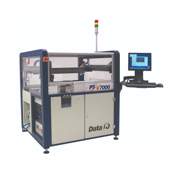
- Page 1 ’ ’ PERATOR ANUAL PERATOR ANUAL Automated Programming and Handling Machine Components pages 1, 2, 3 Run a Job page 15 Chart for ‘My Jobs’ page 70 Collecting Log Files page 77 096-0461-001G...
- Page 2 096-0461-001G March 2018 Data I/O has endeavored to ensure that the information in this document is accurate and complete. Data I/O assumes no liability for errors, or for any incidental, consequential, indirect, or special damages, including, without limitation, loss of use, loss or alteration of data, delays, or lost profits or savings, arising from the use of this document or the product which it accompanies.
-
Page 3: Table Of Contents
Finding Socket Adapter Part Numbers (FC) Installing Adapters and Actuators (FC) Adjusting the Actuator Plates (LumenX) Installing Adapters and Actuators (LumenX) Adjusting the Actuator Plates 6» Installing the Correct Probes Removing and Installing a Probe Data I/O • PSV7000 Operator’s Manual... - Page 4 Contents 7» If Laser Marking—Installing the Correct Rotor Tips 8» Turning PSV7000 System Power ON 9» Selecting a Job—Starting AH700 Indirectly Using TaskLink (FlashCORE programmers) Using LumenX Data Management Software (DMS) 10» (Optional) Preselecting Programmers 11» Setting Media and Options—the Setup Window...
-
Page 5: Psv7000 Machine Components
■ PSV7000 Machine Components ◘ PSV7000 Machine Components This Visual Index of PSV7000 features and subassemblies locates them on the machine and in this manual. E-Stops • page 10 Tape Input • page 22; Power Panel • page 3 and Vibratory Tube Media •... -
Page 6: Work Surface Components
This label color = Optional equipment The Power Panel ð Figure 2: Some features on the PSV7000 work surface— shown here with static trays and 11 programmers. The system can be configured with a reject tray or a reject bin or both except when 3D Inspection Model UX is installed. -
Page 7: Power Panel Components
Programmer Power only Network connection Serial Number AC power connection Main Pressure Regulator Main air inlet ïThe Big Picture, page 1 Figure 3: Rear View of PSV7000. For information on connecting the facilities, see the Owner’s Manual. PSV7000 Operator’s Manual —3—... -
Page 8: Programmer Overview
Programmer Overview LumenX Jobs for LumenX pro- grammers are created LumenX is Data I/O’s latest programmer at the time of this document. with LumenX Data Man- Each LumenX programmer requires one to two Actuator Plates and agement Software. one to eight Socket Adapters for the specific device package being programmed. -
Page 9: Flashcore
■ PSV7000 Machine Components ◘ Programmer Overview FlashCORE Jobs for FC program- FlashCORE III is a robust programming engine supplied in the mers are created with PS-Family of products. Each programmer requires an Actuator Plate and a Socket Adapter for the specific device package being pro- TaskLink Software. -
Page 10: Supported Integrated Circuits (Devices)
■ PSV7000 Machine Components Supported Integrated Circuits (Devices) • Flash Memory: NOR, NAND, MCP, MMC, e.MMC, SD, MoviNAND, For all available OneNAND, iNAND, Serial Flash, EEPROM, EPROM devices supported, • Microcontrollers see the Data I/O • Logic devices: website and click... -
Page 11: Operation
PSV7000 Owner’s Manual device. (096-0460...PDF is in C:\AH700 and also avail- PSV7000 is a programming and handling system for traditional and able on our Technical fine-pitched integrated circuits (devices). It accepts most all package Library on our website). types. The on-screen application that run PSV7000 is AH700. -
Page 12: Safety Messages And Precautions
CAUTION: This is a caution message! It calls your attention to potentially hazardous situations and practices that might damage equipment. Definition of a Cau- (The potential loss is not as serious as a warning.) tion. —8— Data I/O • 096-0461-001G... -
Page 13: Safety Symbols
— Collision Warning —Laser Hazard Warning — ADVERTENCIA de peligro del laser — Laser-Hazard Warning —Compressed Air Warning — ADVERTENCIA de aire comprimido — Druckluft-Warnung —Electrostatic Discharge Warning (ESD) — ADVERTENCIA de descarga electrostática — Elektrostatische Entladung Warnung PSV7000 Operator’s Manual —9—... -
Page 14: Safety Systems
Emergency Stop (E-Stop) Buttons Two large, red Emergency Stop buttons are located near the top of the PSV7000 System—one on front and one on the back of the machine. When an E-Stop button is pressed, the gantry stops moving immedi- ately. -
Page 15: Safety Doors And Interlocks
There should be • only be one operator and all others should stand clear, and • the operator closing the door should announce his actions. See the figure below. PSV7000 Operator’s Manual —11—... -
Page 16: Electrostatic Discharge
Operators should wear an antistatic wrist strap (Data I/O part number 440-0021-001) connected to one of the grounding connec- tions on the machine. The wrist strap should contain a 1–10 M-ohm current limiting resistor. - Page 17 Doing so could damage devices with fine-pitched leads. Vacuum tools use a squeezable air bladder for suction. There are a variety of models, sizes and tips. Some tips are replaceable. Figure 5: A Vacuum Tweezer: Data I/O PN 565-8000. PSV7000 Operator’s Manual —13—...
-
Page 18: General Precautions
Personal injury or equipment damage can occur if any safety systems are disabled. If you suspect that a safety feature is damaged or malfunctioning, stop using the machine immediately and contact Data I/O Customer Service or a local Data I/O approved service representative. •... -
Page 19: Running A Job On Psv7000
Make sure all assemblies needed for the target job, such as the machine, the program- Dual Tray Feeder, a Marking System or the Tape Output System, are installed on the PSV7000 Machine. Refer to Chapter 2- Set Up mers, optional equipment, of the Owner’s Manual for more information. - Page 20 Stopping the System on page 63. • Light Tower Interpretation on page 67. • (Optional) Changing Programmer Status on page • Turning PSV7000 System Power OFF on page 72. • (Optional) Operating the Dual Tray Feeder ‘EX’ on page —16— Data I/O • 096-0461-001G...
-
Page 21: 1" Checking The System
■ Running a Job on PSV7000 ◘ 1» Checking the System Before you set up for your job, check that: • All side panels and doors are closed and no one is working on the machine. PSV7000 Machines must •... -
Page 22: 2" Installing Input/Output Media
(If pin 1 orientation doesn’t match pin 1 that is set in the Package File it must be corrected). Pin 1 on Data I/O sockets is almost always toward the far side of the Socket Adapter (the back of the machine). - Page 23 ■ Running a Job on PSV7000 ◘ Installing Input/Output Media Standard Static Tray Orientation FOR TRAYS ORIENTED with the long side parallel to the Y-axis (standard configuration), orient the input and output trays with the Your system administrator beveled corner to the near right.
- Page 24 Operation ■ Running a Job on PSV7000 Figure 7: To install a tray, index it along the two rows of pins (circles). The chamfered corner for the input and output trays is at the front right corner (arrow). Output tray position shown.
-
Page 25: Vibration Tube Input Option-Loading
(If pin 1 orientation doesn’t match pin 1 that is set in the Package File it must be corrected). Pin 1 on Data I/O sockets is almost always toward the far side of the Socket Adapter (the back of the machine). -
Page 26: Installing The Tape Feeder Module Option
Installing the Tape Feeder Module Option PSV7000 can be configured with an optional Tape Feeder for input media. The Tape Feeder installs on the front of the machine. The left and right slots accommodate Tape Feeders (not the center slot). Safety... - Page 27 ■ Running a Job on PSV7000 ◘ Installing Input/Output Media Remove the two screws securing each small safety plate as applicable for your setup (3 mm hex key) and remove the plate(s). Refer to the figures above. Align the rail on the bottom of the feeder with the desired chan- nel on the PSV7000 base plate.
- Page 28 To remove the Tape Feeder communication The feeder Status lamp should light if the PSV7000 is on. cable, grasp the collar Install the device reel if it is not already. and pull out.
-
Page 29: Installing The Tape Take-Up Module Option
Install the correct size take-up reel. Figure 12: The Tape Take-up Module is installed. Checking the Tape Output Option Set up of the TM-50 Tape Output is described in the PSV7000 Owner’s Manual. When starting a job that uses Tape Output: Ensure there is an empty take-up reel on the take-up reel spin- dle. - Page 30 Operation ■ Running a Job on PSV7000 Ending a Run of Taped Devices When the batch size has been reached: If the EPD Sensor was used, in the Controller Setup Menu, select Mode, and then press 3 to disable it.
-
Page 31: 3" (Optional) Performing 3D Coplanarity Inspection
■ Running a Job on PSV7000 ◘ (Optional) Performing 3D Coplanarity Inspection 3» (Optional) Performing 3D Coplanarity Inspection For information not found here, refer to the PSV7000 Owner’s Manual, Chapter 3, 3D Coplanarity Option. There are two models of... - Page 32 Operation ■ Running a Job on PSV7000 Figure 14: The 3D Coplanarity Lead Inspection System with prism Reticle installed (arrow). The 3D UltrVim Model VX is shown. Note: Typical AH700 options are available such as the Ignore feature (on the...
-
Page 33: 4" (Optional) Set Up Other Equipment
■ Running a Job on PSV7000 ◘ (Optional) Set up Other Equipment 4» (Optional) Set up Other Equipment Set up any other equipment such as barcode scanning. (For more, see Setting Up Input and Output Media in Chapter 2 in the Owner’s Manual or see customer letters on our Website technical library.) -
Page 34: 5" Socket Adapters And Actuator Plates
Operation ■ Running a Job on PSV7000 5» Socket Adapters and Actuator Plates Data I/O recommends installing Socket Adapters before a job has been started (before the AH700 Software is started). However, PSV7000 power can be ON. Note: Neither Socket Adapters nor Actuator Plates are inter- changeable between FlashCORE III programmers and LumenX programmers. - Page 35 ■ Running a Job on PSV7000 ◘ Socket Adapters and Actuator Plates Figure 15: [Top] Footnotes dialog in TaskLink lists the Socket Adapter ID. [Bottom] LumenX displays Socket Adapter IDs on the main window (arrow) If AH700 has already been started, you can find the correct Socket...
-
Page 36: (Fc) Installing Adapters And Actuators
Operation ■ Running a Job on PSV7000 the front of the machine and should contain a 1 M-ohm to 10 M-ohm current limiting resistor. WARNING: Pinch hazard! SOCKET ACTUATORS CAN STILL MOVE UP AND DOWN WHEN THE SAFETY DOORS ARE OPEN AND EVEN WHEN THE E-STOP IS PUSHED—the air... - Page 37 ■ Running a Job on PSV7000 ◘ Socket Adapters and Actuator Plates programmer is between two others, one of the adjacent Actuator Plates must be in the down position (sockets open). Remove the Socket Adapter— 4a. Unscrew the two captive screws with a 4 mm hex key and open the Adapter Bracket.
-
Page 38: (Fc) Adjusting The Actuator Plates
Operation ■ Running a Job on PSV7000 Bottom side, HIC Figure 19: Special Actuation Plate for HIC (High Insertion Count) Adapters. View A: the three dots identify HIC Actuator Plates. View B: HIC bars have radii (arrows). (FC) Adjusting the Actuator Plates... -
Page 39: (Lumenx) Installing Adapters And Actuators
■ Running a Job on PSV7000 ◘ Socket Adapters and Actuator Plates (LumenX) Installing Adapters and Actuators Remove/Install Actuator Plates To install or change a Socket Adapter on a LumenX programmer: If a job is running, click Finish on the Run window and wait for the PNP head to empty the sockets, move to the Park position and stop. - Page 40 Operation ■ Running a Job on PSV7000 Note: Actuator bar adjustments may vary depending on loca- tion—the front half of the programmer or the far half. (LumenX) Remove/Install Socket Adapters CAUTION: Electrostatic discharge (ESD) hazard! Wear an ESD strap or discharge static against a common ground to prevent damage to Socket Adapters and devices.
-
Page 41: (Lumenx) Adjusting The Actuator Plates
■ Running a Job on PSV7000 ◘ Socket Adapters and Actuator Plates (LumenX) Adjusting the Actuator Plates To adjust the Actuator Plates (both types, standard and HIC): Requirements • Head is parked. • Actuator for the target programmer is in the UP position (sock- ets closed). -
Page 42: 6" Installing The Correct Probes
UltraVim 3D camera, the diffuser disk is white. Note: For tip sizes not listed, refer to the original manual that came with your PSV7000. The older tips can be used with the new holders. The following illustration shows the basic components of a nozzle assembly on a PSV7000 PnP head. - Page 43 ■ Running a Job on PSV7000 ◘ List of Steps to Start a Job Part O.D. RUBBER CUPS FOR 1.9mm SQUARE HOLDER Number (mm) 1.75 2880014001 Vacuum,Cup,1.75mm OD,For 1.9mm Tip,PSV 2.25 2880013001 Vacuum,Cup,2.25mm OD, For 1.9mm Tip,PSV 3.05 2880040130 Vacuum,Cup,3.05mm OD, For 1.9mm Tip,PSV...
- Page 44 Operation ■ Running a Job on PSV7000 Now select the appropriate Probe Tip/Cup Holder (based on your selection of the optimal rubber cup in Step 1 above; there are 2 available cup holders with different mounting squares: 1.9 or 2.7 mm). The following table lists the available cup holders along with their corresponding part numbers.
-
Page 45: Removing And Installing A Probe
■ Running a Job on PSV7000 ◘ List of Steps to Start a Job Removing and Installing a Probe CAUTION: Safety hazard! Possible personal injury from moving machinery. Always make sure that the PNP head is stopped in the Park or Tool position before opening any access doors. - Page 46 Operation ■ Running a Job on PSV7000 Safety Plates Figure 23: Safety plates have been moved out of the way. Figure 24: Push the PNP head assembly down for access to the probe. A flashlight will aid in seeing it better.
- Page 47 ■ Running a Job on PSV7000 ◘ List of Steps to Start a Job Fixed Aligning pin on Probe Holder Retaining Clip Pull (shown gold here) Probe Tip Pull Figure 25: If a Retaining Clip was used, remove it from the probe prior to pulling off the tip.
- Page 48 Operation ■ Running a Job on PSV7000 Removing the Probe Holder In some cases, when using a 3D Coplanarity Inspection System you may also need to remove and replace the probe tip holder. Tools Required: 1.5 mm hex key.
- Page 49 ■ Running a Job on PSV7000 ◘ List of Steps to Start a Job What’s the difference between the T HANGE command and the T command? moves the OOL COMMAND IN THE ANTRY WINDOW head to the Tool position near the front of the machine for easy access.
-
Page 50: 7" If Laser Marking-Installing The Correct Rotor Tips
Operation ■ Running a Job on PSV7000 7» If Laser Marking—Installing the Correct Rotor Tips For jobs that use the laser marking option, the rotor tip must be of adequate size for the vacuum to hold the device. Devices with flat bottoms such as QFP, TSOP, and SSOP require tip diameters smaller than the shortest edge of the device. - Page 51 ■ Running a Job on PSV7000 ◘ List of Steps to Start a Job Screw in the two new tips. Rotate the Laser rotor by hand to access the other two tips. Figure 29: The Laser rotor can be rotated by hand when the motor is disabled (or the machine power is OFF).
-
Page 52: 8" Turning Psv7000 System Power On
Make sure the air line is connected and turn the air pressure switch ON. Make sure the pressure indicator number is green. Note: Turning power ON does not start AH700 (the PSV7000 Application Software). Although the AH700 icon on the monitor can be double-clicked, the preferred way to start the application is by first starting TaskLink or LumenX DMS—see the next heading. -
Page 53: 9" Selecting A Job-Starting Ah700 Indirectly
■ Running a Job on PSV7000 ◘ List of Steps to Start a Job 9» Selecting a Job—Starting AH700 Indirectly TaskLink (TL) and LumenX Data Management Software (DMS) can both automatically start AH700 Application Software when Run is clicked. Only TL and LX are discussed here after the definitions. - Page 54 Operation ■ Running a Job on PSV7000 Figure 31: Select a Task and click Run to run a job on PSV7000. A Footnotes Dialog displays. Take note of the Socket Adapter and Actuator Plate part numbers required. Click OK to close the dialog.
-
Page 55: Using Lumenx Data Management Software (Dms)
■ Running a Job on PSV7000 ◘ List of Steps to Start a Job Using LumenX Data Management Software Double-click the LumenX DMS icon. Click your job name. If no jobs display, see the on-screen Help for pointing LumenX to the correct directory. - Page 56 Operation ■ Running a Job on PSV7000 Click Run. Both TaskLink and LumenX open AH700. LumenX must be in Mode for it to open AH700 Settings > Settings set Presenter Mode to PSV Mode Figure 36: The AH700 Main window opens with a job loaded and the job name displayed (arrow).
-
Page 57: 10" (Optional) Preselecting Programmers
■ Running a Job on PSV7000 ◘ List of Steps to Start a Job 10» (Optional) Preselecting Programmers PSV7000 can be configured with up to 24 FlashCORE programmers, or up to 14 LumenX programmers, or a mix of both, depending on other options installed. -
Page 58: 11" Setting Media And Options-The Setup Window
Operation ■ Running a Job on PSV7000 11» Setting Media and Options—the Setup Window For these steps refer to the Figure 37 on page 53 Figure 38 below. On the AH700 Main window, click Start. On the Options tab of the Setup window, select the desired Input, Output, and Reject media. -
Page 59: Verifying Media Setup
■ Running a Job on PSV7000 ◘ List of Steps to Start a Job 5a. (Optional) In the Continuity Retries field, enter the number of times the system should retry continuity failures before rejecting the device. 5b. (Optional) In the Fail Retries field, enter the number of... - Page 60 Operation ■ Running a Job on PSV7000 For more information Figure 39: The Job Info Tab is a read-only review of information, with about External Serializa- the exception of the Pass Limit field (and ESP SN field, if External tion see Comma Sepa- Serialization Program is used) which are editable.
-
Page 61: Aligning The Tape-Input Pick Point
■ Running a Job on PSV7000 ◘ List of Steps to Start a Job damaged. If you have any doubts about the Package File, con- tact your system administrator. Aligning the Tape-Input Pick Point If tape feeder input is used, align the pick point; see page 24 for more. -
Page 62: 12" Starting Programming
12» Starting Programming After setting up the machine hardware, input/output media and options, the job is ready to be run. Note: Prior to starting a job on PSV7000, make sure there are no devices in the programmers. See Removing Devices on page 63. -
Page 63: (Optional) View Of Laser Status
■ Running a Job on PSV7000 ◘ List of Steps to Start a Job Turn the Enable selector OFF. Turn Key selector ON. Turn Enable selector ON. Note: Depending on laser interlock status, the lamp may never turn solid RED, but blinking orange if the Laser cover is open or Laser rotor is not in marking position. -
Page 64: Starting The Fume Extractor (If Not Already)
If for some reason the Fume Extractor is not running, follow the steps below to turn the Fume Extractor power ON. To manually start the Laser Fume extractor, Turn the PSV7000 power is OFF. Refer to Turning PSV7000 Sys- tem Power OFF on page 72. -
Page 65: Programming Errors
■ Running a Job on PSV7000 ◘ Programming Errors Figure 43: Fume Extractor Power Switch (hidden behind hose). Close the access doors. Close the safety doors and turn the PSV7000 System power ON. Programming Errors Interpreting programming results can be done by understanding the AH700 Run window information and observing the LEDs on the Socket Adapters. -
Page 66: Programming Results Interpreted At The Socket
Operation ■ Running a Job on PSV7000 Figure 45: The numbers surrounding the programmer icons in the Run window; TOP—FlashCORE, BOTTOM—LumenX. Refer to the table below: (these numbers are examples only). Value: Indicates: Programmer 1 Programmer 9 Socket Adapter actuation count. If this number is red, the Socket Adapter lifetime actuation count has been exceeded. -
Page 67: Removing Devices
■ Running a Job on PSV7000 ◘ Removing Devices Removing Devices If unwanted devices are in programmer sockets, they can be removed in two ways: Manually Pause or Finish (end) a job. Right-click on the desired programmer to open a submenu, and then click Opener UP. -
Page 68: Emergency Stop
Operation ■ Running a Job on PSV7000 Note: Job throughput as displayed in the Run window is affected by the length of time a job is paused. Nominal throughput excludes paused time. Emergency Stop To prevent bodily injury or damage to equipment in an emergency, press the red Emergency Stop (E-Stop) button located on the front and back of the machine. -
Page 69: Pausing A Job
■ Running a Job on PSV7000 ◘ Stopping the System If it fails, then click Abort to close the AH700 application. Reselect the job in TaskLink or Job Runner and click Run. Pausing a Job To pause a job (stopping the Gantry) click Pause on the Run window. -
Page 70: Ending A Job
Operation ■ Running a Job on PSV7000 Ending a Job To end a job prior to programming the preset number of devices, click Finish on the Run Window. This completes the current programming cycle. No more blank devices are picked from the input media, and all devices in the sockets are removed and placed in the appropriate output or reject container. -
Page 71: Light Tower Interpretation
■ Light Tower Interpretation ◘ Stopping the System Light Tower Interpretation During operation of the PSV7000 System, you can monitor the light tower to reduce system down time. The light tower displays the fol- lowing conditions: Machine Light Condition... -
Page 72: Changing Programmer Status
Operation ■ Changing Programmer Status Changing Programmer Status PSV7000 may automatically disable a programmer for various rea- sons, for example, if there are repeated continuity errors or vacuum issues. The operator may also choose to disable a programmer, or otherwise change the status of a programmer. - Page 73 Figure 49: Right-click a programmer in the Run window to change the status of the programmer, toggle the vacuum, or perform various other functions. NOTE that “All => EMPTY” and “=>” EMPTY only change the status and do not empty the socket(s). PSV7000 Operator’s Manual —69—...
-
Page 74: My Jobs That Use The Same Setup
¨ Static Tray ¨ 3D Inspect VX ¨ Static Tray ¨ Auto Tray Fdr ¨ 3D Inspect UX ¨ Auto Tray Fdr • __________________ ¨ Vibratory Fdr ¨ Reject Type ¨ Vibratory Fdr _____________ • __________________ —70— Data I/O • 096-0461-001G... -
Page 75: Finishing A Job
Finishing a Job After a job completes: Wait for the PNP head to park. (Optional) If Sort-On-Error-Code was employed, record the num- ber of devices in Reject 1, (FailBox1). Empty the reject container(s). Remove programmed devices. PSV7000 Operator’s Manual —71—... -
Page 76: Turning Psv7000 System Power Off
Operation ■ Finishing a Job Turning PSV7000 System Power OFF When the PSV7000 System will not be run overnight, or before per- forming a service procedure, turn OFF the power. Finish or end the job if one is running. - Page 77 On/Off switches for the Tube Media WAIT UNTIL WINDOWS COMPLETES SHUTTING DOWN, Modules do not need then rotate the main power switch (on the PSV7000 Power Panel) to be turned OFF. counterclockwise to the OFF (vertical) position. Power is controlled (Optional) Padlock the main power switch so that it cannot be by the AH700 SW.
-
Page 78: Dual Tray Feeder
Operating the Dual Tray Feeder ‘EX’ As an option, the PSV7000 System can be configured with an Dual Tray Feeder. Only basic operation of the Data I/O Automatic Tray Feeder is described here. - Page 79 However, opening the Tray Feeder door will stop any tray movement until it is closed again. It does not stop PSV7000 operation unless a tray exchange is required while the Tray Feeder door is open.
-
Page 80: Additional Features
Data I/O offers several utilities that are especially useful to certain industries. These utilities, labeled the Automotive Performance Pak (AP Pak). If your PSV7000 System has this option and you want confirm input devices or generate labels, for instance, contact your adminis- trator. -
Page 81: If You Have Trouble
Start Collect PSV7000 Logs by clicking the windows Start button > Dataio > CollectLogs. (Optional) In Collect PSV7000 Logs, click Add Description. In Collect PSV7000 Logs, click Collect and ZIP and save the ZIP file to a desired folder. To send to Data I/O Support, 6a. -
Page 82: My Notes
Operation ■ My Notes My Notes —78— Data I/O • 096-0461-001G... -
Page 83: Index
I don’t see ‘Nautilus’ in here! It should be here. Let us know of any items you can’t find by e-mailing UserDocs@dataio.com Chart, My Jobs 70 Fail Retries 55 Checking system readiness 17 Feeder Unit, see Tape Feeder Clearing sockets 63, 69 Footnotes Dialog 50 Collect System logs 77 Components 1 Computers location 1 selecting 72 73 Gantry, for more see on‐screen Help Configuring input/output settings 54 Gantry, image 1 Contact Information, inside back cover Coplanarity inspection 27 Head submenu 45 Home position 11 PSV7000 Operator’s Manual —79—... - Page 84 FC 5 FlashCORE 4 LX 4 installing Socket Adapter 32 Light Tower locking configuration 53 colors 67 LumenX 4 description 67 LX LEDs 4 Log files 77 pre‐selecting 53 LumenX Data Management Software 49, 51 re‐enable 68 LumenX programmer 4, 49 Programming errors 61 Programming Results 62 PSV Mode (LumenX) 51 Mark devices only 55 My Jobs chart 70 Removing Actuator Plate 32 Socket Adapters, FC 33 Optional Equipment 18 Restart E‐Stop 64 Options tab 54 Restarting 64 Other documentation 29 Retries, programming 55 Output media 18, 54 Run window 58, 61, 65, 69 Owner’s Manual 7 numbers 61 Running a job 58 —80— Data I/O • 096-0461-001G...
- Page 85 Tray Feeder 74 Socket numbers Tube Feeder Run window 61 adjusting 22 Start programming 58 communication 21 Starting loading 21 a job 49 Tube Input/Output Modules a job, list of steps 15 power OFF 73 AH700 49 power ON 21 LumenX 49 setting up 21 TaskLink 49 Turning Off the System 72 starting 49 Turning Power Off 72 Static Tray Mount 19 Turning power On 48 Stopping Emergency Stop 64 end a job 66 pause programming 65 Stopping the system 63 Vibration Adjustment Controls 22 Switching between PCs 72 73 System log files 77 Work surface 2 Wrist strap connections 2 ohms 12 PSV7000 Owner’s Manual —81—...
- Page 86 Index ■ —82— Data I/O • 096-0461-001G...
-
Page 87: Technical Support
Telephone: inside US 1-800-332-8246 USA Fax: +1 425-867-6972 Contact Data I/O World Wide Support or your local representative. To find your local representative on our Web site, go to http://www.dataio.com and click Contact Sales (upper right), and then Representative Search . - Page 88 www.dataio.com www.dataio.de www.datio.cn...
Need help?
Do you have a question about the PSV7000 and is the answer not in the manual?
Questions and answers