Sign In
Upload
Manuals
Brands
Data I/O Manuals
Motherboard
UniSite-xpi
Data I/O UniSite-xpi Manuals
Manuals and User Guides for Data I/O UniSite-xpi. We have
1
Data I/O UniSite-xpi manual available for free PDF download: User Manual
Data I/O
UniSite-xpi
User Manual
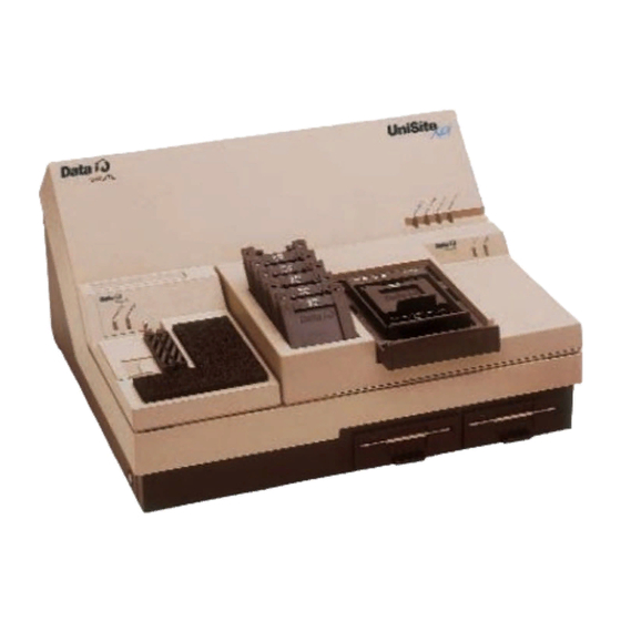
Data I/O UniSite-xpi User Manual (413 pages)
Brand:
Data I/O
| Category:
Motherboard
| Size: 4 MB
Table of Contents
Table of Contents
5
Safety Summary
15
Preface
17
Data I/O Customer Support
17
United States
17
Canada
17
Japan
18
Germany
18
Other Countries
18
Contacting Data I/O
19
Telephone
19
Fax
19
E-Mail
19
World Wide Web (Www.dataio.com)
19
Warranty Information
19
Keep Current Subscription Service
20
Repair Service
20
End User or Address Change
20
Introduction
21
Product Description
21
Standard Configuration
21
Options
21
Contents of Package
22
List of Figures
23
Unisite-Xpi External Features
23
The Front Panel
23
Figure 1-2 Front Panel Features
23
The Back Panel
24
Figure 1-3 Back Panel Features
24
Disks
25
Programmer Disks
25
PC Disk
25
Specifications
26
Safety
27
Electrostatic Discharge (ESD)
27
Electromagnetic Emissions
27
Certificate of RFI/EMI Compliance
27
Performance Verification
27
Options
28
How Many Pin Driver Boards Do You Need (Legacy)
30
Setup and Installation
32
Before You Begin
32
Licensing Agreement
32
Definitions
32
Install a Module
33
Removing the Blank Module Cover
33
Installing a Module
33
Removing a Module
34
Check the Line Voltage (on Older Units)
35
Choose Your Configuration
35
Hardware Choices
35
Software Choices
35
Figure 2-2 Unisite's Rear Panel
35
Connect Your Equipment
36
Connecting to a PC
36
Connecting to a Host
40
Connecting to a Terminal
41
Figure 2-4 Transparent Mode
42
More about Cables
45
Install the Base
45
Installing a Base
45
Removing a Base
46
Power up the Programmer
46
Connecting the Power Cord
47
Powering up
47
Figure 2-6 Front Panel Indicators
48
Figure 2-7 Tasklink Connection Established Message
51
The Power-On Screen for Terminal Mode
52
Selecting a New Terminal Type
52
Changing the Default Terminal
53
Insert Algorithm Disk
54
Unisite (Legacy)
54
Update System Software
54
Unisite-Xpi
54
Figure 2-9 Write-Enabled Disk
55
10. Set up High Speed Download
56
Why Should I Use High Speed Download
56
Configuring the Remote Port
56
Changing the Powerup Defaults
58
Using High Speed Download
58
Using the Mass Storage Module (Hard Drive)
59
Booting from the MSM
59
Storage Capacity
59
Storage Suggestions
59
Limitations
59
Backing up the MSM
60
Installing Hardware (Legacy)
60
Installing Software (Legacy)
60
12. Working with Devices
60
Inserting a DIP Device
60
Installing a Matchbook
61
Figure 2-12 Closing the Matchbook
62
Figure 2-11 Inserting a Matchbook into the Base
62
Inserting a PLCC or LCC Device into a Matchbook
63
Inserting an SOIC Device into a Matchbook
64
Figure 2-14 Inserting an SOIC Device
64
Removing a Device from a Matchbook
65
Inserting a PGA Device in a PGA Base
65
Inserting Devices into a PPI Adapter
66
Figure 2-16 TSOP Device Orientation
67
Figure 2-17 QFP Device Orientation
68
Maintenance
69
Changing the Line Voltage (Legacy)
69
Replacing the Line Fuse
70
Figure 2-20 Voltage Reading
70
Figure 2-21 Opening the Fuse Holder
70
Figure 2-22 Removing the Fuse Holder
70
What to Do Next Time
71
Figure 2-23 Removing the Fuse Holder
71
Getting Started
73
Before You Begin
73
Should I Read this Chapter
73
What will I Learn
74
Tasklink for Windows Mode (Serial and Parallel)
74
Tasklink for DOS Mode (Serial Only)
74
Hiterm (Terminal) Mode (Serial Only)
74
Outline of the Programming Operation
75
Tutorials for Tasklink for Windows Mode
76
Session 1: Selecting a Device
76
Figure 3-3 Programmer Type
76
Figure 3-4 System Menu: Simulation Mode
77
Session 2: Setting Programmer Properties
78
Figure 3-6 Select Device Dialog
78
Figure 3-7 Setup Menu: Programmer Properties
78
Figure 3-8 General Tab
79
Figure 3-9 Memory Tab
79
Session 3: Loading Data
80
Figure 3-10 Data Menu: Load RAM from Pc/Network File
80
Figure 3-11 Browsing for Data File
80
Session 4: Selecting Processes
81
Figure 3-13 Data File Loaded
81
Figure 3-15 Select Process
82
Session 5: Programming a Device
83
Figure 3-17 Process Devices
83
Figure 3-18 Waiting for Start
84
Figure 3-20 Tasklink Main Screen with Last Job Summary
85
Tutorials for Tasklink for DOS Mode
86
Session 6: Selecting a Device
86
Figure 3-22 Programmer Type
86
Figure 3-23 Setup Menu: Select Device
87
Figure 3-24 Select Manufacturer
87
Session 7: Setting Programmer Properties
88
Session 8: Loading Data
89
Figure 3-29 PC Disk File
90
Session 9: Selecting Processes
91
Session 10: Programming a Device
92
Figure 3-35 Statistics
93
Tutorials for Hiterm (Terminal) Mode
94
General Information about Hiterm
94
The Unisite-Xpi Screen
95
Moving the Cursor
96
Selecting a Command
96
Accessing Online Help
96
Figure 3-38 Areas of the Help Screen
97
Using Key Functions
98
Review of Programming Concepts
98
Session 11: Navigating through the Menus
99
Select a Menu Item
99
Select Online Help
100
Exit the Online Help
101
Review
101
Session 12: Selecting a Device
102
Before You Begin
102
Can I Use Another Device
102
Select a Manufacturer
102
Select a Device Part Number
104
Reviewing Your Options
104
Accessing Device-Specific Online Information
105
Review
105
Session 13: Selecting a Keep Current Algorithm
105
Before You Begin
105
Can I Use Another Device
106
Select the Keep Current Option
106
Figure 3-45 the Keep Current Part List
107
Select the Keep Current Algorithm
108
Keep Current Algorithms and Software Updates
108
Special Note
109
Session 14: Loading Data from a Device
110
Before You Begin
110
Can I Use Another Device
110
Select a Device
110
Insert the Device
111
Load the Data
111
Parameter Screens
112
Setting the Parameters
113
Loading the Data
113
Review
113
Session 15: Loading Data from Disk
114
Before You Begin
114
Getting There
114
Figure 3-49 the File Menu
115
Review
116
Session 16: Selecting a Translation Format
117
About Translation Formats
117
Getting There
117
Review
118
Session 17: Loading Data from a PC Using Hiterm
118
Before You Begin
118
What to Transfer
118
Figure 3-52 the Download Data from Host Screen
119
Downloading the File
120
After the Download
121
Review
121
Session 18: Loading Data from a Host
122
Before You Begin
122
What to Transfer
123
Downloading the File
124
After the Download
125
Review
125
Session 19: Editing Data
126
Before You Begin
126
Moving Around
127
Making Changes
127
Restoring Your File
128
Saving Your Edits
128
Review
128
Session 20: Programming a Memory Device
128
Before You Begin
128
Can I Use Another Device
129
Load the Data File
129
Parameter Screens
129
What Is the Difference
129
Programming the Device
130
Review
131
Session 21: Verifying a Device
131
Before You Begin
131
Can I Use Another Device
131
Parameter Screens
131
Setting the Verify Parameters
132
Verifying the Device
133
Review
133
Commands
135
Menu Organization
135
Menu Maps
135
Figure 4-1 the Command Tree
136
Overwriting User RAM
137
Factory Default Settings
137
Select Device
139
Before You Select a Device
139
Selecting a Device
140
After You Select a Device
141
Cross Programming
142
Quick Copy
143
Load Device
144
Load Logic Device
144
Load Memory Device
145
Program Device
147
Program Logic Device
147
Program Memory Device
150
Enhanced Security Fuse Capability
153
Verify Device
154
Verify Logic Device
154
Verify Memory Device
155
More Commands
158
Configure System
159
Programmer ID
174
Carrying a Configuration File Forward
174
Keep Current
177
Custom Menu Algs
180
Mass Storage
186
Device Checks
187
Edit Data
196
File Operations
207
Job File
214
Remote Control
216
Self-Test
216
Transfer Data
217
Yield Tally
227
Computer Remote Control
229
Which Driver to Use
229
System Setup
230
Entering CRC Mode
230
Exiting CRC Mode
231
Halting CRC Operations
232
CRC Default Settings
233
CRC Commands
234
Translation Formats
239
Instrument Control Codes
241
General Notes
242
ASCII Binary Format, Codes 01, 02, and 03(or 05, 06, and 07)
243
Texas Instruments SDSMAC Format (320), Code 04
245
The 5-Level BNPF Format, Codes 08 or 09
247
Formatted Binary Format, Code 10
248
DEC Binary Format, Code 11
249
Spectrum Format, Codes 12 or 13
250
POF (Programmer Object File) Format, Code 14
251
Absolute Binary Format, Code 16
254
LOF Format, Code 17
255
LOF Field Syntax
255
ASCII Octal and Hex Formats, Codes 30-37 and 50-58
257
RCA Cosmac Format, Code 70
259
Fairchild Fairbug, Code 80
260
MOS Technology Format, Code 81
261
Motorola Exorciser Format, Code 82
262
Intel Intellec 8/MDS Format, Code 83
263
Signetics Absolute Object Format, Code 85
264
Tektronix Hexadecimal Format, Code 86
265
Motorola Exormacs Format, Code 87
266
Intel MCS-86 Hexadecimal Object, Code 88
267
Hewlett-Packard 64000 Absolute Format, Code 89
269
Texas Instruments SDSMAC Format, Code 90
271
JEDEC Format, Codes 91 and 92
273
Introduction
273
BNF Rules and Standard Definitions
273
JEDEC Full Format, Code 91
276
JEDEC Field Syntax
277
Field Identifiers
277
JEDEC U and E Fields
280
JEDEC Kernel Mode, Code 92
284
Extended Tektronix Hexadecimal Format, Code 94
285
Motorola 32-Bit Format, Code 95
287
Hewlett-Packard UNIX Format, Code 96
288
Figure 6-22 Hewlett-Packard 64000 Unix Format
289
Intel OMF386 Format, Code 97
290
Intel OMF286 Format, Code 98
291
Figure 6-24 a Close-Up of the Intel OMF286 Format
292
Intel Hex-32, Code 99
293
Highest I/O Addresses
295
Messages
297
Troubleshooting Guides
335
Device Insertion Error When Using Elastomeric Pad
336
Device Over-Current Fault
338
Device Programming Error
340
Invalid Device ID on Logic Device
341
Electronic ID Verify Error on Memory Device
342
Illegal Bit Error
344
I/O Timeout Error
346
Partial or no Transfer Performed
347
Incompatible User Data File for Device Selected
348
Glossary
349
Using Modules
362
Introduction to Pinsite
362
Configuration
362
Compatibility
363
Pin Driver Requirements
363
Installing the Pinsite Module
364
Installing the Pinsite Module in Unisite-Xpi
364
Installing a Base in Pinsite
365
Figure A-4 Base Receptacle Opening
366
Figure A-5 Aligning the Base
367
Installing a Matchbook in a Base
368
Figure A-7 Inserting a Matchbook into a Base
369
Installing a PLCC or LCC Device in a Matchbook
370
Installing an SOIC Device in a Matchbook
371
Figure A-10 SOIC Device Insertion
372
Installing a PGA Device in a PGA Base
373
Using the PPI Base
374
Installing a PPI Adapter into the PPI Base
374
Figure A-12 PPI Base
375
Figure A-14 Lowering the Base Door over the Adapter
376
Figure A-16 Removing the Door from PPI Base
377
Installing Devices into a PPI Adapter
378
Figure A-19 QFP Device Orientation
379
Using Pinsite
380
Conductive Pad Care
380
Introduction to Setsite (Legacy
381
Compatibility
381
(Legacy) Compatibility
381
Features
382
Using Setsite (Legacy
384
Selecting Setsite
384
Setsite Screens
384
(Legacy) Selecting Setsite
384
(Legacy) Setsite Screens
384
Set and Gang Programming
385
(Legacy) Set and Gang Programming
385
Setsite Applications (Legacy
386
Gang Programming
386
(Legacy) Gang Programming
386
Gang Programming
387
Set Programming
388
(Legacy) Set Programming
388
Programming Partial Sets of Devices
390
(Legacy) Programming Partial Sets of Devices
390
Preventive Maintenance for Modules (Legacy
391
Error Conditions
391
SPA Block
391
Bases
392
Conductive Pad
392
Making Your Own Cable
393
Overview
393
Smartport
393
Making Your Own Cable
394
Switching Modes
395
Keep Current Subscription Service
397
Procedure Overview
398
Gather Device Information
399
Connect to the Data I/O Web Site
399
Find Algorithm
399
Download and Expand Algorithm
400
Use Algorithm
400
Sample Keep Current Scenario
401
Advertisement
Advertisement
Related Products
Data I/O 298
Data I/O 29B
Data I/O FLX500
Data I/O PSV7000
Data I/O Categories
Motherboard
Control Systems
Industrial Electrical
More Data I/O Manuals
Login
Sign In
OR
Sign in with Facebook
Sign in with Google
Upload manual
Upload from disk
Upload from URL