Table of Contents
Advertisement
Quick Links
Download this manual
See also:
User Manual
Advertisement
Table of Contents

Related Manuals for Kontron CP3003-SA


Summary of Contents for Kontron CP3003-SA
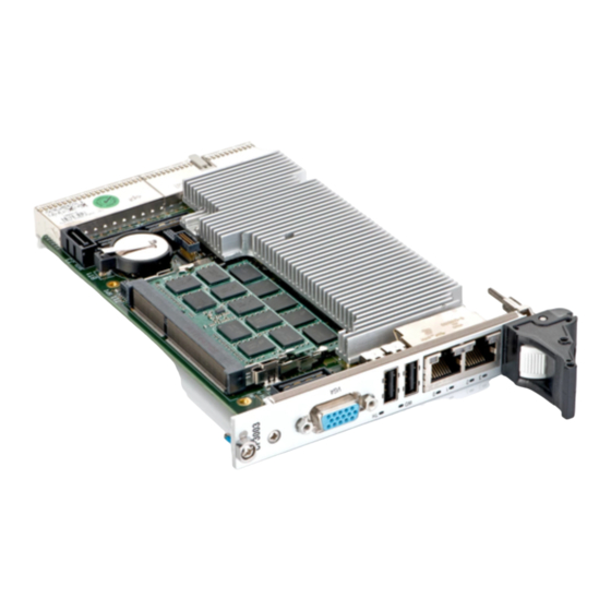
- Page 1 » User Guide « CP3003-SA 3U CompactPCI Processor Board based on the 3 Generation Intel® Core™ i7 Processor with the Intel® QM77 Chipset Doc. ID: 1052-6929, Rev. 1.0 November 14, 2012 If it’s embedded, it’s Kontron.
-
Page 2: Imprint
Disclaimer Copyright © 2012 Kontron AG. All rights reserved. All data is for information purposes only and not guaranteed for legal purposes. Information has been carefully checked and is believed to be accurate; however, no responsibility is assumed for inaccuracies. Kontron and the Kontron logo and all other trademarks or registered trademarks are the property of their respective own- ers and are recognized. -
Page 3: Table Of Contents
CP3003-SA Preface Table of Contents Revision History ......................ii Imprint ........................ii Disclaimer ........................ii Table of Contents ...................... iii List of Tables ......................ix List of Figures ......................xiii Proprietary Note .......................xv Trademarks ......................xv Environmental Protection Statement ................xv Explanation of Symbols ..................xvi For Your Safety ...................... - Page 4 Preface CP3003-SA Functional Description ............2 - 3 2.1 Processor ....................2 - 3 2.2 Memory ....................2 - 4 2.3 Intel® QM77 Express Chipset ..............2 - 5 2.4 Timer ......................2 - 5 2.5 Watchdog Timer ..................2 - 5 2.6 Battery .....................2 - 6 2.7 Reset .......................2 - 6...
- Page 5 3.3 Standard Removal Procedures ............... 3 - 5 3.4 Insertion/Removal under Power ............. 3 - 6 3.4.1 Replacement under Power in Peripheral Slot ......... 3 - 6 3.5 Installation of CP3003-SA Peripheral Devices ........3 - 8 3.5.1 USB Device Installation ..............3 - 11 3.5.2 Installation of External SATA Devices ...........
- Page 6 5.1.3.4 Regulation ................5 - 5 5.2 Power Consumption ................5 - 6 5.3 Power Consumption of CP3003-SA Accessories ........5 - 8 5.4 Maximum Power Consumption of XMC Modules ........5 - 8 Thermal Considerations ............6 - 3 6.1 Board Internal Thermal Monitoring ............6 - 3 6.2 Processor Thermal Monitoring ..............6 - 3...
- Page 7 B.2 Technical Specifications ................B - 3 B.3 CP3003-XMC Module Functional Block Diagram ........B - 4 B.4 Front Panel of the 8 HP CP3003-SA with CP3003-XMC Module ...B - 5 B.5 CP3003-XMC Module Layout ..............B - 6 B.6 Module Interfaces (Onboard) ..............B - 7 B.6.1...
- Page 8 Preface CP3003-SA C. CP-RIO3-04 Rear I/O Module ..........C - 3 C.1 Overview ....................C - 3 C.2 Technical Specifications ................. C - 3 C.3 Front Panels ................... C - 4 C.4 Module Layout: 4 HP and 8 HP Versions ..........C - 5 C.5 Module Interfaces ...................
-
Page 9: List Of Tables
2-12 CompactPCI Connector J1 System Controller Slot Pinout ...... 2 - 18 2-13 CompactPCI Connector J1 Peripheral Slot Pinout ........2 - 19 2-14 64-bit CompactPCI Connector J2 Pinout (CP3003-SA Front I/O Vers.) .. 2 - 20 2-15 Rear I/O CompactPCI Connector J2 Pinout (CP3003-SA Rear I/O Vers.).. 2 - 22 2-17 GPIO Signal Description ................ - Page 10 Input Voltage Characteristics ..............5 - 5 CP3003-SA in EFI Shell ................5 - 7 CP3003-SA with Win. 7 and Processor and Graphics in Idle State ... 5 - 7 CP3003-SA with Win. 7 and Max. Proc. Workload and Basic Graph. Oper. 5 - 7 CP3003-SA with Win.
- Page 11 CP3003-SA Preface C-1 CP-RIO3-04 Rear I/O Module Main Specifications ........C - 3 C-2 USB Con. J11 and J12 Pinout ..............C - 6 C-3 D-Sub VGA Connector J7 Pinout .............. C - 6 C-4 Dual Gigabit Ethernet Connector J10A/B Pinout ........C - 7 C-5 COM Connectors J2a (COMA) and J3a (COMB) Pinout ......
- Page 12 Preface CP3003-SA This page has been intentionally left blank. Page xii ID 1052-6929, Rev. 1.0...
-
Page 13: List Of Figures
CP3003-SA with i7-3517UE (ULV), 1.7 GHz ........... 6 - 7 CP3003-HDD Module Functional Block Diagram ........A - 5 Front Panel of the 8 HP and 12 HP CP3003-SA with CP3003-HDD Mod. A - 6 CP3003-HDD Module Layout for 8 HP Board Version (Top View) ... A - 7 CP3003-HDD Module Layout for 12 HP Board Version (Top View) .. - Page 14 A-11 SATA Connector J6/J2 ................A - 13 CP3003-XMC Module Functional Block Diagram ........B - 4 Front Panel of the 8 HP CP3003-SA with CP3003-XMC Module ... B - 5 CP3003-XMC Module Layout (Top View) ..........B - 6 CP3003-XMC Module Layout (Bottom View) ..........
-
Page 15: Proprietary Note
Kontron without further notice. Trademarks Kontron, the PEP logo and, if occurring in this manual, “CXM” are trademarks owned by Kontron, Kaufbeuren (Germany). In addition, this document may include names, company logos and trademarks, which are registered trademarks and, therefore, proprietary to their respective owners. -
Page 16: Explanation Of Symbols
Preface CP3003-SA Explanation of Symbols Caution, Electric Shock! This symbol and title warn of hazards due to electrical shocks (> 60V) when touching products or parts of them. Failure to observe the pre- cautions indicated and/or prescribed by the law may endanger your life/health and/or result in damage to your material. -
Page 17: For Your Safety
However, the life expectancy of your product can be drastically reduced by improper treatment during unpacking and installation. Therefore, in the interest of your own safety and of the correct operation of your new Kontron product, you are requested to conform with the following guidelines. -
Page 18: General Instructions On Usage
CP3003-SA General Instructions on Usage In order to maintain Kontron’s product warranty, this product must not be altered or modified in any way. Changes or modifications to the device, which are not explicitly approved by Kontron and described in this manual or received from Kontron’s Technical Support as a special handling instruction, will void your warranty. -
Page 19: Two Year Warranty
As a result, the products are sold “as is,” and the responsibility to ensure their suitability for any given task remains that of the purchaser. In no event will Kontron be liable for direct, indirect or consequential damages resulting from the use of our hardware or software products, or documentation, even if Kontron were advised of the possibility of such claims prior to the purchase of the product or during any period since the date of its purchase. - Page 20 Preface CP3003-SA This page has been intentionally left blank. Page xx ID 1052-6929, Rev. 1.0...
-
Page 21: Introduction
CP3003-SA Introduction Chapter Introduction ID 1052-6929, Rev. 1.0 Page 1 - 1... - Page 22 Introduction CP3003-SA This page has been intentionally left blank. Page 1 - 2 ID 1052-6929, Rev. 1.0...
-
Page 23: Board Overview
SATA interfaces, four USB 2.0 ports, one USB 3.0 port, two DisplayPort interfaces, and one x8 PCI Express 2.0 XMC interface. The CP3003-SA provides support for one 8 HP I/O exten- sion module such as the CP3003-HDD or the CP3003-XMC as well as one rear I/O module such as the CP-RIO3-04. -
Page 24: Hp Extension Module
Introduction CP3003-SA Some of the CP3003-SA's outstanding features include: • Support for the following 3 generation processors: • Intel® Core™ i7-3612QE (SV) quad-core processor, 2.1 GHz, 6 MB L3 cache • Intel® Core™ i7-3555LE (LV) dual-core processor, 2.5 GHz, 4 MB L3 cache •... -
Page 25: System Expansion Capabilities
1.3.4 SATA Flash Module The 4 HP CP3003-SA provides support for up to 32 GB of SLC NAND flash memory in combi- nation with an optional SATA Flash module, which is connected to an onboard connector. For further information concerning the SATA Flash module, refer to Appendix D. -
Page 26: Functional Block Diagram
Introduction CP3003-SA 1.4.1 Functional Block Diagram Figure 1-1: CP3003-SA Functional Block Diagram Page 1 - 6 ID 1052-6929, Rev. 1.0... -
Page 27: Front Panel
GbE B Note ... For information regarding the front panel of the 8 HP or 12 HP CP3003-SA with a CP3003-HDD module, refer to Appendix A, CP3003-HDD Module. For information regarding the front panel of the 8 HP CP3003-SA with a CP3003-XMC module, refer to Appendix B, CP3003-XMC Module. -
Page 28: Board Layout
Introduction CP3003-SA 1.4.3 Board Layout Figure 1-3: 4 HP CP3003-SA Board Layout (Top View) DDR3 SODIMM Sockets Ch. A Ch. B Memory Modules SATA Flash Module Smart Intel ® Core ™ i7 Extension Module Intel ® QM77 GbE A Proce ssor... -
Page 29: Technical Specification
Up to 32 GB SLC NAND flash via an onboard SATA Flash module (SSD) • Serial EEPROM with 64 kbit Intel® QM77 Mobile Intel® QM77 Express Chipset features used on the CP3003-SA: Four x1 PCI Express 2.0 ports operating at 5 GT/s • SATA host controller with six ports and RAID 0/1/5/10 support •... -
Page 30: Gigabit Ethernet
Support for up to seven peripheral slots (7x REQ/GNT signals) • When installed in a peripheral slot, the CP3003-SA is isolated from the Com- pactPCI bus. It receives power from the backplane and supports rear I/O. CP3003-SA removal under power:... - Page 31 I/O expansion to 8 HP board version via the CP3003-XMC module: PCI Express x8, x4 or x1 • CFast (SATA 3 Gb/s) • I/O expansion of CP3003-SA via the Smart Extension Module (exceeds 4 HP): SATA 3 Gb/s • USB 2.0 •...
-
Page 32: Digital Thermal Sensor (Dts)
Introduction CP3003-SA Table 1-1: CP3003-SA Main Specifications (Continued) FEATURES SPECIFICATIONS Front Panel Connectors VGA: 15-pin D-Sub connector, J4 • USB: two 4-pin, type A connectors, J5 and J6 • Ethernet: dual RJ-45 connector, J7A/B • Onboard Connectors 7-pin, L-form standard SATA connector, J3 •... -
Page 33: Power Consumption
If a Smart Extension Module is installed on the CP3003-SA, the board exceeds 4 HP. Board Weight 313 grams (4 HP CP3003-SA with heat sink, front panel, two 2 GB SODIMM memory modules, and battery but without SATA Flash module or without Smart Extension Module respectively) Note ... -
Page 34: Standards
Customers desiring to perform further environmental testing of Kontron prod- ucts must contact Kontron for assistance prior to performing any such testing. This is necessary, as it is possible that environmental testing can be destructive when not performed in accordance with the applicable specifications. -
Page 35: Related Publications
ANSI/VITA 42.3-2006 XMC PCI Express Protocol Layer Standard DisplayPort VESA DisplayPort Standard Version 1.1a Platform Firmware Unified Extensible Firmware Interface (uEFI) specification, version 2.1 All Kontron products Product Safety and Implementation Guide, ID 1021-9142 ID 1052-6929, Rev. 1.0 Page 1 - 15... - Page 36 Introduction CP3003-SA This page has been intentionally left blank. Page 1 - 16 ID 1052-6929, Rev. 1.0...
Need help?
Do you have a question about the CP3003-SA and is the answer not in the manual?
Questions and answers