
Related Manuals for Festo CTEU-PB


Summary of Contents for Festo CTEU-PB
- Page 1 Universal bus node CTEU-PB Electronics description Bus nodes Type CTEU-PB Fieldbus protocol PROFIBUS-DP Description 575393 en 1208NH [758863]...
- Page 3 ........575393 © (Festo AG & Co. KG, D-73726 Esslingen, 2012) Internet: http://www.festo.com E-Mail: service_international@festo.com...
- Page 4 Contents and general safety instructions ® ® ® ® ® PROFIBUS , SIMATIC , TORX , TÜV and VDE are registered trademarks of the respec- tive trademark owners in certain countries. Festo P.BE-CTEU-PB-OP+MAINT-EN en 1208NH English...
-
Page 5: Table Of Contents
........Festo P.BE-CTEU-PB-OP+MAINT-EN en 1208NH English... - Page 6 ........2-44 Festo P.BE-CTEU-PB-OP+MAINT-EN en 1208NH English...
- Page 7 ......4.1.6 Read out diagnostic messages via controller ....Festo P.BE-CTEU-PB-OP+MAINT-EN en 1208NH English...
- Page 8 ............Festo P.BE-CTEU-PB-OP+MAINT-EN en 1208NH English...
-
Page 9: Intended Use
Contents and general safety instructions Intended use The bus node CTEU-PB documented in this description has been designed exclusively for use as a station (slave) on the PROFIBUS-DP fieldbus. The bus node may only be used as follows: – as intended –... -
Page 10: Target Group
(PLCs) and participants on the PROFIBUS-DP fieldbus. Service Please consult your local Festo Service if you have any tech- nical problems. Instructions on this description This description includes specific information about the con-... -
Page 11: Important User Instructions
... means that failure to observe this instruction may result in material damage. In addition, the following pictogram marks passages in the text which describe activities with electrostatically sensitive devices: Electrostatically sensitive devices: Incorrect handling may cause damage to devices. Festo P.BE-CTEU-PB-OP+MAINT-EN en 1208NH English... - Page 12 Recommendations, tips and references to other information sources. Accessories: Specifications on necessary or useful accessories for the Festo product. Environment: Information on the environmentally friendly use of Festo products. Text designations Bullet points denote activities that may be carried out in • any sequence.
- Page 13 ‘Identification and Maintenance’ and represents the electronic I & M name plate of the bus node. Load voltage includes the power supply for connected devices and (digital) outputs, e.g. solenoid coils of valves Festo P.BE-CTEU-PB-OP+MAINT-EN en 1208NH English...
- Page 14 SYNC command. A SYNC command is cancelled with UNSYNC. Tab. 0/1: Terms and abbreviations Festo P.BE-CTEU-PB-OP+MAINT-EN en 1208NH English...
-
Page 15: Installation
Installation Chapter 1 Installation Festo P.BE-CTEU-PB-OP+MAINT-EN en 1208NH English... - Page 16 ......... . 1-21 Festo P.BE-CTEU-PB-OP+MAINT-EN en 1208NH English...
-
Page 17: General Instructions On Installation
– undefined switching states of the electronics Caution The bus node includes electrostatically sensitive devices. Do not touch any electronic components. • Observe the handling specifications for electrostatically • sensitive devices. They will help you avoid damage to the electronics. Festo P.BE-CTEU-PB-OP+MAINT-EN en 1208NH English... - Page 18 1. Installation Note Use protective caps or blanking plugs to seal unused con- nections. You will then achieve protection class IP65. Festo P.BE-CTEU-PB-OP+MAINT-EN en 1208NH English...
-
Page 19: Mounting
CAPC-... can be found in the assembly instructions that accompany the connec- tion box. Mounting on valve terminal For mounting the bus node, a valve terminal from Festo with I-port connection is required. Proceed as follows: 1. -
Page 20: Connection And Display Components
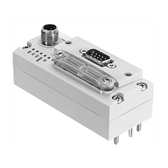
DIL switch group 1 and 2 and connected devices, if applicable Status LEDs (status display/dia- (e.g. valve terminal) gnostics chap. 3.2) Fieldbus connection (D-sub plug) Fig. 1/1: Connection and display components on the bus node Festo P.BE-CTEU-PB-OP+MAINT-EN en 1208NH English... -
Page 21: Power Supply
General requirements). 1.3.1 Power supply connection Interface specifications The bus node is equipped with a power supply connection in accordance with IEC 61076-2-101: – Round plug connector M12 – Plug (male) – A coded – 5-pin Festo P.BE-CTEU-PB-OP+MAINT-EN en 1208NH English... - Page 22 Tab. 1/1: Pin allocation of the power supply For the connection to power supply units or the power supply, use cables with M12 coupling (socket plug connector), A-coded, in accordance with IEC 61076-2 Accessories www.festo.com/catalogue). Festo P.BE-CTEU-PB-OP+MAINT-EN en 1208NH English...
-
Page 23: Setting The Dil Switches
1. Place the cover carefully on the bus node. Note Make sure that the seal is seated correctly! • 2. Tighten the two mounting screws at first hand-tight and then with a max. torque of 0.4 Nm. Festo P.BE-CTEU-PB-OP+MAINT-EN en 1208NH English... -
Page 24: Setting The Dil Switches
1 … 7: station ad- dress DIL switches 8 … 10: reserved (standard setting: OFF) DIL switch 11: diagnostics mode DIL switch 12: Fail state mode Fig. 1/2: DIL switch groups in the bus node 1-10 Festo P.BE-CTEU-PB-OP+MAINT-EN en 1208NH English... - Page 25 Station address examples Station address “5” DIL switch setting at the bus node Binary notation Binary number Decimal number = 1 + 4 = 5 Fig. 1/3: Station address coding, example 1 1-11 Festo P.BE-CTEU-PB-OP+MAINT-EN en 1208NH English...
- Page 26 You set the Fail state behaviour of the bus node with the switch element 12 (Fig. 1/2, item ) of the DIL switch groups. Constellations of Fail state behaviour can be found in chap. 2.8. 1-12 Festo P.BE-CTEU-PB-OP+MAINT-EN en 1208NH English...
-
Page 27: Connecting The Fieldbus
Also observe the corresponding regulations in EN 60204 Part 1. 1.5.2 Cable specifications For fieldbus communication, use a twisted, screened two-wire cable in accordance with the PROFIBUS specification (EN 50170, cable type A): 1-13 Festo P.BE-CTEU-PB-OP+MAINT-EN en 1208NH English... -
Page 28: Fieldbus Baud Rate And Fieldbus Length
Max. 500 m 19.2 kBaud Max. 1200 m Max. 500 m 93.75 kBaud Max. 1200 m Max. 100 m 187.5 kBaud Max. 1000 m Max. 33.3 m 500 kBaud Max. 400 m Max. 20 m 1-14 Festo P.BE-CTEU-PB-OP+MAINT-EN en 1208NH English... -
Page 29: Fieldbus Interface At The Bus Node
Connect the bus node with the fieldbus plug from Festo type FBS-SUB-9-GS-DP-B. Note Before connecting the sub-D plugs of other manufacturers: Replace the two flat screws with bolts • (type UNC 4-40/M3x5) from Festo accessories Accessories www.festo.com/catalogue). 1-15 Festo P.BE-CTEU-PB-OP+MAINT-EN en 1208NH English... -
Page 30: Connection Technology For Fieldbus Interface
You will then achieve protection class IP65. Connection with fieldbus plugs from Festo With a fieldbus plug, you connect the bus node conveniently to the fieldbus without the use of pre-made cable. Use the fieldbus plug, type FBS-SUB-9-GS-DP-B from the Festo accessories ( Accessories www.festo.com/catalogue). - Page 31 Clamp strap for screened connec- tion Fieldbus incom- ing (IN) Switch for bus terminal and con- tinuing fieldbus Fieldbus contin- ued (OUT) Only capacitively connected Fig. 1/5: Fieldbus plug from Festo, type FBS-SUB-9-GS-DP-B 1-17 Festo P.BE-CTEU-PB-OP+MAINT-EN en 1208NH English...
- Page 32 1. Installation Note The clamp strap in the fieldbus plug from Festo is connec- ted internally only capacitively with the metal housing of the Sub-D plug. This is to prevent compensating currents flowing through the screening of the fieldbus line.
- Page 33 Siemens Optical Link Module (OLM) for PROFIBUS plus – Siemens Optical Link Plug (OLP) for PROFIBUS (IP 20) ® – Harting Han-InduNet media converter IP 65 (optical data transmission in the DESINA installation concept) 1-19 Festo P.BE-CTEU-PB-OP+MAINT-EN en 1208NH English...
-
Page 34: Bus Terminal
Fig. 1/6: Circuit diagram of a bus terminal network in accordance with EN 50170 Recommendation: Use the fieldbus plugs from Festo for the bus terminal (see Fig. 1/5). A bus terminal network that can be connected and disconnected is integrated in the housing of this plug. -
Page 35: Functional Test
The LEDs X1 and/or X2 illuminate green when a device is connected. Check for error-free communication between bus node and master using the status LEDs: – The LED BF is not illuminated in the normal operating status. See also chap. 2.9.4, Normal operating status. 1-21 Festo P.BE-CTEU-PB-OP+MAINT-EN en 1208NH English... - Page 36 1. Installation 1-22 Festo P.BE-CTEU-PB-OP+MAINT-EN en 1208NH English...
-
Page 37: Commissioning
Commissioning Chapter 2 Commissioning Festo P.BE-CTEU-PB-OP+MAINT-EN en 1208NH English... - Page 38 ..........2-40 Festo P.BE-CTEU-PB-OP+MAINT-EN en 1208NH English...
- Page 39 ........2-44 Festo P.BE-CTEU-PB-OP+MAINT-EN en 1208NH English...
-
Page 40: General Remarks On The Fieldbus Protocol Profibus-Dp
PROFIBUS-DP fieldbus net- work. 2.1.1 Components Higher-order con- troller (DP master): e.g. from SIEMENS Fieldbus level: bus node CTEU Device level: e.g. valve termin- al VTUB-12 Drive level: e.g. Linear mo- dule HME Festo P.BE-CTEU-PB-OP+MAINT-EN en 1208NH English... -
Page 41: Data Exchange With The Profibus-Dp Fieldbus Protocol
US-DP standard. The method of accessing these commands depends on the controller used. Corresponding information can be found in your controller’s documentation. Information on DPV1 commands can be found in chap. A.2 in Appendix A. Festo P.BE-CTEU-PB-OP+MAINT-EN en 1208NH English... - Page 42 With each further SYNC command, the updated output image is transmitted. Reset Return to normal operation: UNSYNC command CLEAR_DATA command All output signals of the bus node are reset. Festo P.BE-CTEU-PB-OP+MAINT-EN en 1208NH English...
-
Page 43: Modules/Devices At I-Port Connection 1 And
2.2.2 Modules/devices at I-Port connection 1 and 2 Enter the identifiers corresponding to the physical sequence of the modules in your configuration program, starting with the device at I-Port connection 1, followed by the device at I-Port connection 2. Festo P.BE-CTEU-PB-OP+MAINT-EN en 1208NH English... - Page 44 PTL-16 (18 used I) VTUG-Interlock 1-16 valves with I-Port con- nection Valve terminal VAEM-L2-S_ 0x33 32DX 4 bytes / 4 bytes/32 O VTOC-Interlock / PTL-32 (18 used I) VTUG-Interlock 17-32 valves with I-Port con- nection Festo P.BE-CTEU-PB-OP+MAINT-EN en 1208NH English...
- Page 45 8 bytes / 64 O 64 outputs module 64DO Module identifier in the hardware configuration of the programming software Tab. 2/1: Module overview and address allocation: bus nodes and examples for digital input and output modules Festo P.BE-CTEU-PB-OP+MAINT-EN en 1208NH English...
-
Page 46: Installation On A Higher-Level Controller
The GSD includes all required information for adjustment of the bus node using configuration and programming software, e.g. Siemens SIMATIC STEP 7. Procurement source Current GSD and symbol files can be found on the Festo web- site at www.festo.com Support/Downloads Search “GSD”. - Page 47 GSD file to ensure support of all functions of the bus node. Installation Install the files by using the configuration software of your master controller. Please refer to the product documentation of your software for detailed procedures. 2-11 Festo P.BE-CTEU-PB-OP+MAINT-EN en 1208NH English...
-
Page 48: Configuration By Using Process Data
MPA-L and input module CTSL-… Bus node CTEU-PB Valve terminal MPA-L with I-Port con- nection Electrical connection box CAPC-... Input module CTSL-… Fig. 2/1: Configuration example 1: Bus node with devices at I-Port connection 1 and 2 2-12 Festo P.BE-CTEU-PB-OP+MAINT-EN en 1208NH English... - Page 49 4 bytes / 32 O IPO32 Input module CTSL-… CTSL-D- 0x11 16DI 2 bytes / 16 I 16E-M12-5 Module identifier in the hardware configuration of the programming software Tab. 2/4: Configuration for example 1 2-13 Festo P.BE-CTEU-PB-OP+MAINT-EN en 1208NH English...
- Page 50 Bus node CTEU for CTEU-PB – – PROFIBUS-DP Valve terminal VTUB-12-8 0x20 1 byte / 8 O VTUB-12 Module identifier in the hardware configuration of the programming software Tab. 2/5: Configuration for example 2 2-14 Festo P.BE-CTEU-PB-OP+MAINT-EN en 1208NH English...
- Page 51 Bus node CTEU-PB for CTEU-PB – – PROFIBUS-DP valve terminal CPV CPV10-8 0x21 16DO 2 bytes / 16 O Module identifier in the hardware configuration of the programming software Tab. 2/6: Configuration for example 3 2-15 Festo P.BE-CTEU-PB-OP+MAINT-EN en 1208NH English...
-
Page 52: Configuration Of A Dp Master
5. Read diagnostic information (Slave_Diag) The structure and contents of the individual telegrams are described in the appendix. Note After each interruption of fieldbus communication, the parameter set is resent to the bus node by the master. 2-16 Festo P.BE-CTEU-PB-OP+MAINT-EN en 1208NH English... -
Page 53: Configuration Using A Dp Master From Siemens As An Example
See also chap. 2.9.2, Checklist before switching on. Setting up automation project 1. Start the Siemens SIMATIC Manager of your Siemens SIMATIC controller. 2. Create a new project in the SIMATIC Manager: [File] - [New…]. 2-17 Festo P.BE-CTEU-PB-OP+MAINT-EN en 1208NH English... - Page 54 2. Commissioning 3. Enter a project name (e.g. “CTEU-PB”) in the input field “Name” of the “New” dialogue window and confirm the input with “OK”. The new automation project is now set up. Setting up the controller system (PLC/Master) 4. Select the newly set-up automation project in the left...
- Page 55 HW Config window ( 3 and 4 in Fig. 2/4). The sub-window symbolises the rack rail (profile rail) of your control system. You compile the individual elements in this sub-window and thus form the basis for your PROFIBUS automation system. 2-19 Festo P.BE-CTEU-PB-OP+MAINT-EN en 1208NH English...
- Page 56 DP” opens automatically (see Fig. 2/5). Fig. 2/5: Edit the sub-network properties 12. Select the tab “Parameters” or “Network Settings” and there the station address that you set at the bus node using DIL switches (see chap. 1.4.2) 2-20 Festo P.BE-CTEU-PB-OP+MAINT-EN en 1208NH English...
- Page 57 The slaves installed through the GSD file are read into the hardware catalogue. 3. Open in the hardware catalogue the path PROFIBUS-DP > Additional Field Devices > Valves > Festo AG und Co. KG > CTEU-PB. All modules that can be connected to the CTEU-PB bus node now appear.
- Page 58 2. Commissioning 3. Select the module “CTEU-PB”. The dialogue window “Properties - PROFIBUS interface” opens automatically (3, see Fig. 2/6). 4. Select the tab “Parameters” and there the station address that you set at the bus node using DIL switches (see chap.
- Page 59 “Properties” dialogue window Line view of the PROFIBUS sub-net- With the bus node linked to the work PROFIBUS sub-network Module selection in the hardware cata- logue Fig. 2/6: Station selection with STEP 7 - HW Config 2-23 Festo P.BE-CTEU-PB-OP+MAINT-EN en 1208NH English...
- Page 60 HW Config 1. The configuration table 2 will be dis- played under the rack. 2. Open in the hardware catalogue 3 the module “CTEU-PB” via the path PROFIBUS-DP > Additional Field Devices > Valves > Festo AG und Co. KG > CTEU-PB.
- Page 61 DP identifier, depending on the version status. HW Config Hardware catalogue Configuration table “Properties – DP-Slave” dialogue window Fig. 2/7: Configuration with STEP7 – Hardware catalogue This concludes the station selection and configuration. 2-25 Festo P.BE-CTEU-PB-OP+MAINT-EN en 1208NH English...
-
Page 62: Identification And Maintenance
Here the user can specify addi- Optional (54 bytes) tional information I&M4 (65004) Reserved Support through CTEU-PB: Optional I&M5 … Reserved for futher I&M Func- Support through CTEU-PB: Optional I&M017 tions (65005 … 65017) 2-26 Festo P.BE-CTEU-PB-OP+MAINT-EN en 1208NH English... -
Page 63: Load Identification Properties Into The Bus Node Using Step
4. Activate the checks under “Include” only for the data fields for which you wish to load data into the bus node. Deactivate checks for the already correctly filled-out data fields in the “ONLINE” field, or they will be overwritten! 2-27 Festo P.BE-CTEU-PB-OP+MAINT-EN en 1208NH English... -
Page 64: Check Identification Properties Using Step 7
“Identification” In the “Identification” tab, you will find further information, such as manufacturer's specifications (see Fig. 2/10) as well as the specifications entered in the fields “Installation date” and “Additional information” (Fig. 2/8). 2-28 Festo P.BE-CTEU-PB-OP+MAINT-EN en 1208NH English... - Page 65 2. Commissioning Fig. 2/9: Identification data, “General” tab 2-29 Festo P.BE-CTEU-PB-OP+MAINT-EN en 1208NH English...
- Page 66 2. Commissioning Fig. 2/10: Identification data, “DP-Slave Diagnostics” and “Identification” tabs 2-30 Festo P.BE-CTEU-PB-OP+MAINT-EN en 1208NH English...
-
Page 67: Parameterisation (Dp)
Influence the operating method of the in- ternal diagnostic memory Tab. 2/8: Types of parameters Parameter descriptions for I-Port devices can be found in the product documentation for the respective product if it sup- ports parameterisation. 2-31 Festo P.BE-CTEU-PB-OP+MAINT-EN en 1208NH English... -
Page 68: Parameterisationwhen Being Switched On (Start Behaviour)
2. Click on the parameter value which you wish to modify. A list field with the possible values is opened 4. 3. Modify the value by clicking on and selecting it and con- firm the entry with “OK”. 2-32 Festo P.BE-CTEU-PB-OP+MAINT-EN en 1208NH English... -
Page 69: Parameterisation Of The Bus Node
2.6.3 Parameterisation of the bus node – Diagnostics (DIL switch element 11, see chap. 1.4.2) – Fail state (DIL switch element 12, see chap. 1.4.2) – Tool change mode (software parameters, see chap. 2.6.4) 2-33 Festo P.BE-CTEU-PB-OP+MAINT-EN en 1208NH English... -
Page 70: Bus Node Parameters Tool Change
In the parameters of the bus node, the tool change mode can be activated for each I-Port connection individually. 2-34 Festo P.BE-CTEU-PB-OP+MAINT-EN en 1208NH English... - Page 71 This error is automatically reset (diagnosis “Device reconnec- ted”) as soon as the connection to the device is restored. 2-35 Festo P.BE-CTEU-PB-OP+MAINT-EN en 1208NH English...
- Page 72 This error can only be eliminated by adjusting the configuration or connecting an I-Port device to the bus node and restarting the system. 2-36 Festo P.BE-CTEU-PB-OP+MAINT-EN en 1208NH English...
-
Page 73: Application Example For The Parameterisation
Signal extension time set for 50 ms: Secure detection of the signals through the controller. The value of this parameter is set for the complete mod- ule, but must be activated / deactivated separately for each input channel. 2-37 Festo P.BE-CTEU-PB-OP+MAINT-EN en 1208NH English... -
Page 74: Communication
DP master. User data and diagnostic inform- ation can be transmitted thereby. 2.7.2 Status transitions Power On Application initialization (init) Waiting for parameters (waitParam) Waiting for configuration (waitConfig) Data exchange (DataEx) Fig. 2/14: Status transitions (for description see Tab. 2/9) 2-38 Festo P.BE-CTEU-PB-OP+MAINT-EN en 1208NH English... - Page 75 DP master is restarted. Hardware reset After the bus node is restarted, initialization of the bus node is started anew. Tab. 2/9: Status transitions – descriptions at Fig. 2/14 2-39 Festo P.BE-CTEU-PB-OP+MAINT-EN en 1208NH English...
-
Page 76: Fail State Behaviour
– Monostable valves move to the basic position – Bistable valves remain in the current position – Mid-position valves go into mid-position (pressurized, exhausted or closed, depending on valve type). 2-40 Festo P.BE-CTEU-PB-OP+MAINT-EN en 1208NH English... - Page 77 Timeout are reset The “X1” and/or X2”-LED on the bus node illuminate red. remain set “BF”-LED on the bus node flashes (“Hold last red. state”) Tab. 2/10: Constellations of Fail state behaviour 2-41 Festo P.BE-CTEU-PB-OP+MAINT-EN en 1208NH English...
- Page 78 Switch off power supply • In this way, you can avoid: – uncontrolled movements of loose tubing – accidental and uncontrolled movements of the connec- ted actuators – undefined switching states of the electronics 2-42 Festo P.BE-CTEU-PB-OP+MAINT-EN en 1208NH English...
- Page 79 The following conditions must be fulfilled: – DIL switch settings have been made (see chap. 1.4). – Fieldbus connecting cables are connected (see chap. 1.5). – Installation and configuration have been performed com- pletely (see chap. 2.3 and 2.4). 2-43 Festo P.BE-CTEU-PB-OP+MAINT-EN en 1208NH English...
- Page 80 RUN mode. BF is not illuminated in the normal operating status. Tab. 2/11: Status LEDs after switch-on Information about diagnostics using the Status LEDs can be found in chap. 3.2. 2-44 Festo P.BE-CTEU-PB-OP+MAINT-EN en 1208NH English...
-
Page 81: Diagnostics
Diagnostics Chapter 3 Diagnostics Festo P.BE-CTEU-PB-OP+MAINT-EN en 1208NH English... - Page 82 Read out diagnostic buffer with STEP 7 (up to V 5.5) ... 3-20 3.5.2 Device-specific diagnostics with STEP 7 (up to V 5.5) ... 3-22 Festo P.BE-CTEU-PB-OP+MAINT-EN en 1208NH English...
-
Page 83: Summary Of Diagnostics Options
DIL switch set- tings: Off = no dia- gnostic messages (default) On = diagnostics are sent Fig. 3/1: DIL switches for diagnostic messages: Switch element 11 of 12 (counted from the left over both switch groups) Festo P.BE-CTEU-PB-OP+MAINT-EN en 1208NH English... -
Page 84: Diagnostics Via Led Display
(see Fig. 3/2). The LEDs can assume the following statuses (sometimes in different colours): illuminated flashing 3.2.1 Normal operating status display CTEU-specific LEDs Fieldbus-specific LEDs Reserved Fig. 3/2: Status LEDs of the bus node Festo P.BE-CTEU-PB-OP+MAINT-EN en 1208NH English... -
Page 85: Ps-Led Status Display
Check operating voltage supply (pin present or not in the per- 1 and 3) LED is off missible range. 1) Requirement: the connected device uses and monitors the load voltage Tab. 3/2: Status displays of the device-specific “PS” LED Festo P.BE-CTEU-PB-OP+MAINT-EN en 1208NH English... -
Page 86: Status Display X1-/X2-Leds
• – Non-configured device Restart the bus node (by switching detected the power off -> on) If X1 and X2 are flashing red simultaneously: – No device connected to the bus node – Configuration error Festo P.BE-CTEU-PB-OP+MAINT-EN en 1208NH English... - Page 87 1)Electrical connection box CAPC with two interfaces for connecting a second device is required. Tab. 3/3: Status displays of the device-specific “X1” LED if device 1 is connected and “X2” if device 2 is connected Festo P.BE-CTEU-PB-OP+MAINT-EN en 1208NH English...
-
Page 88: Status Display Bf-Led
– Fieldbus communication is Ready status has been interrupted and automatic- stopped. ally restored. Normal operating status Fieldbus communication is built up. Diagnostics are possible. LED is off Tab. 3/4: Status displays of the fieldbus-specific “BF” LED Festo P.BE-CTEU-PB-OP+MAINT-EN en 1208NH English... -
Page 89: Diagnostics Via Fieldbus
Channel-related diagnostics (see chap. 3.3.4): – Module number – Module type – Type of diagnostics (error number) 3.3.1 Diagnostic steps Fig. 3/3 shows you the steps necessary for diagnostics of the bus node and of connected equipment. Festo P.BE-CTEU-PB-OP+MAINT-EN en 1208NH English... - Page 90 In order to do this, set switch element 11 of the DIL • switch group to “ON” (see chap. 1.4.2). In order to commission your fieldbus system, it may be useful in some cases to switch off the device-specific dia- gnostics. 3-10 Festo P.BE-CTEU-PB-OP+MAINT-EN en 1208NH English...
- Page 91 Ident_number high byte Manufacturer identifier high byte (0d Ident_number low byte Manufacturer identifier low byte (67 External diagnostic data Data block of the channel-related diagnostics Tab. 3/5: Overview of diagnostic bytes: standard diagnostic information 3-11 Festo P.BE-CTEU-PB-OP+MAINT-EN en 1208NH English...
- Page 92 Diagnostic bytes 7 ... 22: device-specific diagnostics (fixed at a length of 16 bytes) Module-related diagnostics (variable length) Byte Contents Explanation Header For the bus node fixed 42 Module-related diagnostics Specifies the module number with diagnostics. Tab. 3/7: Module-related diagnostics 3-12 Festo P.BE-CTEU-PB-OP+MAINT-EN en 1208NH English...
- Page 93 Diag.Master_Lock Bit = 0 (set by the bus node) bold = bus-node-related bits Tab. 3/8: Diagnostic bits Station status_1 Station status_2 Significance Explanation Diag.Prm_Req Bit = 1: Master must configure the bus node again 3-13 Festo P.BE-CTEU-PB-OP+MAINT-EN en 1208NH English...
-
Page 94: Details Of The Channel-Related Diagnostics
For each channel, 3 bytes of diagnostic data are available (see Fig. 3/4): – Byte 1: module number – Byte 2: module type – Byte 3: type of diagnostics 3-14 Festo P.BE-CTEU-PB-OP+MAINT-EN en 1208NH English... - Page 95 3. Diagnostics Byte 1: Module number of the channel-related dia- gnostics Module number 0 … 3 (0: base CTEU-PB) Bit 7; 6 fixed at 1; 0 Byte 2: module type Module type 0 ... 5 (fixed at 0) Input/output 0; 0 = reserved 1;...
- Page 96 Reserved Reserved Hardware error Reserved Reserved Reserved Short circuit in I-Port connecting cable Reserved Reserved Reserved Reserved bold = relevant for the bus node Tab. 3/11: Error types (byte 3 of the channel-related diagnostics) 3-16 Festo P.BE-CTEU-PB-OP+MAINT-EN en 1208NH English...
-
Page 97: Channel-Related And Extended Diagnostic Data
Event codes of connected I-Port devices can be found in the respective product documentation of the I-Port device, since they are independent of the respective device function. 3-17 Festo P.BE-CTEU-PB-OP+MAINT-EN en 1208NH English... -
Page 98: Diagnostics Via Controller Or Dp Master
OB: Organisation module (building block) Tab. 3/12: Diagnostic behaviour “STOP” and “RUN” with SIMATIC S7 Almost all configuration programs also offer the function “Re- sponse monitoring” to take into account switch-off time of the valves and electric outputs. 3-18 Festo P.BE-CTEU-PB-OP+MAINT-EN en 1208NH English... - Page 99 If errors occur, output of error code RECORD:=P#M110.0 BYTE 64 Pointer at start of data range for diagnostics and maximum length of the diagnostic data BUSY:=M10.0 Read procedure finished Fig. 3/5: Programming example in STL 3-19 Festo P.BE-CTEU-PB-OP+MAINT-EN en 1208NH English...
-
Page 100: Online Diagnostics With Step 7
4. Click on the tab “Diagnostic buffer” 4. 5. Click on the event and read the details 5. They provide you with more precise information on the further proced- ure, and are dependent on the S7 controller used. 3-20 Festo P.BE-CTEU-PB-OP+MAINT-EN en 1208NH English... - Page 101 3. Diagnostics Fig. 3/6: Online diagnostics via the diagnostic buffer (explanation see text) 3-21 Festo P.BE-CTEU-PB-OP+MAINT-EN en 1208NH English...
-
Page 102: Device-Specific Diagnostics With Step 7 (Up To V 5.5)
3. Click on [Module information...] in the displayed context menu. The corresponding dialogue window is displayed (see Fig. 3/7, 3 ). 4. Click on the “DP Slave diagnostics” tab 4. 5. Read the diagnostic information 5. 3-22 Festo P.BE-CTEU-PB-OP+MAINT-EN en 1208NH English... - Page 103 3. Diagnostics Fig. 3/7: Device-specific diagnostics (for explanation, see text) 3-23 Festo P.BE-CTEU-PB-OP+MAINT-EN en 1208NH English...
- Page 104 3. Diagnostics 3-24 Festo P.BE-CTEU-PB-OP+MAINT-EN en 1208NH English...
-
Page 105: Error Handling
Error handling Chapter 4 Error handling Festo P.BE-CTEU-PB-OP+MAINT-EN en 1208NH English... - Page 106 ......4.1.6 Read out diagnostic messages via controller ....Festo P.BE-CTEU-PB-OP+MAINT-EN en 1208NH English...
-
Page 107: Fault Finding And Error Elimination
(protective extra-low voltage, PELV) for the electrical power supply. Also observe the general requirements for PELV circuits in accordance with IEC/EN 60204-1. Only use power sources which guarantee reliable elec- • trical isolation of the operating voltage in accordance with IEC/EN60204-1. Festo P.BE-CTEU-PB-OP+MAINT-EN en 1208NH English... -
Page 108: Restart Communication Between The Bus Node And The Device
1. Disconnect the operating voltage. 2. Check the assembly and/or re-establish the cable connec- tion between the bus node and connected devices. 3. Restart voltage. LED normal status X1 and/or X2 are illuminated or flashing green. Festo P.BE-CTEU-PB-OP+MAINT-EN en 1208NH English... -
Page 109: Check Fieldbus Communication
3. Check at your master whether the configuration or para- meter data are correct, since otherwise no process data exchange will take place. Problem description: Outputs do not switch to the desired status if fieldbus com- munication is disrupted. Remedy Proceed as follows: Festo P.BE-CTEU-PB-OP+MAINT-EN en 1208NH English... -
Page 110: Read Out Diagnostic Messages Via Controller
The diagnostic messages of the bus node are dependent on the controller used and its configuration and parameterisa- tion. Further information can be found in chap.3.4 and chap. 3.5 as well as in the documentation for your controller. Festo P.BE-CTEU-PB-OP+MAINT-EN en 1208NH English... - Page 111 Technical appendix Appendix A Technical appendix Festo P.BE-CTEU-PB-OP+MAINT-EN en 1208NH English...
- Page 112 A-18 A.3.6 Transmission times at the master ......A-19 Festo P.BE-CTEU-PB-OP+MAINT-EN en 1208NH English...
-
Page 113: Technical Appendix
IEC 60770 Protection class in accordance with EN 60529, IP65/67 bus node mounted completely, plug connector with corresponding cable from Festo accessories inserted or provided with protective cap Protection against electric shock by means of PELV circuit (protection against direct and indirect contact in... - Page 114 0.35 mm path at 10 … 60 Hz; (SL 2, in accordance with EN 60068, part 2 – 27) 5 g acceleration at 60 ... 150 Hz Shock: ±30 g at 11 ms duration; 5 shocks per direction Continuous shock: n. a. Festo P.BE-CTEU-PB-OP+MAINT-EN en 1208NH English...
- Page 115 Cable type Dependent on the cable length and the set field- bus baud rate: see product documentation for your controller I-Port signal transmission – Internal cycle time Typically 4 ms for 2 bytes of user data Festo P.BE-CTEU-PB-OP+MAINT-EN en 1208NH English...
- Page 116 Max. 200 m Max. 6.6 m 3 … 12 MBaud Max. 100 m – 250 … 800 The baud rates named here are approximate values and are not supported by all DP masters. Trunk line Drop line Festo P.BE-CTEU-PB-OP+MAINT-EN en 1208NH English...
-
Page 117: Access To The Bus Node Via Dpv1
SFB 53 WRREC DPV1 compatibility “conforms to standard” “S7 compatible” “S7 compatible” EN50170 IEC 61131-3 Parameterisation of the bus node as described in the following. Tab. A/1: Overview of function blocks for reading and writing data records Festo P.BE-CTEU-PB-OP+MAINT-EN en 1208NH English... - Page 118 If errors occur, output of error code RECORD :=P#M110.0 BYTE 8 Target range for the read-in record and data record length BUSY :=M10.0 Reading in process Fig. A/1: Example program for reading out the diagnostic memory status Festo P.BE-CTEU-PB-OP+MAINT-EN en 1208NH English...
- Page 119 Length of the read data record information RECORD :=P#M230.0 BYTE 4 Target range for the read data record and max. Data record length Fig. A/3: Example program for reading out the Device ID from device 1 Festo P.BE-CTEU-PB-OP+MAINT-EN en 1208NH English...
-
Page 120: Data Records For Dp-Master Controls, General
That is, the bus node can be reached via the slot number 100, a connected device at I-Port connection 1 can be reached via the slot number 101 and a device at I-Port connection 2 can be reached via the slot number 102. A-10 Festo P.BE-CTEU-PB-OP+MAINT-EN en 1208NH English... - Page 121 Last I-Port event code 1) See chap. 3.3.5 2) r = read, rw = read and write 3) Specifically for Siemens S7 controllers Tab. A/2: Acyclic DPV1 master data access to the bus node A-11 Festo P.BE-CTEU-PB-OP+MAINT-EN en 1208NH English...
- Page 122 Slave attribute (I-Port) Extended parameters Diagnostics types Parameter device 1 1) r = read, rw = read and write 2) Specifically for Siemens S7 controllers Tab. A/3: Acyclic DPV1 master data access, I-Port connection 1 A-12 Festo P.BE-CTEU-PB-OP+MAINT-EN en 1208NH English...
- Page 123 Slave attribute (I-Port) Extended parameters Diagnostics types Parameter device 2 1) r = read, rw = read and write 2) Specifically for Siemens S7 controllers Tab. A/4: Acyclic DPV1 master data access, I-Port connection 2 A-13 Festo P.BE-CTEU-PB-OP+MAINT-EN en 1208NH English...
-
Page 124: Operation With The General Dp Master
Min. T + slave parameters may be overwritten Bus node is approved for other masters Bus node is blocked for other masters Bus node is approved for other masters Tab. A/5: Octet 1: Station status A-14 Festo P.BE-CTEU-PB-OP+MAINT-EN en 1208NH English... - Page 125 8 bytes device-specific parameters 24 ... 35 I-Port connection 2 Module code (3 bytes device ID and 1 byte type ID), 8 bytes device-specific parameters 38 ... 198 User_Prm_Data Reserved Tab. A/6: Octets 2 ... 198 A-15 Festo P.BE-CTEU-PB-OP+MAINT-EN en 1208NH English...
-
Page 126: Checking The Configuration Data
DP master. Permissible identifiers Identifiers in accordance with EN 50170 and the assigned address space of the connectable equipment can be found in the tables in chap. 2.2.2 and several configuration examples in chap. 2.4. A-16 Festo P.BE-CTEU-PB-OP+MAINT-EN en 1208NH English... - Page 127 Bit 1: output y.1 Bit 1: input t.1 Bit 6: output y.6 Bit 6: input t.6 Bit 7: output y.7 Bit 7: input t.7 Tab. A/7: Cyclical data exchange for example 1 from chap. 2.4.1 A-17 Festo P.BE-CTEU-PB-OP+MAINT-EN en 1208NH English...
-
Page 128: Reading Diagnostic Information
Slave_Diag Set_Prm Chk_Cfg Get_Cfg Global_Control Set_Slave_Add MSAC_C1 50, 51 MSAC_C2 – *) The bus node parameters are also sent with Set_Prm during the initialisation phase. Tab. A/8: Overview of functions and service access points A-18 Festo P.BE-CTEU-PB-OP+MAINT-EN en 1208NH English... -
Page 129: Transmission Times At The Master
A.1. Total transmission time Please take the calculation of the total transmission time from the product documentation of your controller or DP master. A-19 Festo P.BE-CTEU-PB-OP+MAINT-EN en 1208NH English... - Page 130 A. Technical appendix A-20 Festo P.BE-CTEU-PB-OP+MAINT-EN en 1208NH English...
- Page 131 Index Appendix B Index Festo P.BE-CTEU-PB-OP+MAINT-EN en 1208NH English...
- Page 132 ............Festo P.BE-CTEU-PB-OP+MAINT-EN en 1208NH English...
- Page 133 ........Status transitions ......2-38 Festo P.BE-CTEU-PB-OP+MAINT-EN en 1208NH English...
- Page 134 ......... Festo P.BE-CTEU-PB-OP+MAINT-EN en 1208NH English...
- Page 135 ....1-15 Cable specifications ......1-13 Festo P.BE-CTEU-PB-OP+MAINT-EN en 1208NH English...
- Page 136 ....Implemented functions (SAP) ..... . A-18 Festo P.BE-CTEU-PB-OP+MAINT-EN en 1208NH English...
- Page 137 ........1-16 Power supply connection ......Festo P.BE-CTEU-PB-OP+MAINT-EN en 1208NH English...
- Page 138 Status transitions ....... . 2-38 Festo P.BE-CTEU-PB-OP+MAINT-EN en 1208NH English...
- Page 139 ........Festo P.BE-CTEU-PB-OP+MAINT-EN en 1208NH English...
- Page 140 B. Index B-10 Festo P.BE-CTEU-PB-OP+MAINT-EN en 1208NH English...
Need help?
Do you have a question about the CTEU-PB and is the answer not in the manual?
Questions and answers