Sign In
Upload
Manuals
Brands
Festo Manuals
Cables and connectors
CTEU-PB
Festo CTEU-PB Bus Node Interface Manuals
Manuals and User Guides for Festo CTEU-PB Bus Node Interface. We have
1
Festo CTEU-PB Bus Node Interface manual available for free PDF download: Electronics Description
Festo CTEU-PB Electronics Description (140 pages)
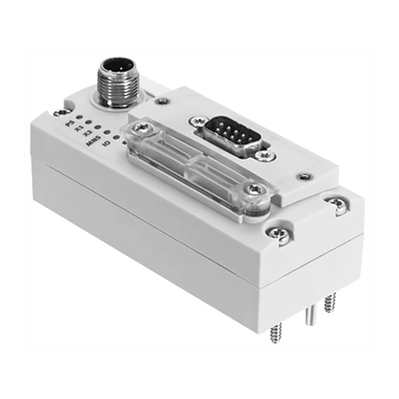
Universal bus node, Fieldbus protocol PROFIBUS-DP
Brand:
Festo
| Category:
Cables and connectors
| Size: 2 MB
Table of Contents
Table of Contents
5
Intended Use
9
Range of Application and Certifications
9
Instructions on this Description
10
Service
10
Target Group
10
Important User Instructions
11
1 Installation
15
Installation
16
General Instructions on Installation
17
Installation
17
Mounting
19
Connection and Display Components
20
Power Supply
21
Setting the DIL Switches
23
Removal and Mounting of the DIL Switch Cover
23
Setting the DIL Switches
24
Connecting the Fieldbus
27
Fieldbus Cable
27
Cable Specifications
27
Fieldbus Baud Rate and Fieldbus Length
28
Fieldbus Interface at the Bus Node
29
Connection Technology for Fieldbus Interface
30
Bus Terminal
34
Functional Test
35
2 Commissioning
37
Commissioning
38
General Remarks on the Fieldbus Protocol PROFIBUS-DP
40
Components
40
Commissioning
40
Data Exchange with the PROFIBUS-DP Fieldbus Protocol
41
Brief Overview of the Function Range
41
Control Commands
41
Modules/Devices at I-Port Connection 1 and
43
Installation on a Higher-Level Controller
46
Device Master File (GSD) and Symbol Files
46
Configuration by Using Process Data
48
Configuration Examples
48
Configuration of a DP Master
52
Bus Start-Up
52
Configuration Using a DP Master from Siemens as an Example
53
Identification and Maintenance
62
Overview of the I&M Data Structures
62
Load Identification Properties into the Bus Node Using Step
63
Check Identification Properties Using Step 7
64
Parameterisation (DP)
67
Parameterisationwhen Being Switched on (Start Behaviour)
68
Equipment Parameters
68
Parameterisation of the Bus Node
69
Bus Node Parameters Tool Change
70
Application Example for the Parameterisation
73
Communication
74
Statuses When Communication Is Established
74
Fail State Behaviour
76
Diagnostics
81
Diagnostics
82
Diagnostics
83
Diagnostics Via LED Display
84
Normal Operating Status Display
84
PS-LED Status Display
85
Status Display X1-/X2-Leds
86
Status Display BF-LED
88
Diagnostics Via Fieldbus
89
Diagnostic Steps
89
Details of the Channel-Related Diagnostics
94
Channel-Related and Extended Diagnostic Data
97
Event Codes of Connected Equipment
97
Diagnostics Via Controller or DP Master
98
Diagnostics for DP Masters, General
98
Diagnostics with Siemens SIMATIC S7
98
Online Diagnostics with STEP 7
100
Read out Diagnostic Buffer with STEP 7 (up to V 5.5)
100
Device-Specific Diagnostics with STEP 7 (up to V 5.5)
102
Error Handling
105
Summary of Diagnostics Options
83
Error Handling
106
Error Handling
107
Restart Communication between the Bus Node and the Device
108
Check Fieldbus Communication
109
Check PROFIBUS-DP Configuration
109
Read out Diagnostic Messages Via Controller
110
Fault Finding and Error Elimination
107
Check Installation
107
Check the Power Supply
107
Technical Appendix
112
Technical Appendix
113
Technical Data
113
Access to the Bus Node Via DPV1
117
Reading and Writing Data Records
117
Data Records for DP-Master Controls, General
120
Operation with the General DP Master
124
Sending Parameterisation Data
124
Checking the Configuration Data
126
Reading Diagnostic Information
128
Implemented Functions and Service Access Points (SAP
128
Transmission Times at the Master
129
Advertisement
Advertisement
Related Products
Festo CTEU-EC
Festo CTEU-CO
Festo CTEU-DN
Festo CPX-4AE-P Series
Festo CPA14-IFB-CP
Festo CLR-40-10-L-P-A-K11-R8
Festo CMMT-ST-C8-1C-EC-EP
Festo CPV10-GE-ASI-8E6A-Z-M8
Festo CLR-32-10-L-P-A
Festo CDVI-DN Series
Festo Categories
Industrial Equipment
Control Unit
Controller
Touch terminals
DC Drives
More Festo Manuals
Login
Sign In
OR
Sign in with Facebook
Sign in with Google
Upload manual
Upload from disk
Upload from URL