Advertisement
Quick Links
Bus node
CTEU-AS
Description
Installation and interfaces
Original: de
Bus node CTEU-AS
. . . . . . . . . . . . . . . . . . . . . . . . . . . . . . . . . . . . . . . . . . . . .
1
Instructions on this description
This description includes information for mounting the bus node on an I-port-com-
patible device from Festo (e.g. valve terminal with I-port interface) and for installa-
tion of this combination in a higher-level control system.
®
®
AS-Interface
and TORX
trademark owners in certain countries.
2
Intended use
The bus node type CTEU-AS has been designed exclusively for use as a slave on
the AS-interface fieldbus. It may only be used in its original status without unau-
thorised modifications and only in perfect technical condition.
The bus node is intended for use in an industrial environment. Outside of industrial
environments, e.g. in commercial and mixed-residential areas, actions to suppress
interference may have to be taken.
3
Target group
The target group for this description consists of trained specialists in control and
automation technology who have experience with installation of stations on the
AS-interface fieldbus.
4
Mounting
Warning
Danger of injury to people, damage to the machine and system resulting from
uncontrolled movements of the actuators and undefined switching states
• Switch off the operating and load voltage supplies.
• Switch off compressed air supply.
• Exhaust the pneumatics valve terminal.
Note
Damage to the electronics
The bus node includes electrostatically sensitive devices.
• Do not touch any electrical/electronic components.
• Observe the handling specifications for electrostatically sensitive devices.
Note
Use cover caps to seal unused connections. You will then achieve degree of pro-
tection IP65/IP67.
Festo AG & Co. KG
Postfach
73726 Esslingen
Germany
+49 711 347-0
www.festo.com
8032384
1405NH
[8032386]
are registered trademarks of the respective
Information on mounting the bus node on the decentralised electrical
connecting plate CAPC-... can be found in the mounting instructions that
accompany the connecting plate.
The bus node CTEU-AS supports only the X1 connection of the electrical
connecting plate CAPC-.... The X2 connection on the electrical connecting
plate CAPC-... is without a function for the CTEU-AS bus node.
For mounting the bus node on a valve terminal with I-Port interface, proceed as
follows:
1. Inspect the seals and sealing surfaces on bus node and valve terminal.
2. Plug the bus node onto the valve terminal in the right position and without tilt-
ing.
3. Screw the three self-tapping screws in by hand. You can use the threads already
present when you screw it in again.
4. Tighten the screws by hand in diagonally opposite sequence, with a tightening
torque of 0.7 ± 0.1 Nm.
5
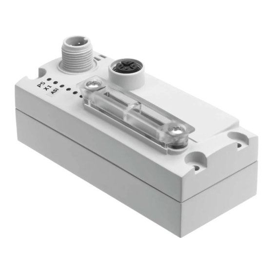
Connection and display components
The following electrical connection and display components can be found on the
bus node:
English
4
1
DIL switch group (
2
Status LEDs (status display/
diagnostics
3
M12 plug for AS-interface bus and
additional power supply (AS-i In)
(
chap. 6)
Fig. 1
6
Connect AS-interface bus and auxiliary power supply
The bus node also supplies voltage to equipment connected via the I-port inter-
face.
Warning
Danger of electric shock
• Only use PELV circuits in accordance with IEC/EN 60204-1 (protective extra-
low voltage, PELV) for the electrical power supply.
• Observe also the general requirements for PELV power circuits in accordance
with IEC/EN 60204-1.
• Only use voltage sources which guarantee reliable electrical isolation of the
operating voltage in accordance with IEC/EN 60204-1.
Through the use of PELV circuits, protection against electric shock (protection
against direct and indirect contact) is ensured in accordance with IEC/EN 60204-1.
Observe with branch lines:
– the maximum overall length of the AS-interface bus (100 m without repeater/
extender)
– the line length of the load voltage connection cable (depends on the current
consumption of the valve terminal and fluctuations in load voltage).
M12 plug, AS-interface In
4
3
1
2
Fig. 2
1
2
3
4
chap. 7.2)
M12 socket, AS-interface bus and
additional power supply (AS-i Out)
chap. 8)
(
chap. 6 )
Pin
Allocation
1
AS-interface +
2
0 V (auxiliary power supply)
3
AS-interface –
4
24 V (auxiliary power supply)
Advertisement

Related Manuals for Festo CTEU-AS


Summary of Contents for Festo CTEU-AS
- Page 1 (AS-i In) Intended use chap. 6) The bus node type CTEU-AS has been designed exclusively for use as a slave on Fig. 1 the AS-interface fieldbus. It may only be used in its original status without unau- thorised modifications and only in perfect technical condition.
- Page 2 M12 socket, AS-interface Out Allocation Assignment of slave addresses to physical outputs/valves of the connec- ted devices can be found in the respective product documentation. AS-interface + 0 V (auxiliary power supply) Status display/diagnostics AS-interface – 8.1 Status display via LEDs 24 V (auxiliary power supply) PS (power system) –...
- Page 3 Through use of PELV circuits (Protection against direct and indirect contact in accordance with IEC/DIN 60204-1) Electromagnetic compatibility (EMC) See declaration of conformity – emitted interference www.festo.com – resistance to interference Vibration and shock Severity level (SL) for mounting on (as per EN 60068) –...
Need help?
Do you have a question about the CTEU-AS and is the answer not in the manual?
Questions and answers