Table of Contents
Advertisement
Quick Links
Download this manual
See also:
Manual
Advertisement
Table of Contents
Troubleshooting

Related Manuals for Symmetricom TimeSource 3600


Summary of Contents for Symmetricom TimeSource 3600
- Page 1 TimeSource 3600 GPS Primary Reference Source User’s Guide Revision J – June 2007 Part Number 097-72060-01...
- Page 2 2300 Orchard Parkway San Jose, CA 95131-1017 U.S.A. http://www.symmetricom.com Copyright © 2007 Symmetricom, Inc. All rights reserved. Printed in U.S.A. All product names, service marks, trademarks, and registered trademarks used in this document are the property of their respective owners.
- Page 3 Chapter 1 Overview of the TimeSource 3600 Overview ............22 Global Positioning System .
- Page 4 Shelf Considerations ..........49 TimeSource 3600 User’s Guide...
- Page 5 Chapter 3 Installing the TimeSource 3600 Unpacking ........... . .58 Installing the Antenna .
- Page 6 Alarms Output ..........93 Powering Up the TimeSource 3600 ....... . .94 Installing and Using TimeWizard.
- Page 7 User Guide Updates ..........195 097-72060-01 Revision J – June, 2007 TimeSource 3600 User’s Guide...
- Page 8 Shelf ............214 TimeSource 3600 User’s Guide...
- Page 9 Two ESCIU Outputs Option ......... 33 TimeSource 3600 Passthrough Function ....... 34 Antenna Field of View.
- Page 10 Cisco Systems Data Format........203 TimeSource 3600 User’s Guide...
- Page 11 Message Troubleshooting ........187 097-72060-01 Revision J – June, 2007 TimeSource 3600 User’s Guide...
- Page 12 List of Tables TimeSource 3600 User’s Guide 097-72060-01 Revision J – June, 2007...
- Page 13 Replacing Cards ..........192 097-72060-01 Revision J – June, 2007 TimeSource 3600 User’s Guide...
- Page 14 List of Procedures TimeSource 3600 User’s Guide 097-72060-01 Revision J – June, 2007...
-
Page 15: How To Use This Guide
Structure of This Guide Conventions Used in This Guide Warnings, Cautions, Recommendations, and Notes Related Documents and Information Where to Find Answers to Product and Document Questions What’s New In This Guide 097-72060-01 Revision J – June, 2007 TimeSource 3600 User’s Guide... -
Page 16: Purpose Of This Guide
Symmetricom TimeSource 3600 GPS Primary Reference Source. It also describes the alarms and events, the languages that you use to communicate with the TimeSource 3600, default values, and other information. Who Should Read This Guide... -
Page 17: Conventions Used In This Guide
An explanation of the key’s acronym or function immediately follows the first reference to the key, if required. Text in a source file or a system prompt or other text that TS3600 appears on a screen. Username: 097-72060-01 Revision J – June, 2007 TimeSource 3600 User’s Guide... -
Page 18: Warnings, Cautions, Recommendations, And Notes
Electrical shock cautions are practices, procedures, or statements, that if not strictly observed, may result in possible personal injury, electrical shock damage to, or destruction of components of the equipment. TimeSource 3600 User’s Guide 097-72060-01 Revision J – June, 2007... -
Page 19: Related Documents And Information
Where to Find Answers to Product and Document Questions For additional information about the products described in this guide, please contact your Symmetricom representative or your local sales office. You can also contact us on the web at www.symmetricom.com. What’s New In This Guide... - Page 20 How to Use This Guide What’s New In This Guide TimeSource 3600 User’s Guide 097-72060-01 Revision J – June, 2007...
-
Page 21: Chapter 1 Overview Of The Timesource
Chapter 1 Overview of the TimeSource 3600 This chapter provides an overview of the global positioning system and a physical and functional description of the TimeSource 3600. In This Chapter Overview Global Positioning System Physical Description Functional Description 097-72060-01 Revision J – June, 2007... -
Page 22: Overview
12, are in view anywhere in the world at all times. The TimeSource 3600 tracks all satellites within its field of view. The performance of each tracked satellite is observed and compared to the others, and available for use in the timing solution. -
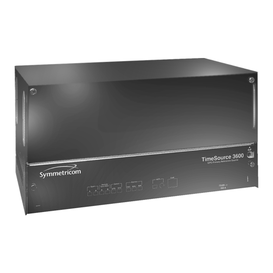
Page 23: Physical Description
1-1) can be mounted in a 48 cm rack or an ETSI 53.5 cm rack. One RU (4.45 cm) of air space above the TimeSource 3600 is required for proper ventilation. Other than a communications connector on the front panel, all connectors are at the connector panel. -
Page 24: Shelf
Chapter 1 Overview of the TimeSource 3600 Physical Description 22 cm 8.2 cm 43.8 cm 990-72060-01, -02, -05, -06 Systems 22 cm 8.2 cm 43.8 cm 990-72060-04 Systems Figure 1-1. Shelf TimeSource 3600 User’s Guide 097-72060-01 Revision J – June, 2007... -
Page 25: Roof Antenna
Chapter 1 Overview of the TimeSource 3600 Physical Description Roof Antenna The roof antenna (Figure 1-2) is encased in weather-resistant plastic housing for outdoor installation, usually on a roof. A single coaxial cable carries signals and power between the antenna and the shelf. -
Page 26: Self-Adhesive Window Antenna
Chapter 1 Overview of the TimeSource 3600 Physical Description Antenna Coaxial Cable Mounting Assembly IF Converter 43 cm Coaxial Cable to TimeSource 3600 Shelf (not included with antenna assembly) Figure 1-3. Mechanical Window Antenna Self-Adhesive Window Antenna The self-adhesive window antenna assembly... -
Page 27: Wall Antenna
Wall Antenna Functional Description Figure 1-6 shows the main functions of the TimeSource 3600. The center of the TimeSource 3600 is the BesTime Ensemble Timing Generator, which uses the BesTime algorithm to analyze the phase and frequency relationships, individually and collectively, of the timing sources. Each type of timing source has a particular... -
Page 28: Antenna
Chapter 1 Overview of the TimeSource 3600 Functional Description Figure 1-6. Block Diagram Table 1-1. Timing Source Characteristics Source Characteristic Local Oscillator Short term stability E1 Line Intermediate term stability GPS Signal Long term stability Antenna The antenna types include a roof antenna, mechanical window antenna, self-adhesive window antenna, or wall antenna. -
Page 29: Zone Of Protection
Antenna Installation and Lightning Protection The TimeSource 3600 standard wall antenna kits do not include lightning protectors. When the antenna is installed on the side of the building, the antenna is in the zone of protection and is protected from lightning strikes as described in the Standard for the Installation of Lightning Protection Systems (NFPA 780), 2000 edition. -
Page 30: If Interface
If the wall antenna is installed outside the zone of protection, Symmetricom offers an outdoor and/or indoor lightning protector kits for these installations. Refer to Chapter 2, Engineering &... -
Page 31: Ntp Timeserver
Use of the Network Time Protocol (NTP) feature requires activation with a password. Activation is accomplished through receipt of a Network Time Protocol Activation Certificate from Symmetricom. This certificate contains the unit purchase order number, unit model number, unit activation date, unit serial number, and unit activation key. -
Page 32: Eight Mixed E1/T1 Outputs
Chapter 1 Overview of the TimeSource 3600 Functional Description Eight Mixed E1/T1 Outputs This feature enables a user to mix any combination of E1 and T1 outputs. A user can also use any combination of framing. For E1, CCS, CAS, CCS with CRC4, and CAS with CRC4 can be used per G.703 table 6. -
Page 33: Two Esciu Outputs (990-72060-04 Systems Only)
TimeSource 3600 and an external terminal. Ethernet TimeSource 3600 has six Ethernet ports to carry TL1 commands, responses, and autonomous messages between the TimeSource 3600 and an external terminal, or an Element Manager, or both. The user can configure the IP address, subnet mask, and gateway address for the Ethernet ports. -
Page 34: Passthrough
The TID (SID for DCD) is used to identify commands that go to the DCD product. The TimeSource 3600 passes any TID not its own through to the DCD product. In the reverse direction, all commands received from the DCD product are passed through to the user Note: The TID of the TL1 command must be the SID of MIS. -
Page 35: Alarm Programmability
Chapter 1 Overview of the TimeSource 3600 Functional Description Alarm Programmability Releases of TimeSource (1.05.03 and above) allow the user to provision the alarm escalation parameters that were hardcoded in the previous releases of TS3000.hex. The defaults for this release remain the same as were previously hardcoded. This feature can be used to set the programmability for such alarms as GPS, HOLDOVER, SPAN-X, and RO-X. -
Page 36: Bridging/Holdover Behavior
This ensures that intermittent conditions are not flagged unnecessarily. During the normal working of the TimeSource 3600, it is a very common occurrence that the GPS satellites may not be visible during certain parts of the day, depending on the installation of the antenna. -
Page 37: Time Figure Of Merit
Chapter 1 Overview of the TimeSource 3600 Functional Description The system allows the user to set various parameters for GPS error, Holdover error, and SPAN error conditions. These parameters are: Initial Severity Initial Service Affecting state Integration Time Final Severity... - Page 38 Chapter 1 Overview of the TimeSource 3600 Functional Description Installations with full view to the sky see 4 satellites 23+ hours a day, seven days a week. It is relatively easy to filter out multipath signals using multiple satellites and simple voting schemes.
-
Page 39: Success Rate
Chapter 1 Overview of the TimeSource 3600 Functional Description Success Rate Success rate is a moving 24-hour window indicating the TimeSource's ability to lock to and use the GPS as part of the system's timing solution. This metric is reported as a percentage (%) ratio of the total good minutes that the system uses GPS in a day (maximum 1440 minutes/day). - Page 40 Chapter 1 Overview of the TimeSource 3600 Functional Description TimeSource 3600 User’s Guide 097-72060-01 Revision J – June, 2007...
- Page 41 This chapter provides information to assist in planning the installation and ordering a system appropriate for a specific site. In This Chapter Antenna Guidelines Shelf Considerations Systems Antennas User-Supplied Tools and Materials 097-72060-01 Revision J – June, 2007 TimeSource 3600 User’s Guide...
-
Page 42: Antenna Guidelines
Determine the two separate –48 V power sources for the shelf. If only one –48 V power source is available, it must be cabled to both TimeSource 3600 power inputs. -
Page 43: Roof Antenna Location And Cabling Guidelines
A compromise often must be made between location and satellite field of view. With a smaller field of view, the TimeSource 3600 can use fewer satellites in the solution for GPS derived time. The TimeSource 3600 will operate with an average of one satellite in view for 40 percent of the time in a day. -
Page 44: Antenna Location Examples
A transmitting antenna may cause the GPS antenna to become overloaded and reduce its reception capabilities. The minimum horizontal distance from other receiving antennas is 1 meter. TimeSource 3600 User’s Guide 097-72060-01 Revision J – June, 2007... - Page 45 Any opening where conduit enters the building must be waterproofed per local company practices. Treat all exposed connections with an electrically conductive anti-corrosion compound (Kopr-Shield or equivalent). Caution: To prevent damage to cables, avoid small-radius turns and unnecessary turns. 097-72060-01 Revision J – June, 2007 TimeSource 3600 User’s Guide...
-
Page 46: Roof Antenna Earth Ground Location Guidelines
305 m cable (060-72010-99) Two cables are required: one to connect the antenna to the lightning suppressor, and another to connect the lightning suppressor to the TimeSource 3600 Shelf. Optionally, one length of coaxial cable may be ordered, which must be cut and prepared with end-connectors at the point where the suppressor is located. -
Page 47: Window And Wall Antenna Location Guidelines
*An angle of 10° masks objects up to about 1 m above the horizon at 6 m from the antenna. Figure 2-4. Antenna Mask Angle 097-72060-01 Revision J – June, 2007 TimeSource 3600 User’s Guide... -
Page 48: Window And Wall Antenna Cable Choices
152 m cable (060-72050-50) IRIG-B TOD (990-72060-05 System Only) If you are using the IRIG-B TOD outputs (990-72060-05 TimeSource 3600 System), right-angle BNC connectors are provided to prevent small radius turns in the IRIG-B TOD cables. The right-angle BNC connectors may be attached to the IRIG-B BNC connectors, to direct the cables from the shelf as desired. -
Page 49: Rs-422–To–Rs-232 Tod Converter
Shelf Considerations The TimeSource 3600 Shelf can be mounted in an ETSI 53.5 cm rack or a 48 cm rack. The shelf is shipped with supplied mounting ears positioned for flush mounting on an ETSI 53.5 cm rack. Attach the mounting ears, as shown in Figure 2-5., for flush mounting or 12.7 cm offset mounting. -
Page 50: Systems
B. Flush mounting – 48 cm rack C. 12.7 cm offset – 48 cm rack Figure 2-5. Rack Mounting Options Systems The TimeSource 3600 Systems available are listed below. The antenna must be ordered separately. Standard System (Two E1 Outputs) This system (990-72060-01) includes:... -
Page 51: With Two E1 Synchronization Insertion (Esciu) Ports
Chapter 2 Engineering & Ordering Systems TimeSource 3600 card with additional E1 or 2.048 MHz outputs (090-72060-02) Hardware kit (093-72060-87) System software CD (992-72060-xx) Version 1.05.04 or higher TimeScan Craft (keyless version) software CD (992-46750-xx) Version 7.2.0 or higher With Two E1 Synchronization Insertion (ESCIU) Ports... -
Page 52: Timesource 3600 User's Guide 097-72060-01 Revision J – June
Version 1.05.04 or higher TimeScan Craft (keyless version) software CD (992-46750-xx) Version 7.2.0 or higher Antennas The antennas available are listed below. A TimeSource 3600 System must be ordered separately. Roof Antenna Antenna and mounting hardware kit (990-72050-96) includes: IF antenna assembly (090-72010-71) Mounting hardware kit (093-72010-71) (x1) which includes: –... -
Page 53: Self-Adhesive Window Antenna
Wall antenna indoor lightning suppressor kit (093-72050-94) (optional) includes: – Mounting bracket (070-00300-02) – Surge protector (143-00018-01) – RG59 cable, 0.78 m (060-72010-92) Wall antenna L1 outdoor lightning suppressor kit (093-72050-93) (optional) includes: 097-72060-01 Revision J – June, 2007 TimeSource 3600 User’s Guide... -
Page 54: User-Supplied Tools And Materials
Electrically conductive antioxidant compound (Kopr-Shield or equivalent) to coat exposed connections to prevent oxidation. Tool to cut cable, if installation requires custom lengths of cable. Phillips Screwdriver Wrench 1/4 inch hex Allen wrench TimeSource 3600 User’s Guide 097-72060-01 Revision J – June, 2007... -
Page 55: For Mechanical Window Antenna Installation
GPS handheld receiver, personal computer with GPS location software, or other method of determining latitude, longitude, and altitude For Shelf Installation A Phillips-head screwdriver for installing the TimeSource 3600 Shelf in a rack Four screws to mount the shelf in a rack 097-72060-01 Revision J – June, 2007... -
Page 56: Outputs, Power, And Miscellaneous
RS-232 cable with DB-9 connector for COM2 port 4.115 mm (6 AWG) ground wire 1.47 mm (16 AWG) green insulated ground wire 1.47 mm (16 AWG) red insulated wire 1.47 mm (16 AWG) black insulated wire TimeSource 3600 User’s Guide 097-72060-01 Revision J – June, 2007... -
Page 57: Chapter 3 Installing The Timesource
Chapter 3 Installing the TimeSource 3600 This chapter is the sequential order of procedures for installation and power-up. In This Chapter Unpacking Installing the Antenna Installing the Shelf Powering Up the TimeSource 3600 Installing and Using TimeWizard Factory-Set Values 097-72060-01 Revision J – June, 2007... -
Page 58: Unpacking
Unpacking Use the procedures in the order they appear in this chapter to install the TimeSource 3600. If any difficulties are encountered during the installation process, contact Symmetricom’s Customer Technical Assistance Center (CTAC). Refer to the Technical Assistance section of the Troubleshooting chapter for telephone numbers. -
Page 59: Roof Antenna-To-Shelf Cabling
Chapter 3 Installing the TimeSource 3600 Installing the Antenna To install the antenna, refer to Figure 3-1 and perform Procedure 3-1. Ensure all user-supplied materials are available. Warning: To prevent arcing, ensure that the lightning suppressor is placed away from electrical devices and cabling. - Page 60 Chapter 3 Installing the TimeSource 3600 Installing the Antenna Procedure 3-1. Mounting a Roof Antenna and Connecting the Cable Step Procedure Attach the antenna mounting bracket to a pipe (2.5 cm diameter) or a wood post. If mounting the bracket to a pipe, slide the two V-bolts over the pipe, and through the mounting bracket slots;...
- Page 61 Chapter 3 Installing the TimeSource 3600 Installing the Antenna Procedure 3-1. Mounting a Roof Antenna and Connecting the Cable (Continued) Step Procedure Mount the antenna and mast assembly to the “L” bracket Connect the mast to the flange using PVC glue.
- Page 62 Connect a cable to the lightning suppressor, route the cable through the conduit into the building, and route the cable through the building to the TimeSource 3600 Shelf location. If the lightning suppressor was not mounted directly to a valid earth ground, crimp a length of 4.115 mm (6 AWG) ground cable to the two-hole terminal, slide the terminal over two of...
-
Page 63: Installing A Mechanical Window Antenna
Chapter 3 Installing the TimeSource 3600 Installing the Antenna installing a Mechanical Window Antenna Installation procedures are to follow local company procedures and the Installation Job Specification. Prior to installing the antenna, the site, antenna location, cable route, and all other details should have been planned. - Page 64 3-4). Connect the antenna cable to the IF downconverter on the mechanical window antenna assembly and route the cable to the TimeSource 3600 Shelf location. Secure the cable using local company procedures. Check all connections for tightness to prevent intermittent operation.
-
Page 65: Installing A Self-Adhesive Window Antenna
Chapter 3 Installing the TimeSource 3600 Installing the Antenna Use 2 user-supplied screws to attach to wall or window sill Figure 3-3. Attaching the Mechanical Window Antenna Place the antenna against the window by moving the chassis on these pivots. -
Page 66: Self-Adhesive Window Antenna-To-Shelf Cabling
Chapter 3 Installing the TimeSource 3600 Installing the Antenna Antenna 090-71010-87 Antenna-to-IF cable (3 m) 060-00062-01 Antenna kit 990-72050-98 SMA connector (Attached to cable, and on IF converter) IF converter 090-72050-72 and Mounting Kit IF-to-shelf cable RG-59/U Cable TNC connector... -
Page 67: Attaching The Self-Adhesive Window Antenna To A Window
3 m. Route and connect the antenna cable to the antenna side of the IF downconverter. Connect a cable to the TimeSource 3600 shelf side of the IF downconverter and route the cable to the shelf location. -
Page 68: Installing A Wall Antenna
Chapter 3 Installing the TimeSource 3600 Installing the Antenna Installing a Wall Antenna Prior to installing the antenna, the site, antenna location, cable route, and all other details should have been planned. Installation procedures are to follow local company procedures and the Installation Job Specification. - Page 69 Chapter 3 Installing the TimeSource 3600 Installing the Antenna Procedure 3-4. Installing a Wall Antenna Step Procedure Prerequisite: Observe all guidelines, considerations, Dangers, Warnings, Cautions, and Notes in the Engineering and Ordering chapter. Symmetricom Parts: Wall Antenna (990-72050-95 with 1.8 m antenna cable or 990-72050-99 with 5.8 m antenna...
- Page 70 Procedure 3-4. Installing a Wall Antenna (Continued) Step Procedure Connect a cable to the TimeSource 3600 shelf side of the IF converter and route the cable to the shelf location. Secure the cable using local company procedures. Install fire-stopping material in all holes opened in the roof and/or walls during this procedure.
- Page 71 Route the 3 m RG-316 cable provided from the outdoor lightning suppressor through the wall to the IF converter and connect both ends. Connect the user provided RG-59 cable from the IF converter to the TimeSource 3600 shelf. Install fire-stopping material in all holes opened in the roof and/or walls during this procedure.
-
Page 72: Hole Spacing
Chapter 3 Installing the TimeSource 3600 Installing the Antenna 5 cm Bracket mounting hole (2) 8.6 cm Antenna Cable hole Figure 3-9. Hole Spacing Holes for bolts/screws Mounting bracket Antenna cable Hole for cable Antenna Wall Drip loop Building interior Building exteri Figure 3-10. -
Page 73: Installing The Shelf
(Figure 3-12C). Leave 1 RU (4.45 cm) of air space above the TimeSource 3600 Shelf for proper ventilation. Mount the shelf in the rack according to standard company practices. Note: Two screws may be used in both mounting ears if the holes in the rack are spaced 4.45 cm apart. -
Page 74: Installing Output Modules
Chapter 3 Installing the TimeSource 3600 Installing the Shelf Rack rails Rear of rack Top of shelf Mounting ears A. ETSI – 53.5 cm rack Rack rails Mounting ears Rear of rack Rear of rack Top of shelf Top of shelf... -
Page 75: Making Power And Signal Connections
Chapter 3 Installing the TimeSource 3600 Installing the Shelf OPTIONS I/O connector Threaded screw holes Figure 3-13. Options I/O Connector Making Power and Signal Connections ESD Caution: To avoid electrostatic discharge (ESD) damage, wear an ESD wrist strap when making connections to the connector panel. -
Page 76: Making Frame Ground Connections
Chapter 3 Installing the TimeSource 3600 Installing the Shelf E1 outputs Battery A port 1 Alarms E1 inputs A & A & B & frame (BNC) 10 MHz 1 pps ground Time of day output port 2 output (TB1) E1 outputs... -
Page 77: Connector Panel Terminal Block Connections
Chapter 3 Installing the TimeSource 3600 Installing the Shelf TB (1 or 2) BATT (A or B) Figure 3-15. Connector Panel Terminal Block Connections Ensure the frame ground wires are long enough to reach from the shelf connector panel to the frame ground connection. Use one 1.47 mm (16 AWG) green insulated... -
Page 78: Making Power Connections
Caution: To avoid damage to the system, do not apply power to the TimeSource 3600 before instructed in this procedure. Before connecting the power cables to the TimeSource 3600, ensure the fuses are removed from the fuse panel that supplies power to the power cables. -
Page 79: Mhz Output
Chapter 3 Installing the TimeSource 3600 Installing the Shelf 10 MHz Output Connect a user-supplied RG-58 coaxial cable from the connector labeled 10 MHz to the equipment that will use the 10 MHz output signal. See Figure 3-14 for the connector location. -
Page 80: Connecting E1 Or Analog Reference Inputs
TimeSource 3600. In either case, connect reference inputs to the wire-wrap pins or BNC connectors labeled SPAN IN A and SPAN IN B. If using the wire-wrap pins, connect the tip wire to the pin labeled T, the ring wire to the pin labeled R, and the shield (if connected at the TimeSource 3600) to the pin labeled S. -
Page 81: Eight E1 Or Analog Input Connections
Note: The shield pin is capacitively coupled to ground, therefore, the shield must be connected at the source end. The shield may also be connected at the TimeSource 3600 end for additional longitudinal noise protection. Wire-Wrap OUT 8... -
Page 82: Irig-B Tod Output Connections
Chapter 3 Installing the TimeSource 3600 Installing the Shelf Module for IRIG-B TOD Outputs (990-72060-05 System Only) Connect up to four optional IRIG-B TOD outputs at the output module. See Figure 3-14 for the connector location, and Figure 3-19 for the connections. -
Page 83: Module For Mixed E1/T1 Outputs (990-72060-06 System Only)
E1 traffic signal. A bypass relay directs E1 traffic around the ESCIU circuitry to maintain span continuity if a TimeSource 3600 fault occurs. 097-72060-01 Revision J – June, 2007 TimeSource 3600 User’s Guide... -
Page 84: Cutover Procedures For Out-Of-Service Equipment
5. Verify that there are no alarms on the NEs on the E1 system. If there are alarms, recheck the new cabling between the NEs and the ESCIU module. Note: If the TimeSource 3600 is still in warm-up or searching for GPS satellites, alarms may be present. All synchronization-related alarms should clear while the TimeSource 3600 is in steady-state operation. -
Page 85: Cutover Procedures For In-Service Equipment
Chapter 3 Installing the TimeSource 3600 Installing the Shelf 6. Restore (turn up) the traffic trunks to service. REMOVE EXISTING CABLING NETWORK RECEIVE RECEIVE ELEMENT OR NETWORK (IN) (IN) FACILITY ELEMENT NOT BEING BEING TIMED TIMED FROM FROM ESCIU ESCIU... - Page 86 Step 1 and recheck the cross-connect wiring. Repeat Step Note: If the TimeSource 3600 is still in warm-up or searching for GPS satellites, alarms may be present. All synchronization-related alarms should clear while the TimeSource 3600 is in steady-state operation.
-
Page 87: Esciu Cutover With Jacks (In-Service)
Chapter 3 Installing the TimeSource 3600 Installing the Shelf PRIMARY REFERENCE DIGITAL LINE INTERFACE INTF PORT EQPMT DIGITAL SWITCH MACHINE* SECONDARY REFERENCE DIGITAL LINE INTERFACE INTF PORT EQPMT RTN1 OUT RTN1 IN Patch Cord Bridging Repeaters DSX-1 Jacks Existing cabling... -
Page 88: Time Of Day Output
Chapter 3 Installing the TimeSource 3600 Installing the Shelf Time of Day Output Connect a time of day (TOD) output at the female RJ-45 connector labeled TOD. Figure 3-14 for the connector location, and Table 3-1 for the connector pinouts. -
Page 89: Rs-422–To–Rs-232 Tod Converter Mounting Plate
Notes: 1. Due to distance constraints, the converter must be placed no more than 305 m from the TimeSource 3600 Shelf, and no more than 15 m from the device receiving the time code. 2. The converter dimensions are 7.5 cm by 3.8 cm by 2.5 cm. -
Page 90: Ethernet
Chapter 3 Installing the TimeSource 3600 Installing the Shelf Table 3-2. Converter DB-25 Connector Pinouts Signal Frame ground Data output (RS-232) 1 pps (RS-232) Signal ground Note: Pins not listed are reserved for future use. Ethernet Connect a user-supplied Ethernet cable from the network to the 10base-T Ethernet connector labeled E-NET. -
Page 91: Communication Port 1
Chapter 3 Installing the TimeSource 3600 Installing the Shelf Communication Port 1 To provide an RS-232 link for TL1 command access to the TimeSource 3600, connect to port 1 at the female 25-pin D connector labeled COM1. See Figure 3-14 for the location of the connector. -
Page 92: Craft Port
Note: Pins not listed are reserved for future use. Craft Port To provide an RS-232 link for TL1 command access to the TimeSource 3600, connect to the craft port at the female RJ-45 connector labeled Craft on the front panel. A Craft-port-to-PC cable is supplied with the TimeSource 3600 for making this connection. -
Page 93: Alarms Output
From TimeSource 3600 Note: Pins not listed are reserved for future use. Alarms Output Connect the TimeSource 3600 alarms to the office alarm panel at the critical (CR), major (MJ), and minor (MN) wire-wrap pins. See Figure 3-14 for the location of the... -
Page 94: Powering Up The Timesource 3600
8 data bits, no parity bit, 1 stop bit, and 9600 baud. On the computer connected to the TimeSource 3600, connect the computer communication port to the COM1, COM2, or Craft port on the TimeSource 3600. A craft port-to-PC communication cable is provided in the hardware kit for this purpose. - Page 95 Install the battery source fuse(s) in the rack fuse bay that supplies power to the TimeSource 3600. The TimeSource 3600 enters its warm-up mode after approximately 60 s when power is applied. During the warm-up period, the following conditions exist:...
- Page 96 MANLONG=W-121-59-246,MANELEVALT=12; Notes: 1. The TimeSource 3600 can find its position on the earth without latitude, longitude, and altitude entered, but the process may take several hours, and may not result in the position accuracy (within 200 m) required for the system to perform to specification. It is recommended that the information be obtained and manually entered by the user.
- Page 97 Chapter 3 Installing the TimeSource 3600 Powering Up the TimeSource 3600 Procedure 3-6. Power-Up (Continued) Step Procedure If UTC time is desired, skip to Step 18. Use the Edit Date command to set the local date and time. ED-DAT:::<ctag>::yyyy-mm-dd,hh-mm-ss:MODE=LOCAL; yyyy – year (yyyy = 1998 to 2096) mm –...
- Page 98 COM1, COM2, or the CRAFT port to set the IP address, subnetwork mask, and gateway address for the current TimeSource 3600 unit, as required for proper operation in the managed element network. (These parameters affect all Ethernet ports. The Ethernet port should be closed and all users logged off before issuing this command.)
- Page 99 Procedure 3-6. Power-Up (Continued) Step Procedure Ports 5001, 5002, 5003 and 5004 on the TimeSource 3600 are used as though they were serial TL1 communication ports. The following values are set at the factory and appear at reset: MONMSG – INH (monitors only the current port for messages) KEEPALIVE = 0 –...
- Page 100 27. Use the Edit Equipment command to set the IP address and port address of the Element Manager. Port 5550 connects to this address when the TimeSource 3600 develops a TL1 autonomous message, sends any messages, and closes the connection. An alternate Element Manager may be set up in case port 5550 cannot make a connection to the primary Element Manager.
- Page 101 Chapter 3 Installing the TimeSource 3600 Powering Up the TimeSource 3600 Procedure 3-6. Power-Up (Continued) Step Procedure Use the Edit Communications command to set the communications parameters of port 5551. An Element Manager connects to port 5551 for TL1 command and response messages.
- Page 102 This may be useful when testing, troubleshooting, or in installations where a TimeSource 3600 that is in major alarm may produce better timing signals than other sources (for example, offices without additional holdover clocks in a distribution shelf).
- Page 103 If normal operation is not reached, refer to the Troubleshooting chapter. 4. The TimeSource 3600 develops and sends timing within the PRS specification during normal operation and during any event (other than settling period) or minor alarm, but not during a major or critical alarm.
-
Page 104: Installing And Using Timewizard
Procedure 3-7. TimeWizard Installation and Operation Step Procedure Use this procedure to install the firmware in the TimeSource 3600 to configure the GPS and Holdover alarms, using the TimeWizard application. Requirements: 1. A PC running Windows 95/98/NT 4.0/2000/XP. 2. The TimeSource 3600 System CD provided. - Page 105 Chapter 3 Installing the TimeSource 3600 Installing and Using TimeWizard Procedure 3-7. TimeWizard Installation and Operation (Continued) Step Procedure From the Windows desktop, click Start, Programs, TimeWizard to start the TimeWizard application. When TimeWizard starts, the “TimeWizard” main screen appears: The version of TimeWizard that is installed is indicated at the top right of the screen.
- Page 106 Chapter 3 Installing the TimeSource 3600 Installing and Using TimeWizard Procedure 3-7. TimeWizard Installation and Operation (Continued) Step Procedure After you click Next>> in Step 7, the “Download GPS.hex” screen appears: The versions of the GPS.hex and TS3000.hex firmware that are currently installed in the TimeSource are shown in the GPS.hex Ver and TS3000.hex Ver fields.
- Page 107 Download Progress dialog box. 2. If the download fails for any reason, a screen appears with instructions to contact Symmetricom. If this happens, exit the application, check the cable connections, and restart TimeWizard. After the Download Progress dialog box closes, continue to monitor the messages reported in the Commands area of the screen.
- Page 108 Download Progress dialog box. 2. If the download fails for any reason, a screen appears with instructions to contact Symmetricom. If this happens, exit the application, check the cable connections, and restart TimeWizard. After the Download Progress dialog box closes, continue to monitor the messages reported in the Commands area of the screen.
- Page 109 Chapter 3 Installing the TimeSource 3600 Installing and Using TimeWizard Procedure 3-7. TimeWizard Installation and Operation (Continued) Step Procedure Verify the Firmware Versions The “Status Information” screen appears as follows: Verify that GPS.hex Ver and TS3000.hex Ver fields show that the correct versions of the GPS.hex and TS3000.hex firmware are now installed, then click Next>>.
- Page 110 Chapter 3 Installing the TimeSource 3600 Installing and Using TimeWizard Procedure 3-7. TimeWizard Installation and Operation (Continued) Step Procedure Setup the Alarm Parameters The “Set the Alarm Parameters” screen appears: The Load and Save buttons allow a file to be generated that saves the alarm parameters in a file called TS3Kconf.sym as default.
- Page 111 Chapter 3 Installing the TimeSource 3600 Installing and Using TimeWizard Procedure 3-7. TimeWizard Installation and Operation (Continued) Step Procedure Choose the alarm parameters as desired. When you are finished modifying the alarm parameters described below, click Next>>. Setting and Description Severity 1 –...
- Page 112 Chapter 3 Installing the TimeSource 3600 Installing and Using TimeWizard Procedure 3-7. TimeWizard Installation and Operation (Continued) Step Procedure Save the Log File, if Desired The “Exit Application” screen appears. This screen allows you to save the log file from the download operation, or exit TimeWizard without saving the log file.
- Page 113 Chapter 3 Installing the TimeSource 3600 Installing and Using TimeWizard Procedure 3-7. TimeWizard Installation and Operation (Continued) Step Procedure Select the Save Log File to check-box, then click the button that is adjacent to the check-box to invoke the Save Log File dialog box: In the Save Log File dialog box, navigate to the location to where the log file is to be stored, enter a name for the log file into the File Name field, then click Save to save the log file.
-
Page 114: Factory-Set Values
Chapter 3 Installing the TimeSource 3600 Factory-Set Values Factory-Set Values The parameter values initially set at the factory are shown in Table 3-7. Table 3-7. Parameter Factory Settings <aid> Parameter Setting TS3600 TOD=NONE ALMCOND=ALW IPNE=0.0.0.0 IPSUBNET=255.255.255.255 IPGATE=0.0.0.0 IPEM1=0.0.0.0 IPEM1PORT=0 IPEM2=0.0.0.0... - Page 115 Chapter 3 Installing the TimeSource 3600 Factory-Set Values Table 3-7. Parameter Factory Settings (Continued) <aid> Parameter Setting SPAN-A, ENSEMBLER=INH SPAN-B MONITOR=INH SSM=INH SIGNAL=DIGITAL SSMCHANNEL=4 SPAN-A, TIME=24-0 SPAN-B LOS SEV1=EV ALARM SEV2=MN SAFF1=NSA SAFF2=NSA SPAN-A, TIME=24-0 SPAN-B AIS SEV1=EV ALARM SEV2=MN...
- Page 116 Chapter 3 Installing the TimeSource 3600 Factory-Set Values Table 3-7. Parameter Factory Settings (Continued) <aid> Parameter Setting COM-5001, MONMSG=INH COM-5002, KEEPALIVE=0 COM-5003, ENDOF TEXT=00 COM-5004 ECHO=ALW COMPRI=ALW1 AUTOLOGOFF=20 SWCONTROL=INH COM-5551 MONMSG=INH KEEPALIVE=0 ENDOFTEXT=00 ECHO=INH COMPRI=ALW1 AUTOLOGOFF=20 SWCONTROL=INH OPT-1, OPT-2, FRAMING=CAS4...
-
Page 117: Chapter 4 Tl1 Reference
Chapter 4 TL1 Reference This chapter provides information for using the TL1 language. In This Chapter Conventions Command Format Response Format Parameters Autonomous Messages Tasks/Commands Commands 097-72060-01 Revision J – June, 2007 TimeSource 3600 User’s Guide 117... -
Page 118: Conventions
A command consists of a command code of up to three fields separated by hyphens, followed by parameter blocks separated by colons. Figure 4-1 shows the command format. Parameter blocks consist of one or more parameters separated by commas. 118 TimeSource 3600 User’s Guide 097-72060-01 Revision J – June, 2007... -
Page 119: Response Format
DENY indicates that the command was denied due to an error. The <errcde> parameter indicates the corresponding error type, or cause of the error. 097-72060-01 Revision J – June, 2007 TimeSource 3600 User’s Guide 119... -
Page 120: Parameters
(01 to 12), and dd is the day of the month (01 to 31). For example, May 3, 2000 is 2000-05-03. 120 TimeSource 3600 User’s Guide 097-72060-01 Revision J – June, 2007... - Page 121 (response or message), where yyyy is the year, mm is the month (01 to 12), and dd is the day of the month (01 to 31). For example, May 3, 2000 is 2000-05-03. 097-72060-01 Revision J – June, 2007 TimeSource 3600 User’s Guide 121...
- Page 122 CLLI code, and can also be used as the <sid>. The <tid> can be null if the OS directly interfaces to the target. The <tid> can be omitted only if connection is made directly to a single TimeSource 3600 Shelf. <time>...
-
Page 123: Autonomous Messages
This autonomous message appears when an event is raised, and again when the event is cleared; also appears when a transient event occurs. An event is a state of the TimeSource 3600 that does not cause an alarm. Message: ^^^<sid> <date> <time>... -
Page 124: Tasks/Commands
Deactivate the audible office alarm Operate Alarm Cutoff Display current system alarms Retrieve Alarm All Display current alarms for specific equipment Retrieve Alarm Equipment Display current communication port parameter Retrieve settings Communication 124 TimeSource 3600 User’s Guide 097-72060-01 Revision J – June, 2007... -
Page 125: Commands
Set Source Identifier Commands The commands used with the TimeSource 3600 are listed on the following pages. After the command name, a definition of the command is given. The definition is followed by the actual command, followed by the variables that can be used with the command. -
Page 126: Activate User
(either uppercase or lowercase can be used). The command format is: ACT-USER:[<tid>]:<uid>:<ctag>::<pid>; Parameter Description <uid> Assigned user name <pid> Assigned password Command Example: ACT-USER::TELECOM:<ctag>::TS3000!!; Response Format: <sid> <date> <time> <ctag> COMPLD /*LINK:<link>,CMD:<command>*/ 126 TimeSource 3600 User’s Guide 097-72060-01 Revision J – June, 2007... -
Page 127: Cancel User
To cancel another user, type the command with the UID as the user name to be logged out. The command format is: CANC-USER:[<tid>]:<uid>:<ctag>; Parameter Description <uid> Assigned user name Command Example: CANC-USER::TELECOM:<ctag>; Response Format: <sid> <date> <time> <ctag> COMPLD /*LINK:<link>,CMD:<command>*/ 097-72060-01 Revision J – June, 2007 TimeSource 3600 User’s Guide 127... -
Page 128: Copy Memory
Note: Clear any existing alarms before using this command. The database is automatically copied to nonvolatile memory once per hour. However, if power to the TimeSource 3600 is interrupted before the automatic copying occurs, changes made since the last automatic copy will be lost. To avoid the possibility of losing database changes, the Copy Memory command may be used to copy database changes to nonvolatile memory after any changes are made. - Page 129 To copy a database from volatile to nonvolatile memory within the TimeSource 3600, the command format is: CPY-MEM:[<tid>]:<aid>:<ctag>::WKG,,AUX:DATA; Item Addressed TS3600 System Database Command Example: CPY-MEM::TS3600:<ctag>::WKG,,AUX:DATA; Response Format: <sid> <date> <time> <ctag> COMPLD /*LINK:<link>,CMD:<command>*/ 097-72060-01 Revision J – June, 2007 TimeSource 3600 User’s Guide 129...
-
Page 130: Delete Equipment
= 1 ESCIU port 1 (990-72060-04 systems only) a = 2 ESCIU port 2 (990-72060-04 systems only) Command Example: DLT-EQPT::SPAN-A:<ctag>; Response Format: <sid> <date> <time> <ctag> COMPLD /*LINK:<link>,CMD:<command>*/ 130 TimeSource 3600 User’s Guide 097-72060-01 Revision J – June, 2007... -
Page 131: Delete User Security
This command allows a system administrator to delete a user. The command format DLT-USER-SECU:[<tid>]:<uid>:<ctag>; Parameter Description <uid> Assigned user name Command Example: DLT-USER-SECU::TELECOM:<ctag>; Response Format: <sid> <date> <time> <ctag> COMPLD /*LINK:<link>,CMD:<command>*/ 097-72060-01 Revision J – June, 2007 TimeSource 3600 User’s Guide 131... -
Page 132: Edit Communication
<aid> entered in a command, only certain parameters are valid. For each valid parameter, choose the appropriate value from the Value column. When entering multiple parameters, separate the parameters with commas. 132 TimeSource 3600 User’s Guide 097-72060-01 Revision J – June, 2007... - Page 133 Serial port CTS/RTS flow control is not enabled SWCONTROL=b b = ALW XON/XOFF flow control is enabled (See Note: 1 and Note: 2) b = INH XON/XOFF flow control is not enabled 097-72060-01 Revision J – June, 2007 TimeSource 3600 User’s Guide 133...
- Page 134 Baud rate, parity, and stop bits can only be configured on serial communication ports (1, 2, and 3). Command Example: ED-COM::COM-1:<ctag>:::BAUD=9600,MONMSG=ALW, KEEPALIVE=30,ENDOFTEXT=0,ECHO=ALW, COMPRI=ALW1,AUTOLOGOFF=30,HWCONTROL=ALW, SWCONTROL=ALW,PARITY=NONE,STOP=1; Response Format: <sid> <date> <time> <ctag> COMPLD /*LINK:<link>,CMD:<command>*/ 134 TimeSource 3600 User’s Guide 097-72060-01 Revision J – June, 2007...
-
Page 135: Edit Date
– The date/time displayed starts from 1970 and increments from there. If the ED-DAT command is used to set the time in local mode, the time is changed as specified in the command. After warm-up: 097-72060-01 Revision J – June, 2007 TimeSource 3600 User’s Guide 135... - Page 136 Example to set date without changing time or mode: ED-DAT:::<ctag>::2000-08-13; Example to change to local time: ED-DAT:::<ctag>::2000-08-13,07-00-00:MODE=LOCAL; Example to change from local to UTC time: ED-DAT:::<ctag>::2000-08-13:MODE=UTC; Response Format: <sid> <date> <time> <ctag> COMPLD /*LINK:<link>,CMD:<command>*/ 136 TimeSource 3600 User’s Guide 097-72060-01 Revision J – June, 2007...
-
Page 137: Edit Equipment
No serial message sent ALMCOND =a a = ALW Alarm conditioning for E1, TOD, and IRIG-B outputs is enabled a = INH Alarm conditioning for E1, TOD, and IRIG-B outputs is disabled 097-72060-01 Revision J – June, 2007 TimeSource 3600 User’s Guide 137... - Page 138 Parameter Value Description TS3600 IPNE=a.b.c.d a = 0 to 255 IP address of this TimeSource 3600 (command (cont’d) (See Note: 1) must be sent from COM1, COM2, or Craft port b = 0 to 255 to set this parameter) c = 0 to 255 d = 0 to 255 IPSUBNET=a.b.c.d...
- Page 139 = ERROR ERROR alarm TS3600, TIME=x x = HH-MM Hour (00-999) and minute (00-59) time to SPAN escalate alarm A & B x = 0 No alarm escalation 097-72060-01 Revision J – June, 2007 TimeSource 3600 User’s Guide 139...
- Page 140 = SA Service affecting state of escalated alarm (See Note: 5) x = NSA TS3600 NTPPWD=x x = 6 ASCII NTP Password characters (See Note: 6) (contact factory) 140 TimeSource 3600 User’s Guide 097-72060-01 Revision J – June, 2007...
- Page 141 SSM does not qualify span input SIGNAL=b b = ANALOG Span input signal is 2.048 MHz (analog) (See Note: 11 b = DIGITAL Span input signal is 2.048 Mb/s (digital) 097-72060-01 Revision J – June, 2007 TimeSource 3600 User’s Guide 141...
- Page 142 = CAS4 Output framing is CAS4 b = CCS Output framing is CCS b = CCS4 Output framing is CCS4 b = NONE No framing (analog) (See Note: 12) 142 TimeSource 3600 User’s Guide 097-72060-01 Revision J – June, 2007...
- Page 143 COM2 is the DCD interface port DCDUSERPORT=x x = 1 COM1 (See Note: 13) x = 2 COM2 x = 3 or 5001, COM3 or IP port 5001 to 5004 5002, 5003, 5004 097-72060-01 Revision J – June, 2007 TimeSource 3600 User’s Guide 143...
- Page 144 The TimeSource 3600 uses the MANLAT, MANLONG, and MANELEV values for latitude, longitude, and elevation when ANTMODE=MANUAL becomes active. The TimeSource 3600 uses these values as starting points for processing the antenna position. Changes to these values are ignored while the TimeSource 3600 is in the AUTO mode.
-
Page 145: Alarm Conditioning Flow Chart
Chapter 4 TL1 Reference Commands Figure 4-4. Alarm Conditioning Flow Chart 097-72060-01 Revision J – June, 2007 TimeSource 3600 User’s Guide 145... -
Page 146: Enter Equipment
Example to set an input to be monitored, but not ensembled: ENT-EQPT:[<tid>]:SPAN-A:<ctag>; Example to set an input to be monitored and ensembled: ENT-EQPT:[<tid>]:SPAN-A:<ctag>:::ENSEMBLER=ALW; Response Format: <sid> <date> <time> <ctag> COMPLD /*LINK:<link>,CMD:<command>*/ 146 TimeSource 3600 User’s Guide 097-72060-01 Revision J – June, 2007... -
Page 147: Enter User Security
Access level (1 to 5). Levels 1 to 4 do not allow the user to enter or delete users. Level 5 allows the user to enter or delete users. Command Example: ENT-USER-SECU::TELECOM:<ctag>::TS3000!!,,1; Response Format: <sid> <date> <time> <ctag> COMPLD /*LINK:<link>,CMD:<command>*/ 097-72060-01 Revision J – June, 2007 TimeSource 3600 User’s Guide 147... -
Page 148: Initialize Log
Chapter 4 TL1 Reference Commands Initialize Log This command clears the alarm log. The command format is: INIT-LOG:[<tid>]::<ctag>::almlog; Response Format: <sid> <date> <time> <ctag> COMPLD /*LINK:<link>,CMD:<command>*/ 148 TimeSource 3600 User’s Guide 097-72060-01 Revision J – June, 2007... -
Page 149: Initialize Register
= A E1 span A input a = B E1 span B input — E1 span A and span B inputs Response Format: <sid> <date> <time> <ctag> COMPLD /*LINK:<link>,CMD:<command>*/ 097-72060-01 Revision J – June, 2007 TimeSource 3600 User’s Guide 149... -
Page 150: Initialize System
SQUELCH, or unstable outputs if ALMOUT is not SQUELCH. The command format is: INIT-SYS:[<tid>]:<aid>:<ctag>::1; Item Addressed TS3600 System software GPS receiver software Response Format: <sid> <date> <time> <ctag> COMPLD /*LINK:<link>,CMD:<command>*/ 150 TimeSource 3600 User’s Guide 097-72060-01 Revision J – June, 2007... -
Page 151: Operate Alarm Cutoff All
Chapter 4 TL1 Reference Commands Operate Alarm Cutoff All This command deactivates (silences) the audible office alarm. The command format OPR-ACO-ALL:[<tid>]:ALL:<ctag>; Response Format: <sid> <date> <time> <ctag> COMPLD /*LINK:<link>,CMD:<command>*/ 097-72060-01 Revision J – June, 2007 TimeSource 3600 User’s Guide 151... -
Page 152: Retrieve Alarm All
If there is at least one alarm: <sid> <date> <time> <ctag> COMPLD "<aid>:<ntfcncde>,<condtype>,<srveff>, <ocrdat>,<ocrtm>,,:\"<conddescr>\""... /*LINK:<link>,CMD:<command>*/ Refer to Chapter 5, Troubleshooting for a list of all <conddescr> messages and the recommended action. 152 TimeSource 3600 User’s Guide 097-72060-01 Revision J – June, 2007... -
Page 153: Retrieve Alarm Equipment
If there is at least one alarm: <sid> <date> <time> <ctag> COMPLD "<aid>:<ntfcncde>,<condtype>,<srveff>, <ocrdat>,<ocrtm>,,:\"<conddescr>\""... /*LINK:<link>,CMD:<command>*/ Refer to Chapter 5, Troubleshooting for a list of all <conddescr> messages and the recommended action. 097-72060-01 Revision J – June, 2007 TimeSource 3600 User’s Guide 153... -
Page 154: Retrieve Communication
KEEPALIVE=a a = 1 to Inactive minutes until the unit sends a COMPLD message to keep the connection from being closed a = 0 No COMPLD message is output 154 TimeSource 3600 User’s Guide 097-72060-01 Revision J – June, 2007... - Page 155 = 9600 Serial port baud rate is 9600 baud a = 4800 Serial port baud rate is 4800 baud a = 2400 Serial port baud rate is 2400 baud 097-72060-01 Revision J – June, 2007 TimeSource 3600 User’s Guide 155...
- Page 156 Even parity bit is enabled a = ODD Odd parity bit is enabled a = NONE Parity bit is disabled STOP=a a = 1 1 stop bit a = 2 2 stop bits 156 TimeSource 3600 User’s Guide 097-72060-01 Revision J – June, 2007...
-
Page 157: Retrieve Condition All
If there is at least one alarm or event: <sid> <date> <time> <ctag> COMPLD "<aid>:<ntfcncde>,<condtype>,<srveff>, <ocrdat>,<ocrtm>,,,:\"<conddescr>\""... /*LINK:<link>,CMD:<command>*/ Refer to Chapter 5, Troubleshooting for a list of all <conddescr> messages and the recommended action. 097-72060-01 Revision J – June, 2007 TimeSource 3600 User’s Guide 157... -
Page 158: Retrieve Condition Equipment
If there is at least one alarm: <sid> <date> <time> <ctag> COMPLD "<aid>:<ntfcncde>,<condtype>,<srveff>, <ocrdat>,<ocrtm>,,,\"<conddescr>\""... /*LINK:<link>,CMD:<command>*/ Refer to Chapter 5, Troubleshooting for a list of all <conddescr> messages and the recommended action. 158 TimeSource 3600 User’s Guide 097-72060-01 Revision J – June, 2007... -
Page 159: Retrieve Equipment
ESCIU ports: 1 or 2 (990-72060-04 systems only) Command Example: RTRV-EQPT::ALL:G; Response Format: <sid> <date> <time> <ctag> COMPLD "<aid>::::<spec_block>"... /*LINK:<link>,CMD:<command>*/ The parameters which may be displayed in the <spec_block> are listed below. 097-72060-01 Revision J – June, 2007 TimeSource 3600 User’s Guide 159... - Page 160 = 0 to 255 IPGATE=a.b.c.d a = 0 to 255 Default gateway IP address b = 0 to 255 c = 0 to 255 d = 0 to 255 160 TimeSource 3600 User’s Guide 097-72060-01 Revision J – June, 2007...
- Page 161 = 2 COM2 a = 3 or 5001, COM3 or IP port 5001 to 5004 5002, 5003, 5004 ALARM=x x = HOLDOVER HOLDOVER alarm x = GPS GPS alarm 097-72060-01 Revision J – June, 2007 TimeSource 3600 User’s Guide 161...
- Page 162 = INH SSM message is not used to qualify input SIGNAL=b b = ANALOG Span input signal is 2.048 MHz b = DIGITAL Span input signal is 2.048 Mb/s 162 TimeSource 3600 User’s Guide 097-72060-01 Revision J – June, 2007...
- Page 163 Output during holdover alarm is AIS b = SQUELCH No output during holdover alarm b = SSM Output is ‘SSUT’ quality level message during holdover alarm (SSM requires output framing of CAS4 or CCS4) 097-72060-01 Revision J – June, 2007 TimeSource 3600 User’s Guide 163...
- Page 164 TimeSource 3600 uses monitoring (990-720 information to generate an alarm 60-04 systems b = INH TimeSource 3600 does not use monitoring only) information to generate an alarm ALMOUT=b b = AIS When the ESCIU detects LOS on an input span, an all-ones signal (AIS), without the E1...
- Page 165 NSA flag. Once this condition has existed for 72 hours, TS3600 will generate a major alarm with an SA flag. These parameters can then be verified using the RTRV-EQPT command. 097-72060-01 Revision J – June, 2007 TimeSource 3600 User’s Guide 165...
-
Page 166: Retrieve Gps Status
Manual survey-in mode MERIT=a a = bbb Timing error estimate in ns SUCCESS=a a = bb Percentage of time satellites are visible SAT=a a = 1 to 25 Satellite identification number 166 TimeSource 3600 User’s Guide 097-72060-01 Revision J – June, 2007... - Page 167 = dd Satellite elevation in degrees AZ=a a = ddd Satellite azimuth in degrees LOCK=a a = 1 to 2500 Seconds since the receiver locked to the satellite carrier 097-72060-01 Revision J – June, 2007 TimeSource 3600 User’s Guide 167...
-
Page 168: Retrieve Header
Retrieve Header This command allows for NMA integration to use as a keep alive message. The command format is: RTRV-HDR:[<tid>]::<ctag>; Response Format: RTRV-HDR:::114; TELECOM1 1997-12-08 15:04:13 M 114 COMPLD 168 TimeSource 3600 User’s Guide 097-72060-01 Revision J – June, 2007... -
Page 169: Retrieve Inventory
= 00 to FF in hexadecimal format c = 00 to FF in hexadecimal format d = 00 to FF in hexadecimal format e = 00 to FF in hexadecimal format 097-72060-01 Revision J – June, 2007 TimeSource 3600 User’s Guide 169... - Page 170 Description TYPE=a a = NO OPTION TimeSource 3600 (standard) BOARD (990-72060-01 systems) a = E1 OPTION TimeSource 3600 with eight additional E1 BOARD outputs (990-72060-02 systems) a = SCIU OPTION TimeSource 3600 with 2 ESCIU ports BOARD (990-72060-04 systems) a = IRIG OPTION...
-
Page 171: Retrieve Log
MOH=0 to 59, SOM=0 to 59 <conddescr> Text string of no more than 64 characters enclosed within a pair of escape quotes (\) <dgntype> TL1 identifier up to 16 characters in length 097-72060-01 Revision J – June, 2007 TimeSource 3600 User’s Guide 171... -
Page 172: Retrieve Performance Monitoring
= 1 to 31 Monitor date, day of the month <montm>=x x = 0 to 23 Monitor time, hour past midnight x = 0 to 59 Monitor time, minutes past the hour 172 TimeSource 3600 User’s Guide 097-72060-01 Revision J – June, 2007... - Page 173 Monitor date, day of the month MONTM=a-b a = 0 to 23 Monitor time, hour of the day b = 0 to 59 Monitor time, minute of the hour 097-72060-01 Revision J – June, 2007 TimeSource 3600 User’s Guide 173...
- Page 174 Entered minutes of 1 to 15 correspond to the first 15 minute bin, 16 to 30 correspond to the second 15 minute bin, etc. 174 TimeSource 3600 User’s Guide 097-72060-01 Revision J – June, 2007...
- Page 175 Monitor time, minute of the hour TDEV Response Example: TS3600-2009 2000-05-25 11:01:58 G COMPLD "SPAN-A:TDEV-1S,0,COMPL ,,,,,2000-05-25,11-00-00" "SPAN-A:TDEV-2S,0,COMPL ,,,,,2000-05-25,11-00-00" "SPAN-A:TDEV-4S,0,COMPL ,,,,,2000-05-25,11-00-00" "SPAN-A:TDEV-8S,0,COMPL ,,,,,2000-05-25,11-00-00" "SPAN-A:TDEV-16S,0,COMPL ,,,,,2000-05-25,11-00-00" "SPAN-A:TDEV-32S,0,COMPL ,,,,,2000-05-25,11-00-00" "SPAN-A:TDEV-64S,0,COMPL ,,,,,2000-05-25,11-00-00" "SPAN-A:TDEV-128S,0,COMPL ,,,,,2000-05-25,11-00-00" "SPAN-A:TDEV-256S,0,COMPL ,,,,,2000-05-25,11-00-00" "SPAN-A:TDEV-512S,0,COMPL ,,,,,2000-05-25,11-00-00" 097-72060-01 Revision J – June, 2007 TimeSource 3600 User’s Guide 175...
- Page 176 100 seconds, the first value is the absolute 1 second phase for that group. The absolute 1 second phase value is followed by 99 seconds of delta phase values. 176 TimeSource 3600 User’s Guide 097-72060-01 Revision J – June, 2007...
- Page 177 = 0 to 59 Monitor time, minute of the hour PHASE1S Response Example: TS3600-2009 2000-05-25 11:01:58 G COMPLD "SPAN-A:PHASE1S,-325,0,0,0,0,0,0,0,0,0,0,0,0,0,0, 0,0,0,0,0,0,0,0,0,0,0,0,0,0,0,0,0,1,0,0,0,0,0,0,0,0,0,0,0,0, 0,0,0,0,0,0,0,0,0,0,0,0,0,0,0,0,0,0,0,0,0,0,1,0,0,0,0,0,0,0, 0,0,0,0,0,0,0,0,0,0,0,0,0,0,0,0,0,0,0,0,0,0,0,0,0,COMPL,,,,2 000-10-13,12-45-00" "SPAN-A:PHASE1S,-323,0,0,0,0,0,0,0,1,0,0,0,0,0, 0,0,0,0,0,0,0,0,0,0,0,0,0,0,0,0,0,0,0,0,0,0,0,0,0,0,0,0,0,0, 0,0,0,0,0,0,0,COMPL,,,,2000-10-13,12-46-40" "SPAN-A:PHASE1S,-321,0,0,0,0,0,0,0,0,0,0,0,0,0, 0,0,0,0,0,0,0,0,0,0,0,0,0,0,0,0,0,0,0,0,0,0,0,0,0,0,0,0,0,0, 0,0,0,0,0,0,0,0,0,0,0,0,0,0,0,0,0,0,0,0,1,0,0,0,0,0,0,0,0,0, 0,0,0,0,0,-1,0,0,0,0,0,0,0, 0,0,0,0,0,0,0,0,0,0,0,0,0,COMPL,,,,2000-10-13,12-48-20" 097-72060-01 Revision J – June, 2007 TimeSource 3600 User’s Guide 177...
- Page 178 -10-13,12-55-00" "SPAN-A:PHASE1S,0,0,0,0,0,0,0,0,0,0,0,0,0,0,0, 0,0,0,0,0,0,0,0,0,0,0,0,0,0,0,0,0,0,0,0,0,0,0,0,0,0,0,0,0,0, 0,0,0,0,0,0,0,0,0,0,0,0,0,0,0,0,0,0,0,0,0,0,0,0,0,0,0,0,0,0, 0,0,0,0,0,0,0,0,0,0,0,0,0,0,0,0,0,0,0,0,0,0,0,0,0,NA,,,,2000 -10-13,12-56-40" "SPAN-A:PHASE1S,0,0,0,0,0,0,0,0,0,0,0,0,0,0,0, 0,0,0,0,0,0,0,0,0,0,0,0,0,0,0,0,0,0,0,0,0,0,0,0,0,0,0,0,0,0, 0,0,0,0,0,0,0,0,0,0,0,0,0,0,0,0,0,0,0,0,0,0,0,0,0,0,0,0,0,0, 0,0,0,0,0,0,0,0,0,0,0,0,0,0,0,0,0,0,0,0,0,0,0,0,0,NA,,,,2000 -10-13,12-58-20" /* LINK: 5001, CMD: RTRV-PM-EQPT::SPAN-A:C:: PHASE1S,,,,, PHASE1M Response Format: <sid> <date> <time> <ctag>COMPLD "SPAN-a:PHASE1M,<monval>,<monval>, <monval>,<monval>,<monval>,<monval>, <monval>,<monval>,<monval>,<monval>, <vldty>,,,,<mondat>,<montm>" /*LINK:<link>,CMD:<command>*/ 178 TimeSource 3600 User’s Guide 097-72060-01 Revision J – June, 2007...
- Page 179 Commands PHASE 1M Data types The TimeSource 3600 collects a full 7 days of 1 minute phase data. The 1 minute phase data is displayed in 1 hour groups. Each request for 1 minute phase is synchronized to the hour.
-
Page 180: Retrieve Status Security
The command format is: RTRV-STATUS-SECU:[<tid>]::<ctag>; Response Format Example: [<tid>] 05-12-25 16:30:45 M <ctag> COMPLD "COM-1:<user name>" "COM-2:<user name>" "COM-3:<user name>" "COM-5551:<user name>" "COM-5001:<user name>" "COM-5002:<user name>" "COM-5003:<user name>" "COM-5004:<user name>" 180 TimeSource 3600 User’s Guide 097-72060-01 Revision J – June, 2007... -
Page 181: Retrieve User Security
Access level (1 to 5) <uout> (Displayed, but not implemented) Password for this account expires in this number (0 to 180) of days of inactivity; 0 indicates no expiration 097-72060-01 Revision J – June, 2007 TimeSource 3600 User’s Guide 181... -
Page 182: Set Source Identifier
This command sets the name of the equipment sending the message. The command format is: SET-SID:[<tid>]::<ctag>::<sid>; Parameter Description <sid> Source identifier – can be up to 20 uppercase or lowercase ASCII characters Response Format: <sid> <date> <time> <ctag> COMPLD /*LINK:<link>,CMD:<command>*/ 182 TimeSource 3600 User’s Guide 097-72060-01 Revision J – June, 2007... -
Page 183: Chapter 5 Troubleshooting
It also describes how to replace a card, return equipment, and obtain manual updates. In This Chapter Troubleshooting with Front Panel Items Troubleshooting with Error Messages Replacing Cards Returning the TimeSource User Guide Updates 097-72060-01 Revision J – June, 2007 TimeSource 3600 User’s Guide 183... -
Page 184: Troubleshooting With Front Panel Items
Alarms (Pushbutton) (Lamp) 990-72060-01, -02, -05, -06 Systems Retimed Span B Retimed Span A Status Alarms Alarms CRIT Status Alarms (Pushbutton) (Lamp) 990-72060-04 Systems Figure 5-1. Controls and Indicators 184 TimeSource 3600 User’s Guide 097-72060-01 Revision J – June, 2007... -
Page 185: Front Panel Items
The system has been in Refer to Table 5-2 to determine holdover per the user alarm which type and combination of setting. antenna alarms exist, and the recommended action. 097-72060-01 Revision J – June, 2007 TimeSource 3600 User’s Guide 185... - Page 186 An event (loss of signal) has Troubleshoot the traffic-carrying Span A or B occurred on this port span input signal source; check the (990-72060- ESCIU port cable and connections. 04 systems only) 186 TimeSource 3600 User’s Guide 097-72060-01 Revision J – June, 2007...
-
Page 187: Troubleshooting With Error Messages
(conddescr) parameter in a message. Note: If only the character “C” is displayed on the terminal every few seconds, the TimeSource 3600 system has restarted with corrupt software. Download and install the system software again, using the procedure in the Software Release Document that came with the software. - Page 188 The GPS software is Download, and install, the GPS REQUIRED corrupt or missing. receiver (GPS) software, using the procedure in the Software Release Document that came with the software. 188 TimeSource 3600 User’s Guide 097-72060-01 Revision J – June, 2007...
- Page 189 TNC antenna connector. 3. If the voltage is not 24 V DC ±2 V dc, replace the TimeSource 3600 Procedure 5-1 card using 4. If the voltage is 24 V DC ±2 V dc,...
- Page 190 A user was logged off by None required. USER LOGOFF the system administrator. HOLDOVER All inputs (GPS signal, span None required. inputs) are lost or unacceptable. The system is using the internal oscillator. 190 TimeSource 3600 User’s Guide 097-72060-01 Revision J – June, 2007...
- Page 191 SPAN x LOSS OF The signal on the specified Troubleshoot the specified input SIGNAL span input has been lost. span (check the source). Becomes minor alarm after 24 h. 097-72060-01 Revision J – June, 2007 TimeSource 3600 User’s Guide 191...
-
Page 192: Replacing Cards
On the Faulty Card Loosen the two retaining screws that secure the plug-in card in the shelf. Pull out on the two latching levers to disconnect the card from the shelf connectors. 192 TimeSource 3600 User’s Guide 097-72060-01 Revision J – June, 2007... -
Page 193: Front Of Shelf
Unplug and remove the grounding wrist strap. Reconfigure the system per application requirements. End of Procedure Retaining Latching Latching screw lever lever jack Retaining screw Figure 5-2. Front of Shelf 097-72060-01 Revision J – June, 2007 TimeSource 3600 User’s Guide 193... -
Page 194: Returning The Timesource
Chapter 5 Troubleshooting Returning the TimeSource Returning the TimeSource You should return the equipment to Symmetricom only after you have exhausted the troubleshooting procedures described earlier in this chapter, or if Symmetricom Global Services has advised you to return the unit. -
Page 195: User Guide Updates
Manual updates are available at: http://www.symmetricom.com/support/ Note: If you are downloading a manual for the first time, you will need to register with Symmetricom. If you are currently registered, login and download the manual update. 097-72060-01 Revision J – June, 2007... - Page 196 Chapter 5 Troubleshooting User Guide Updates 196 TimeSource 3600 User’s Guide 097-72060-01 Revision J – June, 2007...
-
Page 197: Revision J – June, 2007 Timesource 3600 User's Guide
This chapter provides equipment specifications. In This Chapter Antennas Communication and Ethernet Ports Time of Day Outputs Input Ports Output Ports Office Alarms Simple Network Time Protocol Power Shelf 097-72060-01 Revision J – June, 2007 TimeSource 3600 User’s Guide 197... -
Page 198: Antennas
510 g Wall Antenna Type Patch antenna and proprietary IF interface Cable Length Maximum 305 m from antenna to shelf Dimensions: (not including mounting and peripheral equipment) Height 12.5 mm 198 TimeSource 3600 User’s Guide 097-72060-01 Revision J – June, 2007... -
Page 199: Communication And Ethernet Ports
RS-232 (DTE equivalent) Pin that transmits data Pin that receives data Baud Rate 1200 b/s 2400 b/s 4800 b/s 9600 b/s (factory default) 19.2 kb/s 38.4 kb/s 57.6 kb/s 097-72060-01 Revision J – June, 2007 TimeSource 3600 User’s Guide 199... - Page 200 Pin that receives data Baud Rate 1200 b/s 2400 b/s 4800 b/s 9600 b/s (factory default) 19.2 kb/s 38.4 kb/s 57.6 kb/s 115 kb/s Data Bits Parity Bit None Even 200 TimeSource 3600 User’s Guide 097-72060-01 Revision J – June, 2007...
- Page 201 1200 b/s 2400 b/s 4800 b/s 9600 b/s (factory default) 19.2 kb/s 38.4 kb/s 57.6 kb/s 115 kb/s Data Bits Parity Bit None Even Stop Bits Flow Control None 097-72060-01 Revision J – June, 2007 TimeSource 3600 User’s Guide 201...
-
Page 202: Time Of Day Outputs
5 Leap second: blank space = no leap second; L = upcoming leap second 6 Daylight savings time indicator: S = standard time; D = daylight savings time Figure 6-1. NTP Type 4 Data Format 202 TimeSource 3600 User’s Guide 097-72060-01 Revision J – June, 2007... -
Page 203: Cisco Systems Data Format
14 Alarm cause: holdover, BT3 warm-up, or hardware fault Figure 6-2. Cisco Systems Data Format IRIG-B TOD Outputs (990-72060-05 System Only) Connector Type Connector Labels OUT1 OUT2 OUT3 OUT4 Connector Location Connector panel output module Ω Impedance 097-72060-01 Revision J – June, 2007 TimeSource 3600 User’s Guide 203... -
Page 204: Input Ports
Connector Label SPAN IN A SPAN IN B Wire-Wrap (2 sets) Connector Location Connector panel Ω Impedance ±5% balanced or Ω ±5% unbalanced Bit Rate 2.048 Mb/s Format 204 TimeSource 3600 User’s Guide 097-72060-01 Revision J – June, 2007... - Page 205 Connector Label SPAN IN A SPAN IN B Wire-Wrap (2 sets) Connector Location Connector panel Ω Impedance ±5% balanced or Ω ±5% unbalanced Frequency 2.048 MHz Format Analog 097-72060-01 Revision J – June, 2007 TimeSource 3600 User’s Guide 205...
-
Page 206: Output Ports
E1 OUT A E1 OUT B Wire-Wrap (2 sets) Connector Location Connector panel Ω Ω Impedance balanced or 75 unbalanced Bit Rate 2.048 Mb/s Frequency Accuracy – 1 x 10 206 TimeSource 3600 User’s Guide 097-72060-01 Revision J – June, 2007... - Page 207 CAS4 CCS4 Channels Additional E1 Outputs (990-72060-02 System Only) Ω Connector Type Wire-wrap pins for 120 balanced terminations Ω BNC for 75 unbalanced terminations Connector Labels Wire-Wrap (8 sets) 097-72060-01 Revision J – June, 2007 TimeSource 3600 User’s Guide 207...
- Page 208 Line Code HDB3 Ω Amplitude 3.0 V nominal terminated with 120 balanced Ω 2.37 V nominal terminated with 75 unbalanced Framing CAS4 CCS4 Output During Alarms Squelch State Enable Disable 208 TimeSource 3600 User’s Guide 097-72060-01 Revision J – June, 2007...
- Page 209 1 x 10 for 30 days after one week of steady-state operation Format Square wave Ω Amplitude (nominal) 1.5 V terminated with 120 balanced Ω 1.18 V terminated with 75 unbalanced 097-72060-01 Revision J – June, 2007 TimeSource 3600 User’s Guide 209...
- Page 210 Impedance Bit Rate 1.544 Mb/s Format DS1, framed all 1s Line Code Alternate mark inversion (AMI) Ω Amplitude 2.4 V to 3.6 V terminated with 100 Framing ESF, D4 210 TimeSource 3600 User’s Guide 097-72060-01 Revision J – June, 2007...
- Page 211 Sine wave Ω Amplitude 1 V peak-to-peak minimum, 50 termination Ω 3.7 V peak-to-peak typical, 50 termination ESCIU Ports (990-72060-04 System Only) Ω Connector Type Ω Wire-wrap Connector Labels 097-72060-01 Revision J – June, 2007 TimeSource 3600 User’s Guide 211...
-
Page 212: Office Alarms
Connector Panel Contacts Connection Wire-wrap pins Type Dry contact Contact Rating 1 A @ 30 V dc 0.5 A @ 60 V dc 0.5 A @ 125 V ac 212 TimeSource 3600 User’s Guide 097-72060-01 Revision J – June, 2007... -
Page 213: Simple Network Time Protocol
TimeSource clock itself. 3. SNTP packet will indicate “clock not synchronized” in LI field as a “3” value after user defined alarm integration time. Password Activated Contact factory 097-72060-01 Revision J – June, 2007 TimeSource 3600 User’s Guide 213... -
Page 214: Power
48.3 cm Height 22.2 cm maximum Depth 30.5 cm maximum Weight 5.9 kg Environmental Operating Temperature 0 °C to +50 °C Operating Humidity Up to 95% non condensing Electromagnetic 214 TimeSource 3600 User’s Guide 097-72060-01 Revision J – June, 2007... - Page 215 Installation, mechanical window antenna 55, documentation, related Installation, roof antenna 54, 58–62 Installation, self-adhesive window antenna Installation, TimeSource 3600 shelf 55, Installation, wall antenna 55, 68, 69, Installation, Wall Antenna Indoor Lightning Suppressor E1 Inputs specifications E1 Outputs specifications Installation, Wall Antenna Outdoor Lightning...
- Page 216 Power Up Restart event Specifications, communication port 2 Procedure, RS-422-to-RS-232 converter installation Specifications, Craft port Specifications, E1 Inputs Procedures, mechanical window antenna installation Specifications, E1 Outputs Specifications, Ethernet port 216 TimeSource 3600 User’s Guide 097-72060-01 Revision J – June, 2007...
- Page 217 Window or wall antenna location TimeSource 3600 shelf installation TimeWizard application TimeWizard Software Installation application TOD Converter Kit, RS-422-to-RS-232 Zone of protection 29, Troubleshooting, error message Troubleshooting, front panel items 184–186 097-72060-01 Revision J – June, 2007 TimeSource 3600 User’s Guide 217...
- Page 218 Index Z—Z 218 TimeSource 3600 User’s Guide 097-72060-01 Revision J – June, 2007...
Need help?
Do you have a question about the TimeSource 3600 and is the answer not in the manual?
Questions and answers