
Related Manuals for Symmetricom XL-GPS


Summary of Contents for Symmetricom XL-GPS
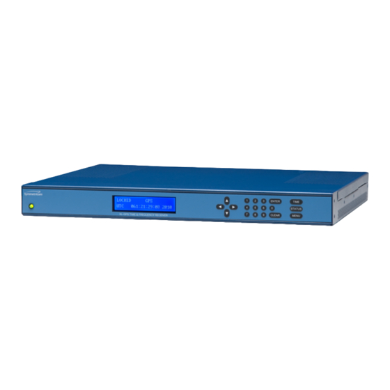
- Page 1 XL-GPS Time & Frequency Receiver User Guide CD Part Number 098-00116-000 Rev. A 5 May 2010...
-
Page 2: Notices
All rights reserved. Printed in U.S.A. All product names, service marks, trademarks, and registered trademarks used in this document are the property of their respective owners. The contents in this manual do not apply to previously released versions of XL-GPS hard- ware or software. -
Page 3: Preface
By purchasing any product manufactured by Symmetricom, the buyer consents to and agrees with Symmetricom that as a result of the exclusion of all warranties, expressed or implied, of merchantability, fitness for purpose, or otherwise, except for the limited one-year... -
Page 4: Proprietary Notice
Finding Answers to Product Questions For additional information about the products described in this guide, please contact your Symmetricom representative or your local sales office. You can also contact us on the web at www.symmetricom.com. -
Page 5: Table Of Contents
Limited Warranty Limitation of Liability Proprietary Notice About this Manual Finding Answers to Product Questions Table of Contents 1: Overview of the XL-GPS Time and Frequency Receiver Product Description and Features 2: System Specifications Chassis Environmental Time and Frequency Accuracy... - Page 6 Time Code Output IRIG-B000 200-04 W/ IEEE1344 Output: Time Code Inputs Time Code Outputs Time Code Input IRIG-B120 200-04 W/ IEEE1344 XL-GPS SYNC: Input: Time Code Input IRIG-B000 200-04 W/ IEEE1344 XL-GPS SYNC: GPS Time and Frequency Reference Summary of Options...
- Page 7 Making Additional Connections Make the following optional connections: Connecting the Power Supply CAUTION VAC power WARNING Removing Power CAUTION Stopping the XL-GPS Configuring the Network Port Configuring the Time Display Using the Command Line Interface Connecting to the Serial Port...
- Page 8 Rack Mounting the XL-GPS Grounding Proper Grounding Grounding the XL-GPS Installation Safety Considerations 4: User Interfaces Alarm Status LED Keypad Interface Time Display Status Display Menu Display Keypad Operation Keypad Examples Command Line Interface Logging In Operator Login Guest Login...
- Page 9 F71 – Oscillator Statistics F72 – Fault Status F73 – Alarm Control / Status F90 – Code Output Configuration F100 – Network Port Configuration & XL-GPS Firmware F100 EA – Ethernet Address F100 IP – IP Address F100 SM – Subnet Mask F100 G –...
- Page 10 F100 L – Remote Lockout Status F100 ST – Self Test Status F100 BH – Burn Host F100 BUB – Burn BootLoader F100 BU – Burn F100 BF – Burn File System F100 BUFP – Burn FPGA Firmware F100 CONFIG – Configure NTP & SNMP F100 J –...
- Page 11 Alarm Rates Optional Programmable Pulse Alarm Relay (87-8134-2) Installing the Expansion Module Configuring the Expansion Module Multicode Output (87-6002-XL1) Specifications Installation Adjusting Amplitude and Modulation Ratio 10 MHz Sine Output LPN Option Card (87-8114) 1, 5, 10 MHz Sine/MPPS Square Output (87-8108) Introduction Specifications 1 MHz Output:...
- Page 12 Set up the FTP Server Open a Command Line Session on the XL-GPS Upgrade the Firmware Troubleshooting C: SNMP SNMP Private Enterprise MIB Structure SNMP Addressing New Top Level Structure of Enterprise MIB for XL-GPS XL-GPS System Group The XL-GPS Fault Group...
- Page 13 Configuring and Testing SNMP HP OpenView Configuration XL-GPS Configuration Test Procedure D: Network Time Protocol (NTP) Editing ntp.conf Editing MD5 keys on the XL-GPS Editing MD5 keys on the NTP Client E: Time Code Formats Overview IRIG Introduction IRIG Code Format...
-
Page 15: 1: Overview Of The Xl-Gps Time And Frequency Receiver
Frequency Receiver Product Description and Features The XL-GPS Time and Frequency Receiver is high-precision time and frequency instrument that generates time and frequency outputs from its GPS-disciplined system clock. When locked to Symmetricom’s timing-optimized GPS receiver, the XL-GPS provides 1x10 frequency output accuracy, and better than 30 nS RMS accuracy to UTC. - Page 16 1: Overview of the XL-GPS Time and Frequency Receiver In addition, the following software-enabled optional features can be purchased and enabled using a software key at any time: • Network Time Server (NTS) • Programmable Pulse Output (PPO) • Time Interval, Event Time (TI/ET) •...
-
Page 17: 2: System Specifications
Chassis 2: System Specifications Chassis The chassis is a 19-inch rack-mounted 1U chassis. Size: 1.75 in. x 17.1 in. x 14. in. Weight: 8 lbs Standard Hardware: Standard 19" EIA rack system Optional Hardware: Slide rack hardware 098-00116-000 Rev. A....... Page 3 of 221... -
Page 18: Environmental
Symmetricom recommends leaving 1.4 in. (3.6 cm) above and below the XL-GPS or enough space to allow 5 CFM. AVERTISSEMENT : Installez le XL-GPS pour permettre un flux d'air autour et a travers l'unité. Symmetricom recommande de laisser 1.4 in. (3.6 cm) au-dessus et au-dessous du XL-GPS ou assez d'espace pour permettre 5 CFM. -
Page 19: Ac Power Supply
AC Power Supply AC Power Supply Input Description Universal type VAC Power supply Physical dimensions 5.00" x 3.00" x 1.26" Enclosed-Frame Package Input connector IEC 320 type Input voltage range Universal, 90 - 264 VAC / 120-370 VDC Input frequency range 47 Hz - 63 Hz Inrush Current 25A @ 115VAC / 50A @ 230 VAC and 80% load... -
Page 20: Network Port 10/100
2: System Specifications 5------GND 6------Rx- (RS-422) 7------Rx+ (RS-422) 8------Tx- (RS-422) 9------Tx+ (RS-422) Factory settings for RS-232 9600,N,8,1 Network Port 10/100 The Ethernet port interface is: Type: Standard RJ-45 8 pin connector, 10 Base-T and 100 Base-T standards. Frame format: IEEE 802.3 J1 - Optional TI/ET The TI/ET configuration is via the Keypad, Serial I/O, and Network port. -
Page 21: J2 - Rate Out
2V +/- 10% into 50 W J3 – Optional Frequency Measurement The Frequency Measurement (Freq Meas) option: measures an external frequency applied to the J3 input relative to the XL-GPS’ disciplined frequency. Frequency: 1, 5, 10 MHz 120 x 10... -
Page 22: Pps Out
2: System Specifications 1 PPS Out A time-stable 1 PPS (one pulse per second) output is provided. If no reference is available, the 1 PPS pulse will be as stable as the internal oscillator. Pulse width: 20 mS +/-1 mS On time edge: Rising Accuracy:... -
Page 23: Alarm
This mode of operation allows proper maintenance of UTC by the XL-GPS when utilizing a time reference source that does not contain leap second data. Manual leap second entry could also be beneficial when operating in a "free- run"... -
Page 24: Discrete 10 Mhz Output
2: System Specifications from the front panel keypad, the function is selectable by: 1. Menu 2. Up arrow to F67, Enter 3. Request the current GPS leap second, (e.g. January 2010: GPS time - UTC = -15, TAI - UTC = -34). Use the Up/Down keys to increment or decrement these values. (see a descrip- tion of International Atomic Time, TAI below). -
Page 25: Discrete 1Pps Output
Standard Features –11 Assuming the input carrier to be 5 x 10 Accuracy referenced to the carrier: 1 x 10 –11 Frequency/Timing Allan Deviation assuming the input carrier to be 3 X 10 @ 10 Stability: 5 x 10 @ 10 sec International Atomic Time (TAI) is the primary international time standard from which other time standards, including UTC, are calculated. -
Page 26: Output
Connector: BNC female Phasing: In phase with the XL-GPS 1PPS ± 10 mS Time Code Output IRIG-B000 200-04 W/ IEEE1344 The selectable Code output provides a selection for IRIG-B-000 w/ IEEE1344, (IRIG A000 and NASA 36 are also available as outputs). Configuration is made via the:... -
Page 27: Output
TTL into 50 Ω Qty: Connector: BNC female Phasing: In phase with the XL-GPS 1PPS ± 200ns Time Code Inputs The Code input configuration is via the Keypad / Display, RS232/422 and the Network port. The specifications are: AM or DC code IRIG-A-130 AM –000 DC, B-120 AM –000 DC,... -
Page 28: Time Code Input Irig-B120 200-04 W/ Ieee1344
IEEE1344 as defined in IEEE Std C37.118™-2005 ANNEX F as: (see section 3.3 def- inition) XL-GPS SYNC: The XL-GPS shall first synchronize to IRIG-B-120 w/ IEEE1344 when the Time Quality control bits are = 0000. The XL-GPS shall remain synchronized (Locked) while the Time Page 14 of 221 .........098-00116-000 Rev. A... -
Page 29: Input
Standard Features Quality control bits are 0000 through 0101 (ETE < 10uSec). The XL-GPS shall utilize the IRIG-B-120 BCDTOY ,IEEE1344 year, leap second, and leap second pending bit as the UTC epoch. The XL-GPS time format selection shall remain including the Daylight saving time offset. -
Page 30: Gps Time And Frequency Reference
Antenna power: +12 VDC Summary of Options The following options are available with the XL-GPS. For more information, go to the cross references associated with each one Expansion Module (87-8134-1) The expansion module provides four independently-configurable outputs. The outputs are configured using jumper/switch settings on the Expansion Module. -
Page 31: Mhz Sine And Mpps (87-8108)
For more informationSee "Oscillators" on page 18 Network Time Protocol (Option) The XL-GPS' can function as a Network Time Protocol (NTP) server when the Network Time Server (NTS) option is installed. With the NTS option, the XL-GPS Network Time Server processes NTP requests from networked clients and synchronizes to UTC as provided by the XL-GPS reference clock. -
Page 32: Oscillators
2: System Specifications The XL-GPS Network Time Server will respond to time synchronization requests from hosts using these User Datagram Protocol/Internet Protocols (UDP/IP): NTP ver. 3/4 UDP Port 123 - RFC1305 (Transmitted Timestamp Accuracy ±10 µS) SNTP UDP Port 123 - RFC1361... -
Page 33: Emc
This unit does not contain user-serviceable parts and does not require calibration. Volatility Statement See "I: Certificate of Volatility" on page 206 for the XL-GPS. Default parameters are stored one at a time through the function commands within the XL- GPS CPU module (089-00205-000). -
Page 35: 3: Installation/Configuration
Installing the GPS Antenna 3: Installation/Configuration Installing the GPS Antenna For XL-GPS units include a standard GPS receiver, antenna, and antenna cable. Install as described below. Selecting a GPS Antenna Site Outdoors Select a site that... • Is the highest point available •... -
Page 36: The Antenna
Use guy wires to stabilize masts longer than 10 ft. (3.048 m). The antenna Notes: • The XL-GPS requires a 12 Volt-compatible antenna. Antennas not rated for 12 V will be damaged. • Use an antenna splitter to connect a single antenna to multiple receivers. Don’t use a BNC “T”... -
Page 37: Gps Signal Strength Requirements
Additionally, if changing the antenna, abide by the 41 dB gain requirement. Other factors, such as radiation, coverage, VSWR, and input impedance also affect system performance. Symmetricom recommends using the standard antenna and cable provided with the GPS receiver. - Page 38 3: Installation/Configuration Figure 2: GPS Signal Strength Requirements Page 24 of 221 .........098-00116-000 Rev. A...
-
Page 39: Warning Gps Position And Altitude
Observe local codes and regulations. Use a lightning arrestor when needed. Antennas not rated for 12 VDC may be damaged when connected to the XL-GPS. The GPS antenna supplied with the XL-GPS is rated for 12 VDC. Safe Antenna and Cable Connection: An outside antenna or cable system must be properly grounded to provide some protection against built up static charges and voltage. - Page 40 Observez des codes et des règlements locaux. Utilisez un "arrestor" d'éclair quand nécessaire. Les antennes qui n'ont pas étés évalués pour un courant de 12 VDC peuvent être endommagées quand ils sont connectés au XL-GPS. Page 26 of 221 .........098-00116-000 Rev. A...
-
Page 41: Making Additional Connections
En installant une antenne, ne touchez jamais les lignes électriques ou d'autres sources d'énergie, sous peine de danger d'électrocution mortelle. Making Additional Connections Rear panel view of XL-GPS instrument Close-up of rear panel connections Note: The option card 87-8108 is shown installed in this image. -
Page 42: Make The Following Optional Connections
“F113 – J3 Input (Freq Meas)” on page 138 Connecting the Power Supply Connect the Power Supply to a power source. Upon receiving power, the XL-GPS goes through its startup sequence; displaying “Booting”, Loading”, and then “Starting”. After approximately 40 seconds, the XL-GPS displays the clock status, and user interfaces (front panel/command line) become available. -
Page 43: Warning Removing Power
Configuring the Network Port imentation d'énergie doit être seulement opérée à 100 - 240 VCA, 50-60 hertz. Relier le XL-GPS à une prise de courant avec contact adéquat de mise à la terre. WARNING Removing Power Prior to removing the top cover, disconnect all power connections. -
Page 44: Configuring The Time Display
F2 – 12/24-Hour Format: (“F2 – 12/24 Hour Format” on page 50) Select a 12 or 24- hour display format. By default, the XL-GPS is set to the 24-hour display format (e.g., 6 P.M. is displayed as 18:00). • F66 – Daylight Saving Time (DST): (“F66 –... -
Page 45: Using The Command Line Interface
Using the Command Line Interface The next two sections show how to connect to the XL-GPS using the serial and network ports. Both Serial I/O and the network port give the user access to the command line interface. While the keypad interface provides a simple menu-driven user interface, the command line interface features: •... -
Page 46: Connecting To The Network Port
3: Installation/Configuration Initiate a serial port connection between the terminal emulation program and the XL-GPS. (The Serial Port connection does not require you to log in.) Once connected, press the Enter key on your keyboard to get a command prompt. -
Page 47: Rack Mounting The Xl-Gps
To troubleshoot a problematic Antenna installation, recheck the physical location of the antenna, the cabling, and the configuration settings described in this manual. Rack Mounting the XL-GPS The XL-GPS comes with the following parts needed to mount the XL-GPS securely in any EIA standard 19-inch (48.26-cm) rack: •... -
Page 48: Grounding
Proper Grounding Maintain reliable grounding (earthing) of rack-mounted equipment. The ground screw provided with the XL-GPS instrument, is a stainless steel, pan head, 10- 32, 0.375 inch long, machine screw. Grounding the XL-GPS For VAC power, verify that a properly grounded three-prong outlet is available for the standard power cord. -
Page 49: Installation Safety Considerations
Reduced Air Flow: Position the XL-GPS with enough space above, below, and adjacent to the chassis to allow an adequate flow of air so that it may operate safely. Symmetricom rec- ommends leaving 1.4 in. (3.6 cm) above and below the XL-GPS or enough space to allow 5 CFM air flow. -
Page 51: 4: User Interfaces
A command line interface available through the serial and network ports There is also an Alarm Status LED on the front panel. Alarm Status LED The Alarm Status LED, located on the front panel, displays the alarm-state of the XL-GPS unit. The LED has four states: Dark = Power is off. -
Page 52: Status Display
“F66 – Daylight Saving Time (DST) Mode” on page 84 Status Display The Status Display comes up automatically when the XL-GPS is rebooted. To manually switch from another display to the Status Display, press STATUS button on the keypad. The keypad appears as follows: <STATUS>... -
Page 53: Menu Display
See “Time Display” on page 37. 200:21:24:09 2009 = The time, in DDD:HH:MM:SS YYYY format ( Menu Display To use the XL-GPS functions that are available from the keypad, press the MENU button on the keypad. “Function Summary” on page 45 lists which functions are available from the Menu Display. -
Page 54: Keypad Examples
4: User Interfaces Enter numeric values ENTER Enters currently displayed choice, e.g., a function or yes/confirmation to save changes Clears the current selection/choice and returns to the last saved value TIME Displays the current time. Can also be used to exit a function without saving changes. STATUS Displays the clock status and time. -
Page 55: Command Line Interface
Will change “0” to “1”, if the second number is 2 or less. For UP ARROW example 01 wil become 11, but 08 will not become 18. ENTER XL-GPS asks “SAVE CHANGES? YES” UP ARROW Changes “YES” to “NO” ENTER... -
Page 56: Logging In
“operator” and “guest”. The serial port’s command line interface does not require the user to log in. Operator Login The Operator has full privileges to change the settings in all the XL-GPS’s functions and to perform firmware updates. As shipped, you can log in as Operator using: User Name: operator Password: janus To maintain security, change the Operator password at installation. -
Page 57: Session Timeout And Priority
Session Timeout and Priority The XL-GPS’s system firmware has session timers that will terminate an inactive command line session on the network port after 15 minutes. The XL-GPS does not terminate inactive command line sessions on the serial port. The user can open a network port session and a serial ports session concurrently, provided the other session is inactive (i.e., not actively performing a function such as See "F8 –... - Page 58 4: User Interfaces >NOTICE: UTILITY MONITOR SESSION HAS TAKEN PRIORITY FROM THIS TELNET SESSION! >f100 ic NOTICE: CANNOT RESPOND TO COMMAND BECAUSE UTILITY PORT SESSION HAS PRIORITY! Page 44 of 221 .........098-00116-000 Rev. A...
-
Page 59: 5: Function Reference
5: Function Reference Function Summary The following summary lists all the XL-GPS functions, identifies the user interfaces from which each one is available, and provides a brief description of the function. Available from: K = keypad, N = Network Port (Telnet), S = Serial Port... - Page 60 *Locked through the network port, serial port, and keypad. Status Can be unlocked only through the keypad or serial port. F100 ST – Self Test Display the XL-GPS’s self test results for Flash CRC, K, N, S Status RAM, Serial Port, and NVRAM Upgrading system firmware: select the FTP host, path, F100 BH –...
- Page 61 F100 P – Change User N, S Change the XL-GPS password Password F100 PI – PING N, S Ping from the XL-GPS to another host on the network F100 PN – Change User N, S Change the User Name Name F108 – Oscillator...
-
Page 62: F1 - Time Zone Offset
“F11 – Time Output Format” on page 64 See "F11 – Time Output Format" on page 64 Command Line To display the time zone offset, send: F1<CR> XL-GPS responds: F1<S><SIGN><HH>:<MM><CR><LF> where: = ASCII character F = function number = ASCII space character (one or more) <S>... - Page 63 = two-digit minutes offset <CR> = carriage return character = line feed character <LF> For example, to set the time zone offset, enter: F1 –8:00<CR> XL-GPS responds: OK<CR><LF> To verify the change, enter: F1<CR> XL-GPS Responds: F1 –8:00<CR><LF> 098-00116-000 Rev.
-
Page 64: F2 - 12/24 Hour Format
The factory settings for F2 are 24-hour format for the display and 24-hour format for IRIG (F90) Command Line To display the current hour format, send: F2<CR> XL-GPS responds: F2<S>D<HH><SEP>I<HH><CR><LF> where: = ASCII character F. = Function number. = ASCII space character (one or more). - Page 65 = ASCII character for IRIG format <CR> = Carriage return character. <LF> = Line feed character. For example, to display the current hour format, send: F2<CR> XL-GPS responds: F2 D24 I24<CR><LF> To set the hour format, send: F2 D12 I24<CR> XL-GPS responds: OK<CR><LF>...
-
Page 66: F3 - Time & Date
10:47 PST, which is only 5 hrs, not 8 with F1 set to –8:00. F3 defines only the entry of tim in F3; it does not control the type of time displayed or output by the XL-GPS. F3’s Time Mode should not be confused with F69 (see “F69 –... - Page 67 <LF> = line feed character. For example, to display the date and time, send: F3<CR> XL-GPS responds: F3 UTC 01/01/2009 00:05:34<CR><LF> To set the time and date, send: F3 UTC 07/14/2009 18:20:30<CR> Note: Only valid times and dates are accepted.
-
Page 68: F4 - Serial Port Configuration
• Stop bits – 1 See "Factory Default Jumper and Switch Settings for Options" on page 166 Command Line To display the Serial Port settings, send: F4<CR> XL-GPS responds: F4<S><RS><SEP><BR><SEP><DB><SEP><P><SEP><SB><CR><LF> where: = ASCII character F. = function number. <S> = ASCII space character (one or more). - Page 69 Note: Parity - NONE is only available/valid when Data Bits is set to 8. For example, to display the serial port settings, send: F4<CR> XL-GPS responds: F4 232 9600 8 none 1<CR><LF> To set the serial port settings, send: F4 422 9600 7 even 1<CR>...
-
Page 70: F5 - Time-Quality Setup
The XL-GPS estimates time error based on the oscillator-type and on the degree of steering (the DAC value) that was being applied to the oscillator before the timing reference became unavailable. - Page 71 <LF> = line feed character For example, to display the time quality status and flags, enter: F5<CR> If F5 is enabled, XL-GPS responds (example): F5 ENABLE 00000001000 00000010000 00000100000 00001000000<CR><LF> If F5 is disabled, XL-GPS responds: F5 DISABLE<CR><LF> To enable time quality reporting, and change the thresholds of the time quality flags, enter: F5 ENABLE 2000 20000 200000 2000000<CR>...
-
Page 72: F6 - Keypad Lock
The factory setting for F6 – Keypad Lock is disabled. See "Factory Default Jumper and Switch Settings for Options" on page 166 Command Line To display the Keypad Lock status, send: F6<CR> XL-GPS responds: F6<S><STATE><CR><LF> where: = ASCII character F = function number = ASCII space character (one or more) <S>... - Page 73 F6 – Keypad Lock To disable Keypad Lock, send the following string: F6 DISABLE<CR> XL-GPS responds: OK<CR><LF> 098-00116-000 Rev. A....... Page 59 of 221...
-
Page 74: F8 - Continuous Time Once-Per-Second
In the first two lines above, the unsynchronized time is followed by a “?” time quality character. In this case, the “?” indicates that the XL-GPS is unlocked to a reference source. As the XL-GPS locks to the reference source, the “?” disappears, and after a couple seconds, the new synchronized time-of-year information appears. - Page 75 “F13 – Time Error” on page 67 for more information. Command Line For example, to initiate Continuous Time once-per-second, enter F8<CR> The XL-GPS replies: 199:11:19:30<CR><LF> 199:11:19:31<CR><LF> 199:11:19:32<CR><LF> To stop Continuous Time Once-Per-Second, press Ctrl-C on your keyboard to stop it. 098-00116-000 Rev.
-
Page 76: F9 - Time On Request
Note: This function is available through the command line interface only – it is not available through the keypad. Use function F9 to record the exact time the XL-GPS receives a request from the user. Enter the command “F9<CR>” to prepare the XL-GPS for the user’s request. At the desired moment, send the request to the XL-GPS by entering an upper case “T”. - Page 77 For example, to prepare Time on Request, enter: F9<CR> Then, to request the current time, enter SHIFT-T on your keyboard. (“T” does not appear on the command line). XL-GPS responds: <SOH>128:20:30:04.357*<CR><LF> To exit F9 press Ctrl-C on your keyboard. 098-00116-000 Rev.
-
Page 78: F11 - Time Output Format
5: Function Reference F11 – Time Output Format Use function F11 to review or change the format of the time output string used in F8. The as- shipped factory setting for F11 format is null, which enables F8’s default time output formats. The default format for F8 –... - Page 79 To see the Time Output Format, enter: F11<CR> XL-GPS responds: F11 DDD:HH:MM:SS.mmmQ<CR><LF> To remove the day, hour, minute, second, microsecond, or a character from the time output format (other than the ASCII <SOH> <CR> or <LF> characters), enter the following string replacing the character you want to remove with an “X”:...
- Page 80 If you end the first part of a format string early with a carriage return, the remaining un-typed characters are enabled and assume their default values. For example, if you enter: F11<TAB>XXX|<CR> XL-GPS responds: OK<CR> With the above settings, F8 displays: <SOH>|10:45:01*<CR><LF>...
-
Page 81: F13 - Time Error
Time error begins to accumulate when the receiver loses lock to a reference source. The XL-GPS calculates the worst-case time error based on the stability of system clock’s oscillator type, and the time elapsed since loss of lock. -
Page 82: F18 - Software Version Request
• FPGA Command Line Use Command Line Function F18 to obtain the system’s firmware version information.For example, enter: F18<CR> XL-GPS responds: F18 BOOTLOADER 084-00251-000V1.82.1.15 SOFTWARE 084-00217-000V1.82.1.15 FILE SYSTEM 084-00359-000V1.82.1.15 PROJ REV # 2-1 FPGA # 084-00360-000V65 Page 68 of 221 .........098-00116-000 Rev. A... -
Page 83: F42 - Multicode Output Configuration
F42 - Multicode Output Configuration F42 - Multicode Output Configuration SERIAL/NETWORK FUNCTION F42 – MULTICODE OUTPUT SETUP Use Serial/Network Function F42 to setup the output on the Multicode output card. Use the following ASCII string to request the card number of the installed card: F42<CR>... - Page 84 5: Function Reference O = ASCII letter indicating output port. <C> = channel number, 1 to 4. <CODE>= IRIG B 120, IRIG B 123, IRIG E 111, IRIG E 112, IRIG E 121, IRIG E 122, IRIG H 111, IRIG H 112, IRIG H 121, IRIG H 122, 2137, XR3, NASA 36 IRIG-A 133 (will be applied to all IRIG-A assigned ports) IRIG-G 141 (will be applied to all IRIG-G assigned ports)
- Page 85 F42 - Multicode Output Configuration The Serial/Network port will respond with the Time Reference for the Multicode output card. The following example requests the Time Reference for the Multicode output card: F42 T<CR><LF> The Serial/Network port will respond with the following string: F42 UTC<CR><LF>...
-
Page 86: F50 - Gps Receiver Lla/Xyz Position
5: Function Reference F50 – GPS Receiver LLA/XYZ Position Use function F50 to display the current GPS position. Specifically, use function F50 to: • Select the positional coordinate system: LLA (Latitude Longitude Altitude) XYZ (Earth-Centered, Earth-Fixed (ECEF XYZ) coordinates based on WGS 84). - Page 87 Altitude is displayed in meters above (“+”) or below (“-”) the WGS 84 ellipsoid. Command Line Use the following format to display the current settings display the current position for the GPS receiver in LLA coordinates: F50<S>LLA<CR> XL-GPS responds with the coordinate information in the following format: F50<S><SIGN><S><DEG>d<MIN>'<SEC>"<S><SIGN><S><DEG>d<MIN>'<SEC>"<S><ALT><- UNITS><CR><LF> where: = Function 50 = ASCII space character one or more.
- Page 88 XL-GPS responds (example): F50 N 38d23'51.3" W 122d42'53.2" 58m<CR><LF> To display the present antenna position using ECEF XYZ coordinates in meters, use the following format: F50<S>XYZ<CR> XL-GPS responds using the following format: F50<S><SIGN><S><MX>m<S><SIGN><S><MY>m<S><SIGN><MZ>m<CR><LF> where: = ASCII character F = function number = ASCII space character <S>...
-
Page 89: F51 - Gps Antenna Cable Delay
For RG-58: multiply the cable length by 1.4 ns/ft. to get the value for F51. • Don’t use function F51 to adjust the XL-GPS’s timing outputs; use F52 Distribution Cable Delay instead. See "Factory Default Jumper and Switch Settings for Options" on page 166... - Page 90 5: Function Reference F51<CR> XL-GPS responds: F51 +000060ns<CR><LF> To set the antenna cable delay, use the following format: F51<S><DELAY>NS<CR> For example, to set the antenna cable delay to 100 nS, enter: F51 100NS<CR> XL-GPS responds: OK<CR><LF> Page 76 of 221 .........098-00116-000 Rev. A...
-
Page 91: F52 - Distribution Cable Delay
Use function F52 to display or set the distribution cable delay for the standard CODE (time code) and 1 PPS outputs. F52 compensates for the signal’s travel time from the XL-GPS to its point of use. The distribution cable delay applies uniformly to all output ports. The as- shipped factory setting is +0 ns. - Page 92 5: Function Reference XL-GPS responds: F52 +000000ns<CR><LF> To set the distribution cable delay to 60 nS, enter: F52 +000060nS<CR> XL-GPS responds: OK<CR><LF> Page 78 of 221 .........098-00116-000 Rev. A...
-
Page 93: F53 - Gps Operation Mode
Select “Dynamic Mode” if the position of the receiver is subject to frequent change, or if it is in continuous motion. For example, use Dynamic Mode when the XL-GPS is used in mobile vehicles such as ships, land vehicles, or aircraft. With Dynamic Mode selected, the receiver updates the position information repeatedly to arrive at the best time calculations for a mobile environment. - Page 94 5: Function Reference F53<CR> F53 responds using the following format: F53<SP><SEP><STATUS><CR><LF> where: = ASCII character F (f or F for input string). = the function number. <SP> = ASCII space character one or more. = one or more space characters. <SEP>...
-
Page 95: F60 - Gps Receiver Satellite List
Use function F60 to display the identification number and signal strength of tracked or current satellites. ‘Tracked’ means a satellite’s signal is being received and interpreted by the receiver (or that the XL-GPS has GPS data that suggests this satellite should be visible to the antenna). - Page 96 5: Function Reference <CR> = Carriage return character. = Pseudo Random Number = 1 through 32 (prn<NN> identifies specific GPS satellites) <NN> <STATE> = Good, Bad, or Unknown tracked = Either “tracked” or blank current = Either “current” or blank <LEVEL>...
- Page 97 F60 – GPS Receiver Satellite List F60 prn32 unknown Similarly, to display a list of the current, tracked, bad or rejected satellites, enter: F60 CURRENT<CR> F60 TRACKED<CR> 098-00116-000 Rev. A....... Page 83 of 221...
-
Page 98: F66 - Daylight Saving Time (Dst) Mode
5: Function Reference F66 – Daylight Saving Time (DST) Mode Use function F66 to enable or disable Daylight Saving Time (DST), and to schedule when Local time enters and leaves DST. The factory setting for F66 is Manual (i.e., DST On). The hour for entering/leaving DST is given in the 24-hour format. - Page 99 OK<CR><LF> Meaning that Local time will enter DST on the last week of the month. All other parameters remain unchanged. The XL-GPS automatically reboots when the user changes the DST entry/exit times in F66. 098-00116-000 Rev. A....... Page 85 of 221...
- Page 100 5: Function Reference If any of the items in an input string are invalid, an error message will be returned. Page 86 of 221 .........098-00116-000 Rev. A...
-
Page 101: F67 - Manual Leap Seconds Entry/Request
F67 – Manual Leap Seconds Entry/Request F67 – Manual Leap Seconds Entry/Request Use Serial/Network Function F67 to manually enable a leap second insertion into the XL- GPS clock time structure. To request the present status of the manual leap seconds settings, send F67<CR>... - Page 102 5: Function Reference F67 <SP>TAILS<SEP><-nn> where: TAILS = ASCII string indicating a TAI Epoch leap second value will be entered. <-nn> = Leap second valued entered, -19 to –49. Sample entry: F67 TAILS -33<CR> Response: OK<CR><LF> Adding a Leap Second: To set the next leap second insertion time for adding a leap second, enter a continuous string of the form: F67 <SP>ADD<SEP><MONTH><SEP><YEAR>...
- Page 103 F67 – Manual Leap Seconds Entry/Request F67 <SP>NONE<CR> where: NONE = ASCII string indicating a manual leap second insertion function will be disabled. The Serial/Network port will respond with the message “ERROR 01 VALUE OUT OF RANGE” if the input string was in the correct format but contained a value, probably numeric, that was out of the range of acceptable values.
-
Page 104: F69 - Time Mode
5: Function Reference F69 – Time Mode Use function F69 to select the time type displayed by: See "F1 – Time Zone Offset" on page 48 Select between the following types of time: • UTC (Coordinated Universal Time) differs from GPS Time by the addition of leap- second corrections to compensate for variations in the earth’s rotation. - Page 105 F69 – Time Mode For example, enter: F69<CR> XL-GPS gives one of the following responses: F69 GPS <CR><LF> F69 UTC <CR><LF> F69 LOCAL <CR><LF> F69 STANDARD <CR><LF> To set the time mode, enter a command using the following format: F69<S><TT><CR>...
-
Page 106: F71 - Oscillator Statistics
5: Function Reference F71 – Oscillator Statistics Use F71 to display the phase, frequency offset, drift rate, and DAC value of an internal or optional external oscillator. Definitions: The phase is the instantaneous error in seconds between the oscillator and the control loop zero servo point. - Page 107 F71 – Oscillator Statistics For example, enter F71<CR> F71 responds: F71 PHASE=-5.678E-09 s OFFSET=-1.986E-07 DRIFT= 6.013E-08/DAY DAC=24567<CR><LF> 098-00116-000 Rev. A....... Page 93 of 221...
-
Page 108: F72 - Fault Status
5: Function Reference F72 – Fault Status Use function F72 to display the fault status of the clock. • Clock PLL – Locked or unlocked • Clock Status – Locked or unlocked Command Line To display the status of the fault detectors, enter: F72<CR>... -
Page 109: F73 - Alarm Control / Status
The following table summarizes F73’s alarm indicators and parameters, as well as the factory settings for an XL-GPS without options. The factory settings vary depending on the options included at the XL-GPS at the time it ships from the factory (see... - Page 110 Suppress” on page 98. Alarm Definitions Clock Status Locked: The XL-GPS clock is locked to the GPS reference source and is operating within the F73 Time Error Threshold. Unlocked: Check the other alarm indicators to determine the cause of the problem.
- Page 111 The LPN (Low Phase Noise) PLL indicator reports “Locked” during normal operation while the LPN oscillator on an LPN Card is locked to the XL-GPS’s internal oscillator. The LPN PLL indicator reports “Unlocked” for several minutes after the unit is started while the LPN oscillator on the card warms up.
- Page 112 5: Function Reference Locked: The DAC, which disciplines the clock oscillator to the reference source, is operating nominally. Unlocked: The DAC is operating out of specifications. Return to Symmetricom for service. “H: Sales and Customer Assistance” on page 204. 1st Time Lock...
- Page 113 F73 – Alarm Control / Status Use Clear Alarm Latch after troubleshooting or fixing the cause of an alarm so new alarms can be distinguished from previous ones. About Alarm Latch: The Alarm Latch shows if an indicator has triggered an alarm at any time since the last time the Alarm Latch was cleared, even if the indicator is presently “Locked”...
- Page 114 5: Function Reference = ASCII character ‘P’ - static character, does not indicate status. = '-' PLL Synthesizer Locked 'C' PLL Synthesizer Unlocked = '-' LPN PLL Locked 'L' LPN PLL Unlocked = '-' GPS OK 'P' GPS fault = '-' not used = '-' IRIG OK 'I' IRIG Fault = '-' not used...
- Page 115 To enable ('E'), disable (‘D’), or leave the indicator unchanged (‘-’), enter 'E', 'D', or '-' for each character in <123456789ABCDEFGHIJ> when you enter the following string: F73<SP>MASK<SEP><123456789ABCDEFGHIJ><CR> The XL-GPS will sets the new alarm mask and responds: OK<CR><LF> The following summarizes the fault alarm mask setting in the <123456789ABCDEFGHIJ>...
- Page 116 Query or set Time Error Threshold using the THRESHOLD command. To query the Time Error Threshold setting, enter: F73<SP>THRESHOLD<CR><LF> The XL-GPS responds: F73<SP>THRESHOLD<SP><nanoseconds><SP>ns<CR><LF> where <nanoseconds> is the time error threshold in nanoseconds, between 0 and 9999. To set Time Error Threshold, enter a string the following format:...
- Page 117 F73 – Alarm Control / Status F73<SP>THRESHOLD<SEP><nanoseconds><CR> The XL-GPS will set the new time error threshold and returns the following string if the command is successful. OK<CR><LF> Set or query Timeout Delay using the TIMEOUT command. To query the current setting, enter: F73<SP>TIMEOUT<CR><LF>...
- Page 118 <CR> = Line Feed. <LF> To set the SUPPRESS enter a command using the following format: F73<SP>SUPPRESS<SEP><seconds><CR> The seconds can be set to any value from 0 to 86400. The XL-GPS responds: OK<CR><LF> Page 104 of 221 .........098-00116-000 Rev. A...
-
Page 119: F90 - Code Output Configuration
F90 – Code Output Configuration Use function F90 to configure the time code output format (IRIG-A, IRIG-B, IRIG-B120 IEEE 1344 or NASA 36) and modulation type (AM or DC) on the XL-GPS’s standard CODE output. The factory settings for F90 are IRIG-B and AM. - Page 120 5: Function Reference To change the Code Output selection enter: F90 IRIG-B DC<CR> XL-GPS responds: OK<CR><LF> Sample request for Time Code Out with IEEE 1344 extensions: F90<CR> Response: F90 IRIG-120 1344 To enter the Code Output selection, send the following character string to the Serial/Network port: Sample entry: F90<SP>IRIG-B DC<CR>...
-
Page 121: F100 - Network Port Configuration & Xl-Gps Firmware
NTP & SNMP parameters, changing the user name/password, resetting the unit, and pinging other network devices. Warning: The F100 commands have the capacity to remove the XL-GPS from the network and disable the XL-GPS’s system firmware. Use judiciously. - Page 122 5: Function Reference The following table gives the command line equivalents for each of the preceding parameters: Description “F100” followed by: Comments Ethernet address Displays information (MAC address) IP Address Displays, configures and reboots Subnet Mask Displays, configures and reboots Default Gateway Displays, configures and reboots IP Address, Subnet Mask,...
-
Page 123: F100 Ea - Ethernet Address
The first three bytes are registered to Symmetricom Inc.; the last three bytes are the hex value identifying the network port. To display the Ethernet address of the unit standard network port, enter: F100 EA<CR>... - Page 124 PLEASE WAIT…<CR><LF> To obtain the IP address of the unit Standard network port, enter: F100 IP<CR> XL-GPS responds (example): F100 IP 206.54.0.21<CR><LF> The three commands, F100 IP, F100 SM, and F100 G, can be concatenated to set all three values simultaneously. To do so use the following format: F100<S>IP<S><nnn.nnn.nnn.nnn><S>SM<S><nnn.nnn.nnn.nnn><S>G<S><nnn.nnn.nn-...
-
Page 125: F100 Sm - Subnet Mask
F100 – Network Port Configuration & XL-GPS Firmware F100 SM – Subnet Mask Note: F100 SM can be used concurrently with F100 IP and F100 G. See the last example provided in the F100 IP – IP Address section, directly above this one. -
Page 126: F100 G - Gateway
<nnn.nnn.nnn.nnn> = dotted decimal address (0 to 255) = input line terminator <CR> For example, enter: F100 G 206.54.0.17<CR> XL-GPS responds: OK<CR><LF> RESETING THE UNIT<CR><LF> PLEASE WAIT…<CR><LF> To obtain the Default Gateway of the unit Standard network port, enter: F100 G<CR>... -
Page 127: F100 Ic - Network Port Settings
F100 – Network Port Configuration & XL-GPS Firmware F100 IC – Network Port Settings Use function F100 IC to review the entire configuration of the standard network port, enter: F100<S>IC<CR> An example of the response is: F100 IP:206.54.0.21 SM:255.255.255.240 G:206.54.0.17<CR><LF>... -
Page 128: F100 L/Lock/Unlock - Remote Lockout
F100 LOCK<CR> To users on the serial port, XL-GPS responds: OK<CR><LF> Or, to users on the network port, XL-GPS gives the following response and then closes the port: GOODBYE.<CR><LF> To unlock remote lockout, use the command line interface on the serial port to enter: F100 UNLOCK<CR>... -
Page 129: F100 L - Remote Lockout Status
F100 – Network Port Configuration & XL-GPS Firmware F100 L – Remote Lockout Status Command Line Only – Not available in keypad. Use function F100 L to display the status of the remote lock. For more information, see F100 LOCK above. -
Page 130: F100 Bh - Burn Host
5: Function Reference = specify ST command <CR> = input line terminator XL-GPS responds: F100<S>ST<S>FLASH/C- RC:<S><STATUS>,<S>RAM:<S><STATUS>,<S>SERIAL:<S><STATUS>, <S>NVRAM<S>VER:<S><STATUS><CR><LF> where: = ASCII character F = Unit function number <S> = Space = Specify ST command FLASH/CRC: = Specify flash checksum result = Specify RAM test result RAM: = Specify Serial Port test result. -
Page 131: F100 Bub - Burn Bootloader
F100 – Network Port Configuration & XL-GPS Firmware Use UNIX style forward slashes ‘/’ in path and do not describe the drive (for example, ‘C’) in the path. For example: F100 BH 10.1.7.20 symmetricom/XL-GPS/192-8001.bin<CR> XL-GPS responds: BURN HOST IS READY!!!<CR><LF>... -
Page 132: F100 Bf - Burn File System
Flash memory is checked to ensure that the correct file is used. To write the file to the flash, send the F100 BH command with the FTP host, file path and name, and then enter: F100 BU<CR> XL-GPS responds: OK<CR><LF> And, for example, displays the following text: >f100 bu BURNING FILE 192-8001.bin WITH SIZE 803016 TO PARTITION:1 SECTOR:16... -
Page 133: F100 Bufp - Burn Fpga Firmware
FOR PARTITIONING (zzz BYTES), LOAD ABORTED" will be displayed, and the new program will not be loaded to the flash. After all the requirements for burning the FPGA program are met, XL-GPS will proceed to burn the FPGA program from the FTP host computer to the target flash by responding with the following output string. -
Page 134: F100 Config - Configure Ntp & Snmp
SEC: 11 RE: 0 FLASH SUCCESSFULLY PROGRAMMED To load the FPGA program from the target flash to the FPGA, a reboot of the XL-GPS is required for the new FPGA program to take effect. The XL-GPS can be rebooted via power cycle or by issuing the F100 K I L L command on the serial port interface. -
Page 135: F100 J - Factory Mode Jumper
To move the SNMP config file back onto the XL-GPS, type: >f100 config snmp set host:<IP Address> dir:<subdir><CR> To move the NTP and SNMP config files back onto the XL-GPS, type: >f100 config ntp snmp set host:<IP Address> dir:<subdir> Here’s an example of a successful SNMP and NTP config file transfer: >>f100 config set ntp snmp host:192.168.0.1 dir:... -
Page 136: F100 K I L L - Reboot
Symmetricom technicians to test and configure the unit. With this jumper installed, the operation and integrity of the XL-GPS are compromised. Warning: Do not run the XL-GPS with the jumper, unless specifically directed to do so by a qualified Symmetricom technician. -
Page 137: F100 P - Change User Password
In a network port session, rebooting the XL-GPS terminates the network port session; open a new network port session when the XL-GPS has finished rebooting. In a serial port session, the XL-GPS displays text similar to the following example when the XL-GPS has... -
Page 138: F100 Pi - Ping
Use function F100 PI to ping a remote host to see if it is reachable. If no IP Address is provided, F100 PI uses the XL-GPS’s own IP Address, and tests whether the XL-GPS’s network port has a good network connection. -
Page 139: F100 Pn - Change User Name
F100 – Network Port Configuration & XL-GPS Firmware To test if the XL-GPS’s network port has a good connection, enter the following using in a serial port session: >f100 PI<CR> XL-GPS responds: PING : REMOTE HOST FOUND.<CR><LF> or it responds: PING : REMOTE HOST NOT FOUND.<CR><LF>... - Page 140 F100 K I L L – Reboot command. • Immediately press the MENU key on the keypad and hold down while the XL-GPS is rebooting. The XL-GPS will display will ‘hang’ while displaying “BOOTING”. • After a few moments, release the MENU key.
-
Page 141: F108 - Oscillator Configuration
= Carriage Return, equivalent to pressing the Enter key on a keyboard <CR> <OSC> = Oscillator type: TCXO, OCXO For example, enter the following string: F108<CR> XL-GPS responds (example): F108 OSCILLATOR CONFIG TCVCXO<CR><LF> (or OCXO) 098-00116-000 Rev. A....... Page 127 of 221... -
Page 142: F110 - J1 Input (Time Code, Tiet)
F110 – J1 Input (Time Code, TIET) Note: Time Interval - Event Time (TIET) is an optional feature. If purchased at the same time as the XL-GPS, it comes enabled on the system. To purchase this option after you have purchased the XL-GPS, contact Symmetricom Sales. - Page 143 If the time code does not provide UTC in 24-hour format (e.g., it uses standard, local, or GPS time, or is in 12-hour format), the XL-GPS’s internal clock will be set to the wrong time when it uses the time code reference, and its time outputs will be similarly affected.
- Page 144 To set the J1 Input Configuration, make a command line entry using the same format as the XL-GPS response above. Only valid values are accepted. For example: F110 IRIG A SECONDARY 50 DC POSITIVE 1234 US SYNC GEN 1 FRAME<CR>...
- Page 145 F110 IRIG A STANDBY 50 DC POSITIVE 1234 US SYNC GEN 1 FRAME<CR> And then configure TIET (example): F110 TIET 100K POSITIVE<CR> The XL-GPS responds: OK<CR><LF> Note: Note: If the TIET is configured, the timestamp(s) of the rising edge of the J1input sig- nal will be displayed each second.
- Page 146 5: Function Reference <Code> = Input Code: IRIG-B120 1344 or IRIG-B000 1344 <Source> = Clock source: PRIMARY, STANDBY <Impedance> = 100K, 50 (50 ohm impedance is selectable with IRIG-B000/1344) type only) <Sign> = Code Sign: POSITIVE, NEGATIVE <Delay> = Propagation Delay: 0-99999uS <Mode>...
-
Page 147: F111 - J2 Output (Rate, Ppo)
10 PPS, 100 PPS, 1 kPPS, 10 kPPS, 1 MPPS, 5 MPPS, 10 MPPS, or PPO. The default factory setting is 10 MPPS. Note: PPO is an optional feature. If purchased at the same time as the XL-GPS, it comes enabled on the system. To purchase this option after you have purchased the XL- GPS, contact Symmetricom Sales. - Page 148 Line terminator: a carriage return and line feed for output strings, or a carriage return <CR><LF> = for input strings Sample request: F111<CR> The XL-GPS displays a fixed 10 PPS rate output (example): F111 RATE 10PPS<CR><LF> . Or, displays the PPO settings (example): F111 PPO 120:22:56:12.000000 120:22:56:12.000003<CR><LF> Setting the J2 Output Configuration To set the J2 Output Configuration, send a character string with the previously defined F111 entry format to the Serial/Network port.
- Page 149 F111 – J2 Output (Rate, PPO) For example, to produce a fixed 100 kPPS rate output, enter: F111 RATE 100KPPS<CR> XL-GPS responds: OK<CR><LF> Single PPO pulse output For example, to produce a a single pulse with duration of 1 second on January 1, enter: F111 PPO 001:00:00:00.000000 001:00:00:01.000000 <CR>...
- Page 150 5 pulse width), enter: F111 PPO XXX:XX:XX:XX.XXXXX0 XXX:XX:XX:XX.XXXXX5<CR> XL-GPS responds: OK<CR><LF> Or, for example, to produce a repetitive 50-microsecond pulse occurring every 100 microseconds (i.e., repetitive pulses with 10 kPPS frequency with the start time or rising-...
- Page 151 F111 – J2 Output (Rate, PPO) XL-GPS responds: OK<CR><LF> Or, for example, to produce a repetitive one-microsecond pulse occurring on every hour, enter: F111 PPO XXX:XX:10:00.000000<CR> XL-GPS responds: OK<CR><LF> 098-00116-000 Rev. A....... Page 137 of 221...
-
Page 152: F113 - J3 Input (Freq Meas)
F113 – J3 Input (Freq Meas) Note: Frequency Measurement is an optional feature. If purchased at the same time as the XL-GPS, it comes enabled on the system. To purchase this option after you have pur- chased the XL-GPS, contact Symmetricom Sales. - Page 153 F113 configuration is selected, or another function performed. Command Line To display the J3 Input Configuration, enter: F113<CR> XL-GPS responds as follows if the Freq Meas option has not been installed: F113<S>DISABLE<CR><LF> When the Frequency Measurement option is enabled, F113 responds: F113<S>FREQ MEAS<S><FREQ><S><IMP><S><INT><CR><LF>...
- Page 154 Or, to enable Freq Meas of a 1 MHz input with a 50 W input impedance every 1 seconds, enter: F113 FREQ MEAS 1MHZ 50 1<CR> To all three of the above examples, XL-GPS responds: OK<CR><LF> If enabling Freq Meas, display the Freq Meas measurements using the following format: F113<S>SHOW<CR>...
- Page 155 F113 – J3 Input (Freq Meas) XL-GPS responds using the following format: Interval<S>is<S><INT><S>seconds<CR><LF> +#.######e-##<CR><LF> Where ASCII character string “Interval is” Interval is ASCII space character or separator. <S> Frequency Measurement Interval <INT> seconds ASCII character string “seconds” ASCII plus “+” or minus “-” character ASCII integer from 0 to 9 ASCII characters “e-”...
-
Page 156: F117 - Factory Configuration
5: Function Reference F117 – Factory Configuration Use function F117 to display the XL-GPS factory Serial Number and the availability optional software features. Send the string: F117<CR> XL-GPS responds: F117<S>SN<S><SERIAL#><CR><LF> NTP <STATE><CR><LF> FREQ MEAS <STATE><CR><LF> TIET <STATE><CR><LF> PPO <STATE><CR><LF> where: ASCII character F. -
Page 157: F119 - Gps Receiver Configuration
Each of F119’s information, status, and configuration items are explained below. Because F119 and the GPS receiver are important elements of the XL-GPS Time and Frequency System, this section explains interactions and behavior of the F119, the GPS receiver, and other system functions in some detail. - Page 158 5: Function Reference The GPS receiver serves as a UTC time reference for the XL-GPS system clock. To be a valid time reference, the receiver requires the following information: • The GPS time (at least one “good current” GPS satellite) •...
- Page 159 Once the GPS receiver is a valid time reference, it requires at least one “good current” satellite to remain a valid time reference. If “good current” GPS satellites become temporarily unavailable, GPS status changes to unlocked and the XL-GPS stops using the receiver as a valid time reference.
- Page 160 Dynamic Mode: The position is being resolved on an ongoing basis. Command Line To obtain the status of the GPS Receiver, enter: F119<S>S<CR> For example, enter: F119 S<CR> XL-GPS responds (example): F119 :<CR><LF> SOFTWARE 084-00215-000vP2_V&V_8<CR><LF> FPGA 084-00216-000v1<CR><LF> GPS STATUS LOCKED<CR><LF> (or UNLOCKED) GPS ANTENNA OK<CR><LF> (or SHORT or OK) GPS ACQUISITION STATE: DYNAMIC MODE (or one of the following:...
- Page 161 F119 – GPS Receiver Configuration XL-GPS responds: OK<CR><LF> To obtain the configuration of the GPS receiver, enter the following: F119<S>C<CR> where: = ASCII character F. = function number. <S> = ASCII space character one or more. = ASCII character denotes reference configuration query.
- Page 162 5: Function Reference For example, enter: F119 C PRI<CR> XL-GPS responds: OK<CR><LF> Page 148 of 221 .........098-00116-000 Rev. A...
-
Page 163: F126 - Options Key Entry
F126 – Options Key Entry Use function F126 to enter the Options Key, which enables certain functions (e.g., PPO, TIET, NTP, FREQMEAS) if the correct key is entered. To check the status of these XL-GPS options, see “F117 – Factory Configuration” on page 142. -
Page 164: Default Values For Standard Functions
5: Function Reference Default Values for Standard Functions, Note: There is no global reset to factory defaults. Function Default value Description 00:00 time zone offset to UTC D24 I24 Time Display format (24 hour) Time display set - this is just a reference number - will change to current time with UTC 01/01/2010 00:00:00 GPS as primary source –... -
Page 165: 6: Option Cards
6: Option Cards The following option cards are available for the XL-GPS: Expansion Module Multicode Output 10 MHz Sine Output Low Phase Noise 1, 5, 10 MHz Sine MPPS See "Factory Default Jumper and Switch Settings for Options" on page 166 098-00116-000 Rev. -
Page 166: Expansion Module (87-8134-1, 87-8134-2)
The Expansion Module is a versatile option that expands the number of standard time code and pulse rate outputs from the XL-GPS. Four independent, user configurable outputs are provided. The output signals are selectable via an on-module rotary switch. Specify output signals configuration at time of order. -
Page 167: Irig Code Out
Expansion Module (87-8134-1, 87-8134-2) IRIG Code Out Format: IRIG A, B; IEEE 1344 or NASA 36 Amplitude (AM): (AM): 3.0 Vp-p +/-1V, into 50 W Ratio (AM): 3:1 +/- 10% Amplitude (DC): TTL into 50 W Phasing: In phase with carrier ± 10 mS Alarm Active: High (Alarm state) -
Page 168: Installing The Expansion Module
Configuring the Expansion Module Each of the Expansion Module’s outputs can be independently configured to generate a signal type. This is done using jumpers and switches located on the module. Symmetricom configures the output signals at the factory per the customer sales order. - Page 169 Configuring the Expansion Module To change the configuration, identify the jumper at JP2 (shown above) that corresponds to the output you are configuring. JP2 has four pairs of jumper selectable settings, one pair for each output signal BNC connector, J1, J2, J3, and J4. Each of the four JP2 pairs has a AM and a DC position.
- Page 170 6: Option Cards Switch Position Signal Type 10 MPPS 5 MPPS 1 MPPS 100 kPPS 10 kPPS 1 kPPS 1 PPS Time code Alarm Not Used Note: PPO and Alarm relay are only available if those options have been purchased and are enabled using F126 –...
-
Page 171: Multicode Output (87-6002-Xl1)
Multicode Output (87-6002-XL1) Multicode Output (87-6002-XL1) The Multicode Output option card generates four AM time code outputs. Each of the outputs can be independently configured to generate a specified time code signal. All outputs configured for IRIG-A will output the same type of IRIG-A (e.g., IRIG-A 130). Likewise, all outputs configured for IRIG-G will output the same type of IRIG-G. -
Page 172: Specifications
6: Option Cards Specifications Quantity Connector Female BNC Output impedance 25 W +/- 10% Amplitude into 50 0-3 Vp-p, adjustable via internally-accessible potentiometer (3 Vp-p is the factory setting) Amplitude into 0-10 Vp-p, adjustable via internally-accessible potentiometer 600 W Modulation Ratio 2:1 through 5:1, adjustable via internally-accessible potentiometer (3:1 default) IRIG-A 133, IRIG-B 120, IRIG-B 123, IRIG-E 111, IRIG-E 112, IRIG-E 121, IRIG-E 122,... -
Page 173: Installation
Remove the top lid of the XL-GPS and retain the screws. Install the Multicode card in the XL-GPS. Use a top slot so the output level and modulation ratio potentiometers are accessible by removing the top cover from the XL-GPS chassis. -
Page 174: 10 Mhz Sine Output Lpn Option Card (87-8114)
10 MHz Sine Output LPN Option Card (87-8114) This option provides four Low Noise 10MHz frequency output signals. The option is RoHS compliant and available with the optional OCXO oscillator, which is internally cabled to the oscillator installed in the XL-GPS. Signal Type: Analog sine wave... -
Page 175: Mhz Sine/Mpps Square Output (87-8108)
5 MHz Output: Sine Amplitude 13dBm +/- 1.5dBm into 50 W Sine Harmonic Distortion < -30 dBc Square Wave TTL into 50 W Phase locked to the XL-GPS's internal 10 MHz oscillator to within Synchronization 10ns Connector Female BNC CPU-Aware 098-00116-000 Rev. -
Page 176: 10 Mhz Output
Sine Amplitude 13dBm +/- 1.5dBm into 50 W Sine Harmonic Distortion < -30 dBc Square Wave TTL into 50 W Phase locked to the XL-GPS's internal 10 MHz oscillator to within Synchronization 10ns Connector Female BNC CPU-Aware 1 MPPS Output: Sine Amplitude >... -
Page 177: 10 Mpps Output
Installation requires inserting the 1, 5, 10 MHz/MPPS card into an empty lower bay option slot in the rear of the XL-GPS Time and Frequency System. The card is supplied with mounting hardware. A Phillips screwdriver is the only equipment needed. -
Page 178: Equipment Required
6: Option Cards Equipment Required The following test equipment is required for troubleshooting and adjustments: • Oscilloscope (100 MHz bandwidth) • Frequency Counter (10 MHz ±1 Hz) • AC Voltmeter • Spectrum Analyzer • Phillips-Head Screwdriver • Small Slot-Hear Screwdriver •... -
Page 179: Sine Wave Amplitude Adjustment
1, 5, 10 MHz Sine/MPPS Square Output (87-8108) Sine Wave Amplitude Adjustment Set the amplitude of the 1, 5, and 10 MHz outputs to 1 Vrms into a 50 W load, by adjusting pots [R9, R15, and R17], respectively, on the 1, 5, 10 MHz/MPPS card. 098-00116-000 Rev. -
Page 180: Factory Default Jumper And Switch Settings For Options
6: Option Cards Factory Default Jumper and Switch Settings for Options Options Factory Default Jumper and Switch Settings for Options 87-8108: 1, 5, 10MHz JP1-4 set to jumper position 10MHz (10MHZ) 87- 8134-1/-2: Expansion S1-4 set to switch position 1 (10MHZ) Module J1-4 set to DC (DC OUTPUT) 87-8114: 10MHZ LPN... -
Page 181: 7: Xl-Gps Generated Messages
Recovery Action: Consult the manual for the correct command and re-enter. ERROR: Can’t create netdevice <NAME> The XL-GPS can not create the device needed to map the host to a drive. Recovery Action: Restart the Unit. If this error message persists, contact Symmetricom Technical Customer Service. - Page 182 You have incorrectly entered a parameter, or there is no room currently in the Host table for another IP Address. Recovery Action: Verify correct parameter values. If correct, restart the XL-GPS. If this error message persists, contact Symmetricom Technical Customer Service.
-
Page 183: Informational Messages
Information was successfully transferred to the destination file. Restarting the Unit Please wait… A command has just been executed that requires a soft restart of the XL-GPS. The restart happens immediately after this message is sent. Command accepted and processed as specified. - Page 184 7: XL-GPS Generated Messages This page has been intentionally left blank Page 170 of 221 .........098-00116-000 Rev. A...
-
Page 185: A: Using F100 Configuration
GPS. The XL-GPS responds to those commands by connecting to the FTP server and transferring files to and from the FTP. The XL-GPS gives the FTP server ‘Anonymous’ as its user name, and uses a null password (e.g., the equivalent of pressing the Enter key on your keyboard instead of entering text). -
Page 186: Copy The Configuration Files To The Ftp Server
FTP server’s IP address. Copy the Configuration Files to the FTP Server Telnet to the XL-GPS or open a terminal session to it over the serial port. Using the command line, enter the commands below. Replace <IP Address> with that of the workstation/FTP Server. -
Page 187: Edit The Configuration Files
• The configuration files are automatically transferred to/from the FTP server in binary format. They retain the DOS or UNIX file conventions of the editor. XL-GPS works with either format. Move the Configuration Files Back to the XL-GPS Reboot Warning: The following steps cause the XL-GPS to reboot. - Page 188 Resetting... If you get “Error: Can’t open source file”, verify that the FTP server’s <<Local Server>> is running. After XL-GPS receives the configuration files, it reboots, and goes through the normal startup process. End of Procedure Page 174 of 221 .........098-00116-000 Rev. A...
-
Page 189: B: Upgrading System Firmware
When performing these operations, the user issues command line instructions to the XL- GPS. The XL-GPS responds to those commands by connecting to the FTP server and burning the software to system memory. The XL-GPS gives the FTP server ‘Anonymous’ as its user name, and uses a null password (e.g., the equivalent of pressing the Enter key on... -
Page 190: Open A Command Line Session On The Xl-Gps
B: Upgrading System Firmware Open a Command Line Session on the XL-GPS Note: The XL-GPS and FTP server need to be connected by a TCP/IP network. Ideally they should be on an isolated subnet. Connecting them over a network with multiple ‘hops’... - Page 191 F100 bh 192.168.49.120 /192-8000.bt XL-GPS responds: BURN HOST IS READY<CR><LF> Then ‘burn’ the bootloader to the XL-GPS’s flash memory by entering: F100 bub XL-GPS responds: BURNING FILE 192-8000.bt WITH SIZE 452164 TO PARTITION:0 SECTOR:0 SEC: 0 RE: 0 SEC: 1 RE: 0...
- Page 192 F100 bh 192.168.49.120 /184-8000.bin The XL-GPS responds: BURN HOST IS READY <CR><LF> Then enter: F100 BUFP commandThe XL-GPS responds: BURNING FILE 184-8000.bin WITH SIZE 97652 TO PARTITION:3 SECTOR:10 FILE: 97652 BYTES, PARTITION: 393204 BYTES (24% used) SEC: 10 RE: 0 SEC: 11 RE: 0 FLASH SUCCESSFULLY PROGRAMMED Page 178 of 221 .........098-00116-000 Rev.
-
Page 193: Troubleshooting
Message: >Can't set the burn host - wrong IP address Cause: The IP address entered for the FTP server is incorrect. Check that you've entered the IP address of the FTP server (not the XL-GPS) and re-enter if necessary. Message: >Can't open file: 192-####.## Cause: There's a problem with the FTP server that is preventing access to the file. -
Page 194: Faq
Is the null modem cable necessary? What if I’m upgrading a XL-GPS remotely? The null-modem cable is optional. If you decide to Telnet to the XL-GPS over TCP/IP network, you don’t need the null modem cable. Page 180 of 221 .........098-00116-000 Rev. A... - Page 195 I’m using a null modem cable to connect to the XL-GPS from my laptop and the XL-GPS keeps rebooting? An ungrounded voltage level on one of the pins in the null modem cable causes the unit to reset. Use one of the following work-arounds: •...
-
Page 197: C: Snmp
Note: A special address of 255.255.255.255 grants any IP addressed unit access to the Enterprise MIB variables. SNMP Private Enterprise MIB Structure This section describes the top level structure & design of the XL-GPS SNMP Private Enterprise MIB. SNMP Addressing SNMP addressing is structured as a very large tree database. -
Page 198: New Top Level Structure Of Enterprise Mib For Xl-Gps
TrapMsg = 1 ntp = 2 ntsControl = 3 gps = 4 acts = 5 For the XL-GPS, groups 1, 2, 3, 4 and 5 have been deprecated and a new group 6, products, has been added. For the XL-GPS and future Symmetricom products, groups 1 through 5 will be absent from the XL-GPS Enterprise MIB definition supplied with the unit. -
Page 199: Xl-Gps System Group
Note: For the figures in this chapter, substitute “xlgps” for “xli”. The level under the XL-GPS group is divided into three groups; the first two of which will be explained later. The optionCardGroup has all the available option cards under it. -
Page 200: The Xl-Gps Fault Group
C: SNMP The XL-GPS Fault Group Note: For the figures in this chapter, substitute “xlgps” for “xli”. Page 186 of 221 .........098-00116-000 Rev. A... -
Page 201: The Xl-Gps System Status Group
SNMP Private Enterprise MIB Structure The XL-GPS systemAlarmData group defines SNMP traps and cannot be directly retrieved by the SNMP manager. When a system alarm event occurs an SNMP trap alarmSystemNotification is sent to the SNMP managers previously configured to receive traps. -
Page 202: Xl-Gps Main Card Group
C: SNMP Note: For the figures in this chapter, substitute “xlgps” for “xli”. The XL-GPS systemStatus group is used to provide a current operational view of the system. The systemStatusGeneralGroup gives on overview of the system status, including the status of the clock and the reference clock source. The systemStatusGeneralGroup also contains the statusDescriptorStr object that returns a text string identical to the output of the F73 command on the command line interface. -
Page 203: Future Expansion
SNMP Private Enterprise MIB Structure The XL-GPS SNMP agent will send SNMP version 1 traps. This is done to maintain compatibility with SNMPv1 managers. The trap presently defined is: alarmSystemNotification The alarmSystemNotification trap is sent when the state of an object in the systemStatusDetail group changes and the corresponding mask object in the configDataMasks group is enabled. -
Page 204: Configuring And Testing Snmp
Enterprise address is assigned to an organization. The Enterprise address for Symmetricom is 1896. This address space has grown to over 12,000 private addresses and Symmetricom is by comparison one of the earlier adopters of SNMP with an Enterprise MIB! RFC –... -
Page 205: Hp Openview Configuration
In the “Modify Events” popup click the “Event Message” tab. Under “Actions” select the “Log and display in category”. In the “Event Log Message” field, enter “XL-GPS Sys- tem Trap: $*”. Do not enter the quotation marks. 098-00116-000 Rev. -
Page 206: Xl-Gps Configuration
Select the menu item “Options->SNMP Configuration”. A popup titled “SNMP Con- figuration” will appear. In the “SNMP Configuration” popup: set the “Community” field to “public” the “Set Community” field to “private” and the “Retries” field to 0. XL-GPS Configuration SNMP Configuration Page 192 of 221 .........098-00116-000 Rev. A... -
Page 207: Test Procedure
Configuring and Testing SNMP Follow the manual to load the snmp.conf configuration file into the XL-GPS. The IP address of the HP OpenView PC must be in both the public and private communities. Test Procedure Testing “Get” From the Network Node Manager root level double click the icon “Internet”. Select the icon corresponding to your test subnet, e.g. - Page 208 C: SNMP Select the menu item “Fault->Alarms”. Verify in the “All Alarms” popup that there is an entry of the form: Normal Thu Mar 21: 14:30.09 192.168.11.218 XL-GPS system trap: [1] private.enterprises.symmetricomTtm.products.xlGps.alarmDataIpAddr.0 (IpAddress) 192.168.11.218 private.enterprises.symmetricomTtm.products.xlGps.alarmDataTimeStamp.0 (OctetString): HH:MM:Ss UTC [3] private.enterprises.symmetricomTtm.products.xlGps.alarmDataCode.0 (Integer): alarmPrimaryPower private.enterprises.symmetricomTtm.products.xlGps.alarmDataDescriptorStr.0...
-
Page 209: D: Network Time Protocol (Ntp)
NTP Packet Transmitted Timestamp Accuracy ±10 milliseconds. Editing ntp.conf Note: The XL-GPS is a Stratum 1 NTP server. Therefore, it does not support NTP peering, in which a time server gets time information by sending an NTP query to another time server. -
Page 210: Editing Md5 Keys On The Xl-Gps
“M” specifies MD5 authentication, the only type available • “symmetricom” and “TTXL-GPS” are the arbitrarily chosen keys The first column is the key identification number, which may range in whole positive numbers from 1 to 65,535. The second column is the type of key, which is always set to the letter M when using MD5 authentication. - Page 211 Sample information in a client “ntp.keys” file might look like: 1 M symmetricom 2 M TTXL-GPS When you invoke the NTP client at the command line, use the following options: –...
-
Page 212: E: Time Code Formats
This segment is generally available for data of the user's choice. In the IRIG-B code output of Model XL-GPS, this segment encodes worst case time error flags as explained below. The third segment sometimes encodes time of day in straight binary seconds (SBS) notation. -
Page 213: Irig-B Time Quality Flags
Five flags are encoded in the control function segment of the IRIG-B code. The first flag encoded at element P5+40ms is the LOCK indicator. It is a binary 1 when the XL-GPS is not locked to a reference. The second flag encoded at element P5+60ms is a binary 1 when the worst case time error exceeds threshold 1 (refer to "Function 5 -- Time Quality... - Page 214 IRIG IRIG Standard Format A 098-00116-000 Rev. A....... Page 200 of 221...
-
Page 216: F: World Map Of Time Zones
F: World Map of Time Zones: 098-00116-000 Rev. A....... Page 202 of 221... -
Page 217: G: Part Names
G: Part Names G: Part Names Standard Chassis • Model XL-GPS 1U Chassis w. Main CPU Card Software-Key Enabled Options • Network Time Server (NTS) on Standard Network Port • Time Interval - Event Time (TIET) on Main CPU Card’s J1 connector •... -
Page 218: H: Sales And Customer Assistance
H: Sales and Customer Assistance Symmetricom's Customer Assistance Centers are a centralized resource to handle all of your customer needs. Customer Assistance Center Telephone Numbers: Worldwide (Main Number): 1-408-428-7907 USA, Canada, Latin America including Caribbean, Pacific Rim including Asia, Aus-... -
Page 220: I: Certificate Of Volatility
I: Certificate of Volatility See the following document: 098-00116-000 Rev. A....... Page 206 of 221... - Page 221 This document pertains to the standard XL-GPS (V2) Unit and available options for the XL-GPS (V2) Units. Since XL-GPS (V2) Units are sometimes specially configured units, please contact Symmetricom for more detailed Volatility information on your specific XL-GPS (V2) Unit if you have installed options that are not listed below Description...
- Page 222 FPGA SPARTAN II 208-P +2.5V Function: FPGA Programming. Cannot be re-programmed by user. Clearing: Turn unit off. Note: The below storage components are on the 089-00140-000 XL-GPS V2 MAIN BOARD ASSEMBLY Memory Size Memory Type Volatile/Non-Volatile User Data Location 256KByte...
- Page 223 (GPS 12 CHANNEL TIMING RECEIVER MODULE) Function: This GPS Receiver is located on the 089-00140-000 XL-GPS V2 MAIN BOARD ASSEMBLY and has as both Volatile and non-Volatile memory. There is no way to access and/or erase these memories through commands on the unit.
-
Page 225: J: Declaration Of Conformity
J: Declaration of Conformity See the following document: 098-00116-000 Rev. A....... Page 208 of 221... -
Page 226: Declaration Of Conformity
Restriction of the Use of Certain Hazardous Substances Directive 2002/95/EC This product fully conforms to the RoHS Directive 2002/95/EC requirements. Note: This certification applies to all standard options and accessories supplied with the XL-GPS (V2) Time and Frequency Receiver. First Date of Marketing with CE Mark: 18 March 2010... -
Page 227: Index
Index Index 1, 5, 10 MHz Sine-MPPS Square Output 10/100 BASE- T 12/24 Hour Format 87-6002-XL1 87-8108 87-8134-1 87-8134-2 Accuracy Alarm Alarm Control / Status Alarm Status Alarm Status LED 37, 95 Antenna Cable Delay Aux Ref J3 Input BASE- T BootLoader Page 209 of 221 .........098-00116-000 Rev. - Page 228 Bootloader Mode BUFP Burn Burn BootLoader Burn File System Burn FPGA Firmware Burn Host Cable Delay Distribution Calibration Statement Certifications Change User Name Change User Password Code Output Code Output Configuration Configuration Command Line Interface 31, 41 Using CONFIG 120, 171 CONFIG Parameters Configuration Factory...
- Page 229 Index Oscillator Configure NTP & SNMP Parameters 120, 171 Continuous Time Once-per-Second Daylight Saving Time (DST) Mode Deleted previously set IP host address Dest file bytes written Configuration files transferred successfully! Display Configuring Time Distribution Cable Delay DST Mode Editing MD5 keys on the NTP Client Editing ntp.conf Error Time...
- Page 230 Expansion Module (87-8034) F1 – Time Zone 30, 48 F100 – Network Port & XL-GPS Software F100 BASET – 10/100 BASE- T F100 BF – Burn File System F100 BH – Burn Host F100 BU – Burn F100 BUB – Burn BootLoader F100 BUFP –...
- Page 231 Index F100 L – Remote Lock Status F100 LOCK/UNLOCK – Remote Lockout F100 P – Change User Password F100 PI – PING F100 PN – Change User Name F100 SM – Subnet Mask F100 ST –Self Test Status F108 – Oscillator Configuration F11 –...
- Page 232 F66 – Daylight Saving Time (DST) F66 – Daylight Saving Time (DST) Mode F69 – Time Mode 30, 90 F71 – Oscillator Statistics F72 – Fault Status F73 – Alarm Control / Status F8 – Continuous Time Once-per-Second 60, 64 F9 –...
- Page 233 Index Operation Mode Receiver Configuration Satellite List Signal Strength Requirements GPS Receiver LLA/XYZ Position Guest Login User Name Password Host ip configured successfully! HP OpenView Configuration Informational Messages Installation/Configuration IP Address IRIG-A 105, 128 IRIG-B 105-106, 128, 158 J1 Input (Time Code) J2 Output (Rate) J3 –...
- Page 234 Latitude, Longitude, and Altitude Alarm Status LLA/XYZ Position Lock Keypad LOCK/UNLOCK Logging In Logging out Measure Frequency Input Menu Display Messages Informational XL-GPS-Generated MIB Structure Mounting the GPS Antenna Multi-Code Output NASA 36 105, 158 098-00116-000 Rev. A....... Page 216 of 221...
- Page 235 Index Network Configuring Network Port Connecting to Connecting to... Network Port & XL-GPS Software Network Port Settings Network Time Protocol NOTICE Cannot respond to command because Utility Port session has priority. 17, 195 Configure Configure Parameters ntp.conf editing Operator Login...
- Page 236 Part Names Password Change Changing PING Position Power Supply Private Enterprise MIB Structure Programmable Pulse Output Rack Mounting Rate Output Reboot Remote Lock Status Remote Lockout Restarting the Unit Please wait… Satellite List Self Test Status Serial Port Configuration Connecting to Connecting to...
- Page 237 Index Session Timeout Signal Strength Requirements SNMP 107-108, 120-121, 168, 171-173, 183, 185, 187, 189-193 Configure Parameters 120, 171 Configuring and Testing Glossary of Related Terms SNMP Addressing SNMP Private Enterprise MIB Structure Software System Firmware (upgrading) Software Version Source file bytes read Specifications AC Power Supply Chassis...
- Page 238 Standard I/O Time and Frequency Statistics Oscillator Status Alarm Control Fault Self Test Status Display 38, 41 Subnet Mask Summary of Options Test Procedure TIET Time-Quality Setup Time & Date Time Code J1 Input Time Display 37, 41 Configuring Time Error Time Interval-Event Time Time Mode Time On Request...
- Page 239 Username Changing Using F100 Config Version Software Volatility Statement XL-GPS Configuration Main Card Group Overview Product Description and Features Rack Mounting Software System Group System Status Group Traps XL-GPS Generated Messages XYZ coordinates Page 221 of 221 .........098-00116-000 Rev. A...
Need help?
Do you have a question about the XL-GPS and is the answer not in the manual?
Questions and answers