
Related Manuals for Mitsubishi Electric MELSEC-L Series LD40PD01


Summary of Contents for Mitsubishi Electric MELSEC-L Series LD40PD01
- Page 1 MELSEC-L Flexible High-Speed I/O Control Module User's Manual -LD40PD01 -Flexible High-Speed I/O Control Module Configuration tool (SW1DNN-FLEXIOP-E)
-
Page 3: Safety Precautions
SAFETY PRECAUTIONS (Read these precautions before using this product.) Before using this product, please read this manual and the relevant manuals carefully and pay full attention to safety to handle the product correctly. The precautions given in this manual are concerned with this product only. For the safety precautions of the programmable controller system, refer to the user's manual for the CPU module used. - Page 4 [Installation Precautions] WARNING ● Shut off the external power supply (all phases) used in the system before mounting or removing a module. Failure to do so may result in electric shock or cause the module to fail or malfunction. [Installation Precautions] CAUTION ●...
- Page 5 [Wiring Precautions] CAUTION ● Individually ground the FG and LG terminals of the programmable controller with a ground resistance of 100 ohms or less. Failure to do so may result in electric shock or malfunction. ● Check the rated voltage and terminal layout before wiring to the module, and connect the cables correctly.
- Page 6 [Startup and Maintenance Precautions] CAUTION ● Do not disassemble or modify the module. Doing so may cause failure, malfunction, injury, or a fire. ● Shut off the external power supply (all phases) used in the system before mounting or removing a module.
-
Page 7: Conditions Of Use For The Product
CONDITIONS OF USE FOR THE PRODUCT (1) Mitsubishi programmable controller ("the PRODUCT") shall be used in conditions; i) where any problem, fault or failure occurring in the PRODUCT, if any, shall not lead to any major or serious accident; ii) where the backup and fail-safe function are systematically or automatically provided outside of the PRODUCT for the case of any problem, fault or failure occurring in the PRODUCT. -
Page 8: Introduction
INTRODUCTION Thank you for purchasing the Mitsubishi Electric MELSEC-L series programmable controllers. This manual describes the functions and programming of a flexible high-speed I/O control module. Before using this product, please read this manual and the relevant manuals carefully and develop familiarity with the functions and performance of the MELSEC-L series programmable controller to handle the product correctly. - Page 9 MEMO...
-
Page 10: Table Of Contents
CONTENTS SAFETY PRECAUTIONS ..............1 CONDITIONS OF USE FOR THE PRODUCT . - Page 11 CHAPTER 7 FUNCTIONS Hardware Logic Control Function ............58 Error History Function .
- Page 12 Internal blocks of multi function counter blocks ..........130 Input terminal.
- Page 13 Incorrect inputs from external devices are performed ..........235 Outputs to external devices are not performed .
-
Page 14: Relevant Manuals
RELEVANT MANUALS CPU module user's manual Manual name Description [Manual number] MELSEC-L CPU Module User's Manual (Hardware Design, Specifications of the CPU modules, power supply modules, display unit, branch module, Maintenance and Inspection) extension module, SD memory cards, and batteries, information on how to establish a [SH-080890ENG] system, maintenance and inspection, and troubleshooting MELSEC-L CPU Module User's Manual (Function Explanation,... -
Page 15: Manual Page Organization
MANUAL PAGE ORGANIZATION Pages describing the hardware logic are organized as shown below. The following illustration is for explanation purpose only, and should not be referred to as an actual documentation. An icon displayed here indicates the window where the terminal or block is used. The meaning of each icon is as follows. -
Page 16: Terms
TERMS Unless otherwise specified, this manual uses the following terms. Term Description Buffer memory A memory in an intelligent function module, where data (such as setting values and monitoring values) exchanged with a CPU module are stored Configuration tool The abbreviation for the configuration tool for flexible high-speed I/O control modules (SW1DNN-FLEXIOP-E) Display unit A liquid LCD to be attached to the CPU module Execution memory... -
Page 17: Chapter 1 Flexible High-Speed I/O Control Module
FLEXIBLE HIGH-SPEED I/O CONTROL MODULE For the flexible high-speed I/O control module, users can easily create a high-speed, complicated hardware logic independent from the CPU module by graphically combining input/outputs, logical operation circuits, and counters with the configuration tool. Features Controls that have been performed using a microcomputer board or an FPGA board or combining several modules can be performed only with the flexible high-speed I/O control module. - Page 18 High-speed, stable I/O response Because the hardware logic inside the module performs controls without relying on the operation processing time and the bus transmission time of the CPU module, high-speed, stable I/O responses can be performed. As a result, variations of outputs to inputs can be reduced.
- Page 19 Easy designing - select and connect User can easily create a hardware logic with intuitive actions of "selecting" and "connecting". Selecting Connecting Setting parameters Debugging 100ns 10us 100us Simulation function The operation of a created hardware logic can be checked using simulation data instead of external input signals. Execute the simulation Simulation data Check the result with GX LogViewer.
- Page 20 Filter for eliminating noise A filter for reducing external noise has been implemented for external inputs. This filter eliminates chattering of input pulses. Delay adjustment of output timing The delay adjustment function has been implemented for external outputs. The delay adjustment function adjusts the output timing.
-
Page 21: Application Example
Application Example The flexible high-speed I/O control module realizes the following applications. Pulse measurement Pulses can be measured with a measurement resolution of 25ns. Pulse widths (ON width and OFF width) of pulse signals can be measured with a high degree of accuracy. This measurement can be applied to variable pulse measurement applications, such as the workpiece length measurement and control of transportation and machining speeds in each carrier device and machining equipment. - Page 22 Cam switch output According to an input count current value, outputs can be turned on or off at preset points without a program. ON/OFF controls can be performed with greater accuracy without being affected by scan time. Output 1 Output 2 Output 3 Present count value 1000...
-
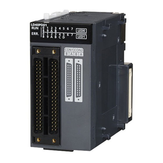
Page 23: Chapter 2 Part Names
PART NAMES This chapter lists the part names of the flexible high-speed I/O control module. Name Description Module joint lever A lever for connecting two modules RUN LED This LED indicates the operating status. On: Normal operation Flashing: During simulation Off: When 5V power off or a watchdog timer error has occurred ERR. - Page 24 MEMO 2 PART NAMES...
-
Page 25: Chapter 3 Specifications
SPECIFICATIONS This chapter describes general specifications, performance specifications, functions, I/O signals, and buffer memory areas. General Specifications For the general specifications of the flexible high-speed I/O control module, refer to the following. Safety Guidelines, provided with the CPU module or head module 3 SPECIFICATIONS 3.1 General Specifications... -
Page 26: Performance Specifications
Performance Specifications The following table lists the performance specifications of the flexible high-speed I/O control module. Item Specifications Differential Number of input points 12 points (common for 5VDC/24VDC/differential) Number of output points 6 points 8 points (5 to 24VDC, 0.1A/point) Number of interrupts 8 points Input response time... - Page 27 Item Specifications Differential Main functions Pulse count Count input Phase 1-phase input (1 multiple/2 multiples), 2-phase input (1 multiple/2 multiples/4 that can be signal multiples), CW/CCW performed with Counting 1 multiple 10kpps/100kpps/200kpps/ 500kpps/ 10kpps/100kpps/200kpps the combination speed 1Mpps/2Mpps of main blocks 2 multiples 10kpps/100kpps/200kpps/500kpps/ 1Mpps/2Mpps/4Mpps...
- Page 28 Item Specifications Differential Number of occupied modules External dimensions Height 90mm Width 45mm Depth 95mm Weight 0.18kg *1 The basic blocks supplied by the configuration tool 3 SPECIFICATIONS 3.2 Performance Specifications...
-
Page 29: Number Of Parameter Settings
Number of parameter settings Set the parameters of the auto refresh setting for the flexible high-speed I/O control module so that the number of the set parameters including the number of the parameters for other intelligent function modules will not exceed the maximum number of parameters that can be set for the CPU module. -
Page 30: Function List
Function List The following table lists the functions of the flexible high-speed I/O control module. Item Description Reference Page 103 CREATING A Hardware logic control function Users can create the hardware logic to perform a desired control with the configuration tool. HARDWARE LOGIC Page 58 Error History Error history function... -
Page 31: List Of I/O Signals
List of I/O Signals The following table lists the I/O signals of the flexible high-speed I/O control module to the CPU module. For details on the I/O signals, refer to the following. Page 240 Details of I/O Signals Input (Signal direction: CPU module ← Flexible high-speed I/O Output (Signal direction: CPU module →... -
Page 32: List Of Buffer Memory Addresses
List of Buffer Memory Addresses The following table lists the buffer memory addresses of the flexible high-speed I/O control module. For details on the buffer memory areas, refer to the following. Page 247 Details of Buffer Memory Areas Do not write any data to the system area and write-protect area of the buffer memory. If data is written to these areas, a malfunction may occur. - Page 33 Address Address Name Default value Read/write (decimal) (hexadecimal) 8105 to 8109 1FA9H to 1FADH System area 8110 to 8114 1FAEH to 1FB2H Error history No. 11 Same with error history No. 1 8115 to 8119 1FB3H to 1FB7H System area 8120 to 8124 1FB8H to 1FBCH...
-
Page 34: Chapter 4 Procedures Before Operation
PROCEDURES BEFORE OPERATION This chapter describes the procedures before operation. Installing the module Install the flexible high-speed I/O control module with a desired configuration. Page 34 Overall Configuration External wiring Wire external devices to the flexible high-speed I/O control module. Page 37 External Wiring Creating a hardware logic Create a hardware logic with the configuration tool. - Page 35 MEMO 4 PROCEDURES BEFORE OPERATION...
-
Page 36: Chapter 5 System Configuration
SYSTEM CONFIGURATION This chapter describes the overall system configuration, number of connectable modules, and compatible software versions of the flexible high-speed I/O control module. Overall Configuration The following figure shows a system configuration example of when the flexible high-speed I/O control module is used. When connected to the CPU module Display unit (optional) -
Page 37: Applicable System
Applicable System Number of connectable modules For the number of connectable modules, refer to the following. MELSEC-L CPU Module User's Manual (Hardware Design, Maintenance and Inspection) MELSEC-L CC-Link IE Field Network Head Module User's Manual Compatible software version The following table lists compatible software versions. -
Page 38: Chapter 6 Installation And External Wiring
INSTALLATION AND EXTERNAL WIRING This chapter describes the installation and external wiring of the flexible high-speed I/O control module. Installation Environment and Installation Position For precautions for the installation environment and installation position, refer to the following. MELSEC-L CPU Module User's Manual (Hardware Design, Maintenance and Inspection) ... -
Page 39: External Wiring
External Wiring This section describes wiring of encoders and controllers to the flexible high-speed I/O control module. External wiring precautions To obtain the maximum performance from the functions of the flexible high-speed I/O control module and improve the system reliability, an external wiring with high durability against noise is required. This section describes the precautions for wiring of encoders and controllers. - Page 40 Measures to reduce noise The flexible high-speed I/O control module may malfunction if pulse-like noise is input. Thus, take the following measures to reduce noise: • Always use a shielded twisted pair cable. • Arrange a shielded twisted pair cable keeping a distance of 150mm or more from the power cable, I/O cables, or other cables that cause much noise.
- Page 41 Compliance with the EMC and Low Voltage Directives Take the following measures for compliance with the EMC and Low Voltage Directives. • Always attach a ferrite core on the DC power supply cable to be connected to the flexible high-speed I/O control module and the one to be connected to a controller.
- Page 42 ■Example of noise reduction measures taken to shielded cables (1), (3) Remove the jacket of each shielded cable. Take out a shield from a shielded cable and solder it on the FG wire. Connect a shield of each shielded cable with a conductive tape. Cover a connector pin with a heat-shrinkable insulation tube to protect signal wires.
-
Page 43: Connector For External Devices
Connector for external devices Precautions • Tighten the connector screws within the specified tightening torque range. Screw Tightening torque range Connector screw (M2.6) 0.20 to 0.29N⋅m • Use copper wires having temperature rating of 75 or more for the connectors. •... - Page 44 Connection procedure Plug the connector into a slot on the flexible high-speed I/O control module. Connector screw Tighten the two connector screws (M2.6). Removal procedure Loosen the two connector screws and pull out the connector from the module. 6 INSTALLATION AND EXTERNAL WIRING 6.2 External Wiring...
-
Page 45: Interface With External Devices
Interface with external devices The following table shows the interface of the flexible high-speed I/O control module with external devices. Electrical specifications of external I/O signals ■External input signal The following table shows the input specifications of the flexible high-speed I/O control module. Signal name Operation Input voltage... - Page 46 Signal layout of a connector for external devices The following shows the signal layout of a connector for external devices of the flexible high-speed I/O control module. CON1/CON2 Pin No. CON1 CON2 IN 0_24V IN 0_5V IN 6_24V IN 6_5V IN 0_DIF IN 0_COM IN 6_DIF...
- Page 47 ■List of input signals The following table lists the input signals of the flexible high-speed I/O control module. Pin No. CON1 CON2 Description Symbol Signal name Symbol Signal name Empty pin IN 0_24V High-speed input 0 IN 6_24V High-speed input 6 Inputs the + (plus) side.
- Page 48 ■List of output signals The following table lists the output signals of the flexible high-speed I/O control module. Pin No. CON1 CON2 Description Symbol Signal name Symbol Signal name OUT 0 High-speed output 0 OUT 4 High-speed output 4 5 to 24VDC output OUT 1 High-speed output 1 OUT 5...
- Page 49 Internal circuit of the interface for external devices The following table lists the internal circuits of the interface for external devices of the flexible high-speed I/O control module. Internal circuit Connector Signal name classification CON1 CON2 CON1 CON2 Input High-speed input 0 High-speed input 6 IN 0_DIF(B18) 24VDC...
- Page 50 Internal circuit Connector Signal name classification CON1 CON2 CON1 CON2 Input High-speed input 5 High-speed input B IN 5_DIF(B8) 24VDC 24VDC IN B_DIF(B8) High-speed input 5 High-speed input B 5VDC 5VDC IN 5_5V(A9) IN B_5V(A9) High-speed input 5 High-speed input B differential differential IN 5_24V(B9)
- Page 51 ■Input signal status in the hardware logic (High/Low) The input signal status (High/Low) in the hardware logic is determined depending on the input signals (ON/OFF) from external devices and logical selection. Logic selection External wiring High/Low state of the external input signal IN 0 observed from the flexible high-speed I/O control module Not inverted When a voltage is not applied (OFF)
-
Page 52: Connectable Encoders
Connectable encoders The following tables list encoders that can be connected to the flexible high-speed I/O control module. • Encoders with the following counting methods Counting method Condition Incremental method Absolute method Encoders with the following specifications can be connected. •... -
Page 53: Examples Of Wiring Between A Controller And External Input Terminals
Examples of Wiring Between a Controller and External Input Terminals This section shows examples of wiring between a controller and external input terminals. Example of external wiring with a controller (Sync load type) Flexible high-speed I/O control module Shielded twisted pair cable Controller A IN 0_DIF... -
Page 54: Example Of External Wiring Between The Flexible High-Speed I/O Control Module And An Encoder
Example of External Wiring Between the Flexible High-speed I/O Control Module and an Encoder This section shows an example of external wiring between the flexible high-speed I/O control module and an encoder. Example of external wiring with an open collector output type encoder (24VDC) Flexible high-speed I/O control module IN 0_DIF... - Page 55 • For the wiring between the flexible high-speed I/O control module and an encoder, separate the power supply cables and signal wires. Flexible high-speed I/O control module Pulse input +24V Shielded twisted pair cable Encoder External 24VDC power supply • Do not wire the module and an encoder as shown in the figure below. Because a current flows through a shielded twisted pair cable in a single direction and the canceling effect disappears, the module is easy to be affected by electromagnetic induction.
-
Page 56: Example Of External Wiring With A Line Driver (Equivalent To Am26Ls31) Encoder
Example of external wiring with a line driver (equivalent to AM26LS31) encoder Flexible high-speed I/O control module IN 0_DIF IN 0 IN 0_5V (Phase A input) IN 0_24V 240Ω 270Ω 4.1kΩ 820Ω Encoder IN 0_COM Shielded twisted pair cable IN 1_DIF Phase A IN 1 input... -
Page 57: Example Of External Wiring With The Ssi Encoder (Serial Communication)
Example of external wiring with the SSI encoder (serial communication) Connect the flexible high-speed I/O control module to the SSI encoder using a shielded twisted pair cable of 0.2mm thicker (24 AWG or larger). Make sure to check the SSI encoder specifications. In addition, separately prepare an external power supply for the SSI encoder. -
Page 58: Example Of External Wiring With External Output Terminals
Example of External Wiring with External Output Terminals This section shows an example of external wiring with external output terminals. Example of external wiring with output terminals (Sink output type) Flexible high-speed I/O control module OUT 0 Digital isolator Load OUT 4 IO 5V 680Ω... -
Page 59: Example Of External Wiring With Differential Receivers (Differential Output Type)
Example of external wiring with differential receivers (Differential output type) Flexible high-speed I/O control module Digital isolator Controller OUT 0_DIF+ OUT 3_DIF+ IO 5V OUT 0_DIF- OUT 3_DIF- OUT 1_DIF+ OUT 4_DIF+ OUT 1_DIF- OUT 4_DIF- OUT 2_DIF+ OUT 5_DIF+ OUT 2_DIF- OUT 5_DIF- OUT_DIF_GND... -
Page 60: Chapter 7 Functions
FUNCTIONS This chapter describes the details on the functions that can be used in the flexible high-speed I/O control module and their setting methods. Hardware Logic Control Function Users can create the hardware logic to perform a desired control with the configuration tool. For details, refer to the following. - Page 61 Checking the error history The start address of the error history where the latest error has been stored can be checked with Latest address of error history (Un\G8000). The following shows the case in which the third error has occurred. The third error is stored in Error history No. 3 and 8030 (start address of Error history No.3) is stored in Latest address of error history (Un\G8000).
- Page 62 The following shows the case in which the 17th error has occurred. The 17th error is stored in Error history No. 1 and 8010 (start address of Error history No. 1) is overwritten to Latest address of error history (Un\G8000). Latest address of error history (Un\G8000) Address...
-
Page 63: Module Error Collection Function
Module Error Collection Function The errors that occurred in the flexible high-speed I/O control module are collected in the CPU module. To hold errors even after the power is turned off or the CPU module is reset, save the errors in the memory that can hold data during power failure in the CPU module. -
Page 64: Error Clear Function
Error Clear Function When an error has occurred, the error can be cleared from "System Monitor". Clicking the [Error Clear] button in "System Monitor" clears the latest error code stored in Latest error code (Un\G100) and turns off the ERR. LED. This action is the same action as the one to be taken when errors are cleared with Error clear request (YF) or the display unit. -
Page 65: Chapter 8 Functions Of The Configuration Tool
FUNCTIONS OF THE CONFIGURATION TOOL This chapter describes the configuration tool for creating the hardware logic and writing it into the flexible high-speed I/O control module. For how to get the configuration tool, refer to the following. Page 251 How to Get the Configuration Tool How to Install and Uninstall the Configuration Tool For the procedures of installing and uninstalling the configuration tool, refer to the following. -
Page 66: Starting And Exiting The Configuration Tool
Starting and Exiting the Configuration Tool This section describes how to start and exit the configuration tool. Start Before starting the configuration tool, add the module with GX Works2. The following describes the operation method. Add the flexible high-speed I/O control module on GX Works2. [Project window] of GX Works2 ... - Page 67 ■Connection target Setting the I/O assignment to GX Works2 and the configuration tool enables writing of data into the flexible high-speed I/O control module and the monitor display through the CPU module. However, do not change the I/O assignment on GX Works2 after the configuration tool is started. If the I/O assignment is changed on GX Works2 and data writing to the module, the monitor display, or simulation is executed after the configuration tool has been started, a communication error will occur.
-
Page 68: Switching The Language
Switching the Language The configuration tool supports multiple languages. Users can switch the language to be displayed in the menu on a personal computer. How to switch the language [View] [Switching display language] When a selected language is different from the one set to the OS, character strings may not be properly displayed. -
Page 69: Window Layout
Window Layout The following figure shows the whole window layout. Title bar Menu bar Toolbar Element selection window Navigation window Work window Status bar Map display window For details on each item, refer to the following. Page 67 Navigation window Page 69 Work window Page 68 Element Selection window Page 70 Map display window... -
Page 70: Element Selection Window
Element Selection window In the Element Selection window, the main blocks that can be arranged when the hardware logic is created are displayed in the tree format. This window displays only the blocks in a category selected from the drop-down menu at the upper section of the window. When a multi function counter block is selected in the Element Selection window and arranged on the work window, the tab of the block is added in the work window. -
Page 71: Work Window
Work window The hardware logic is created or the monitor display is executed in the work window. One of the hardware logic outline window (one window) and multi function counter block detail windows (up to eight windows) is displayed. Switch the window with one of the following operations. •... -
Page 72: Map Display Window
Map display window The map display window displays the hardware logic outline window that is currently being displayed or a whole image of multi function counter block detail windows in the work window. Click the area to display to move the display position of the work window. 8 FUNCTIONS OF THE CONFIGURATION TOOL 8.4 Window Layout... -
Page 73: List Of Menus Of The Configuration Tool
List of Menus of the Configuration Tool [Project] menu Menu Reference [Project] [New] Page 72 Creating a new project Page 72 Opening a project [Project] [Open] Page 73 Saving an existing project [Project] [Save] Page 73 Saving a project with a new name [Project] ... -
Page 74: Project Management
Project Management The configuration tool manages the hardware logic as a project. This section describes the basic operations of the configuration tool for projects, such as creating, opening, and saving of a project. Because a created project can be managed as a project file, changing of a project name, copying and pasting of a project, ... -
Page 75: Saving A Project File
Saving a project file Save a project file in a hard disk or other areas in a personal computer. Saving a project with a new name Name the project being edited and save the project file. [Project] [Save As] Saving an existing project Overwrite the hardware logic information being edited on an existing project file. -
Page 76: Security
Security When the hardware logic is written into a flash ROM, add a password to prevent inappropriate access to read the data. After the security is set to "Enable" and [Write to Module (execution + flash ROM)] in [Online] is executed, the password input window is displayed. - Page 77 ■Actions to be taken when "Read from Module (flash ROM)" is executed Hardware logic in the Description module With a password • The password input window is displayed. • Only when the input password matches the password in the module, the hardware logic can be read. Without a password •...
-
Page 78: Windows For Creating The Hardware Logic
Windows for Creating the Hardware Logic The following two types of window are prepared for creating the hardware logic. The window can be switched between the hardware logic outline window and the multi function counter block detail window. Window Description Hardware logic outline window This window is for creating the outline of the hardware logic in the flexible high-speed I/O control module. -
Page 79: Hardware Logic Outline Window
Hardware logic outline window The hardware logic outline window is composed of the following five sections. Depending on the section, the blocks that can be arranged differ. Change the setting and wiring of each block to create the hardware logic with various functions. Section Description Blocks and terminals... -
Page 80: Multi Function Counter Block Detail Window
Multi function counter block detail window A multi function counter block detail window is composed of the following six sections. Change the setting and wiring of each block to create various count operations. Section Description Block and terminals that have been arranged First section The terminals corresponding to inputs to a multi function counter block have been... -
Page 81: How To Use Blocks
How to use blocks Arranging blocks The following describes how to arrange a block. Select a block in the Element Selection window. Drag and drop the block into the hardware logic outline window. When a block is dragged into the hardware logic outline window, the area to which the block can be dropped is highlighted. When the selected block is dropped into the work window, the block is automatically arranged in the highlighted area. - Page 82 Block setting Configure block settings by changing values in the drop-down lists and text boxes of each block. Item name Description Drop-down list Select a setting value from the drop-down list. Text box Input a one-byte numerical value (decimal). User Address •...
- Page 83 Linking blocks Link blocks so that an output terminal of the left block in the window is handled as a start point and the input terminal of the right block in the window is handled as an end point. The following describes how to link blocks. Click the terminal to be a start point.
- Page 84 ■Linking conditions of terminals Terminals in the same color can be linked. Terminals with two colors can be linked with the terminals with either of the two colors. For details on the terminal colors, refer to the following. Page 103 Main Blocks in the Hardware Logic Outline Window ■Link type The two link colors, blue and gray, are provided.
- Page 85 Copying a block A block arranged in the hardware logic outline window can be copied by block unit. The setting values can be changed by block in a batch and an arranged block can be copied. ■Procedure of copying a block The following describes the procedure of copying a block.
- Page 86 Pasting a block This function pastes the copy of a block. Select [Edit] [Paste] for a block with the same type as the copy to overwrite the setting values with the ones of the copy at a time. Select [Edit] [Insert and Paste] to add the copy as a new block in the hardware logic outline window.
-
Page 87: Library Function
Library Function A library is a block in which the types and setting values of main blocks have been combined. Libraries can be shared between multiple projects by registering them in the configuration tool. There are the following two types of library. Library type Description Library provided by the manufacturer... - Page 88 Operation details and restrictions • Multiple blocks cannot be exported at a time. Only a single block can be exported. • The link between the block to be exported and other blocks is not exported. However, when the block to be exported is a multi function counter, the link information in the multi function counter block detail window and the link between Event terminals of a multi function counter block in the hardware logic outline window are also exported.
-
Page 89: Library Operation
Library operation The following describes the library. No library exists immediately after the installation of the configuration tool. Register libraries as necessary. Registering a library Register the libraries provided by the manufacturer and exported user libraries in the configuration tool. Registering libraries adds the blocks in library files in the "Library"... -
Page 90: Online Functions
Online Functions Connect the computer in which the configuration tool has been installed and the CPU module, and read or write data from/to the flexible high-speed I/O control module through the CPU module. The following table lists the online functions. Function Description Reference... -
Page 91: Writing Data To The Module
Writing data to the module Write the hardware logic to the execution memory of the flexible high-speed I/O control module. The execution memory and the flash ROM can be selected as the write destination of the data. Select only the execution memory or both the execution memory and the flash ROM as the write destination. -
Page 92: Reading Data From The Module
Reading data from the module Read the hardware logic saved in the flash ROM of the flexible high-speed I/O control module to the configuration tool. The hardware logic being edited is overwritten by the read data. Save the hardware logic before the data reading as necessary. -
Page 93: Verifying With The Module
Verifying with the module Verify the hardware logic in the project file being edited and the hardware logic saved in the flash ROM of the flexible high- speed I/O control module. Verification results are displayed in a list and mismatches can be checked. Verifying the hardware logic The following describes how to verify the hardware logic. -
Page 94: Module Operation
Module operation The hardware logic control can be started or stopped with the configuration tool. Start or stop the hardware logic control under the following situations. Operation Situation Starting the hardware logic control • Use this operation after the power is turned on. The hardware logic control is stopped after the power-on. Check the safety and select [Hardware logic control start] to start the control. -
Page 95: Monitor
Monitor The High/Low states of I/O terminals and count values are displayed in the hardware logic outline window or a multi function counter block detail window. The following lists the items that can be monitored. Window Block Item Hardware logic outline window External input block ON/OFF state of the corresponding external input terminal High/Low state of the output terminal... - Page 96 Monitor display ■Monitor display target The following terminals can be monitored. Monitor values of the terminals that have not been linked are not displayed. Window name Block name Terminal Item to be monitored Hardware logic outline External input block IN 0 to IN B ON/OFF state of the input window...
-
Page 97: Debug Function
8.10 Debug Function Simulation can be executed as the debug function. Simulation function The simulation function verifies the hardware logic written into the flexible high-speed I/O control module without wiring with external devices. With the configuration tool, create "simulation input data", the substitute for external input signals, and write the data into the flexible high-speed I/O control module to operate the hardware logic. - Page 98 The following table lists the items to be displayed in the "Simulation Settings" window. Item Description External input signal data setting area To verify the hardware logic, set the status of data to be imported as external input signals (IN 0 to IN B). The setting value 0 indicates that an external input signal is off, and the setting value 1 indicates that an external input signal is on.
- Page 99 How to use The following describes how to use the simulation function. Open the "Simulation Settings" window. [Debug] [Simulation] Click each cell in the external input signal data setting area and switch "0: External input signal OFF" and "1: External input signal ON".
- Page 100 Set "Simulation step unit time setting". Changing "Simulation step unit time setting" changes the following timing. • Timing to move external input data to the next step (Data is changed one step by one step at the set unit time.) •...
- Page 101 Click "Writing to Module" to write the simulation input data into the flexible high-speed I/O control module. If a communication error has occurred during the communication with the module with the simulation function, the possible cause is one of the following causes. Check the target module and communication status. •...
- Page 102 CSV file format of simulation execution results The following shows the CSV format specifications of simulation execution results. Item name Character Delimiter Comma (,) Return code CRLF (0x0D, 0x0A) ■1st row [LOGGING], LD40PD01_1, 2, 3, and 4 are output (fixed output). ■2nd row The data type of the simulation execution result is output.
- Page 103 The data in the 0th step of the simulation input data is reflected to the initial value of the Output terminal in the external input block. Because the processing time of the hardware logic affects the simulation step, the following time is required until the simulation input data changes the Output terminal in the external input block.
-
Page 104: Help Function
8.11 Help Function As the help function, the software version of the configuration tool can be checked. Checking the version of the configuration tool Information including the software version of the configuration tool is displayed. [Help] [Version Information] 8 FUNCTIONS OF THE CONFIGURATION TOOL 8.11 Help Function... -
Page 105: Chapter 9 Creating A Hardware Logic
CREATING A HARDWARE LOGIC This chapter describes how to create a hardware logic. Main Blocks in the Hardware Logic Outline Window With the flexible high-speed I/O control module, various controls are possible by arranging multi function counter blocks and various function blocks and linking these blocks. In the hardware logic outline window, all of external input blocks, Y device terminals, and OUT terminals are arranged in the first section and all of external output blocks and SI device terminals are arranged in the fifth section when a project is stated. - Page 106 Relationship of I/O in the hardware logic This section describes the relationship between the I/O in the hardware logic and the I/O of X/Y devices and of the connectors for external devices. CPU module Flexible high-speed I/O control module Program Hardware logic Connector for Connector for...
- Page 107 Link combination The terminals to which the terminals of each main block can be linked are predetermined. An input terminal and an output terminal in the same color can be linked. Input terminals or output terminals cannot be linked each other. The following table lists the combinations.
-
Page 108: External Input Block
External input block Outline In the first section in the hardware logic outline window, 12 external input blocks ("IN 0" to "IN B") are arranged by default. Select which signal (among "IN 0" to "IN B") input from the connector for external devices is to be used as an input signal in the hardware logic. - Page 109 ■"Filter Time" General-purpose input or pulse input count can be selected for "Filter Time". • General-purpose input (General Input 0μs to General Input 5ms) Set this method to reduce noise. When a pulse width is less than the setting value of "Filter Time", the pulse is not detected as an input signal.
- Page 110 ■Minimum value of the pulse width that may be taken in as input For general-purpose input, noise or others may be taken in as input depending on the filter time setting. The following table lists the minimum values of the pulse width that may be taken in as input for each filter time. Filter time Minimum value of the pulse width that may be taken in as input 10μs...
-
Page 111: Y Device Terminal
Y device terminal Outline In the first section in the hardware logic outline window, 16 Y device terminals ("Y 10" to "Y 1F") are arranged by default. The ON/OFF states of General command 0 to General command F (Y10 to Y1F) are output as signals and used as inputs in the hardware logic. -
Page 112: Out Terminal
OUT terminal Outline In the first section in the hardware logic outline window, eight OUT terminals for DC output ("OUT 0" to "OUT 7") and six OUT terminals for differential output ("OUT 0_DIF" to "OUT 5_DIF") are arranged by default. Signals output from external output blocks in the fifth section can be used as inputs in the hardware logic. -
Page 113: Parallel Encoder Block
Parallel encoder block Outline In the second section in the hardware logic outline window, one parallel encoder block ("Parallel_Encoder") can be arranged. The parallel encoder block transmits data with the encoder for parallel transmission and receives the data of the bit points set in the data length setting as the data of Input Data Type to convert this data into word data. - Page 114 Parameter The following table shows the parameters of the parallel encoder block. Variable name Data type Valid range Default value Description Input Data Type Word Pure binary Pure binary Set the input data type of the parallel interface. Gray code •...
- Page 115 ■Setting and link of the encoder for which Input Data Type is set to Pure binary or BCD When data is input from the encoder for which Input Data Type is set to Pure binary or BCD, an error of 2 bits or more is generated depending on the timing of reading data.
-
Page 116: Ssi Encoder Block
SSI encoder block Outline In the second section in the hardware logic outline window, two SSI encoder blocks (SSI_Encoder_) can be arranged. The SSI encoder blocks perform serial communication with the absolute encoder having the SSI (Synchronous Serial Interface) output and acquire position data. The acquired position data is stored as a count value of the multi function counter block linked to this block. - Page 117 Parameter The following table shows the parameters of the SSI encoder block. Variable name Data type Valid range Default value Description Encoder Type Word Single Turn Single Turn Set the type of the SSI encoder. Multi Turn • Single Turn •...
- Page 118 • Parameters of "Data Frame Setting" Variable name Data type Valid range Default value Description Input Data Type Word Pure binary Pure binary Set the type of input data from the SSI encoder. Gray code • Pure binary • Gray code Data Frame Length Word 1 to 32 (bit)
- Page 119 Output The following table shows the outputs of the SSI encoder block. Variable name Data type Linkable block Output value Description Clock External output 0, 1 Outputs the clock signal to perform synchronous data communication with the SSI encoder. When an SSI encoder block is arranged in the hardware logic outline window, the "Clock"...
- Page 120 Setting examples of the SSI encoder block This section shows setting examples of the SSI encoder block suitable for a receive frame from the SSI encoder and communication specifications. ■Multi turn The following example is for the receive frame of a multi turn encoder. The receive frame consists of the elements below. •...
- Page 121 ■Single turn The following example is for the receive frame of a single turn encoder. The receive frame consists of the elements below. • Single turn: 24 bits • Status bit: 1 bit • Parity bit: None Clock Most significant bit Least significant bit Receive frame bit position...
- Page 122 Monoflop time The monoflop time indicates the time set aside to refresh position data of the SSI encoder. The time is stipulated by an encoder type. If the monoflop time is set to be shorter than the stipulated time, correct position data cannot be received. When CLK transmission from the connected device is stopped by the monoflop time, the DATA signal from the SSI encoder returns to High.
- Page 123 Receive data monitor Out of the data frame received from the SSI encoder, the information for the number of bits specified with "Data Frame Length" is stored in the following buffer memory areas. (The parity bit is not included.) Buffer memory address SSI encoder block Un\G110, Un\G111 SSI_Encoder_0...
-
Page 124: Logical Operation Block
Logical operation block Outline In the fourth section in the hardware logic outline window, 14 logical operation blocks ("Logic_Operation_0" to "Logic_Operation_D") can be arranged. Any logical operation of AND operation, OR operation, or XOR operation is executed for all signals input to the "Input" terminal. -
Page 125: External Output Block
External output block Outline In the fifth section in the hardware logic outline window, eight external output blocks for DC output ("OUT 0" to "OUT 7") and six external output blocks for differential output ("OUT 0_DIF" to "OUT 5_DIF") are arranged by default. The result of the operation from the first to the fourth section in the hardware logic is output from the connector for external devices (OUT 0 to OUT 7, OUT 0_DIF to OUT 5_DIF). - Page 126 Parameter The following table shows the parameters of the external output block. Variable name Data type Valid range Default value Description Logic Select Non-Inversion Non-Inversion Set Non-Inversion or Inversion for input signals. Inversion Delay Time (Step) Word 0 to 64 Adjust the signal output timing.
- Page 127 ■Delay time A delay time is calculated by multiplying "Delay Time(Unit)" by "Delay Time(Step)". An error of one unit time may be generated in delay time. However, the error can be reduced by setting the delay time as shown below. •...
-
Page 128: Si Device Terminal
SI device terminal Outline In the fifth section in the hardware logic outline window, eight SI device terminals ("SI 0" to "SI 7") are arranged by default. When a signal is input to an SI device terminal, an interrupt request is output to the CPU module to start an interrupt program. The interrupt program corresponding to each SI device terminal needs to be set in GX Works2 in advance. -
Page 129: Multi Function Counter Block
Multi Function Counter Block Outline In the third section in the hardware logic outline window, up to eight multi function counter blocks ("Counter_0" to "Counter_7") can be arranged. Set details on how to count pulses of input signals in a multi function counter block detail window. To shift to a multi function counter block detail window, double-click the corresponding block in the hardware logic outline window. - Page 130 Name Block diagram Specifications Available Number of Number of Availability count value Latch Event of "Cam terminals terminals Output" terminal Counter_(32bit_Unsigned) 32-bit (32-bit unsigned multi unsigned function counter block) value Input The following table shows the inputs of the multi function counter block. Variable name Data type Linkable block...
- Page 131 Output The following table shows the outputs of the multi function counter block. Variable name Data type Linkable block Output value Description Output 0 • External output 0, 1 The output terminal is for external output signals and • SI device interruption.
-
Page 132: Internal Blocks Of Multi Function Counter Blocks
Internal blocks of multi function counter blocks There are 12 types of internal blocks in a multi function counter block. Control operations can be freely customized by linking the internal blocks. When a multi function counter block is arranged in the hardware logic outline window, all internal blocks are arranged in the multi function counter block detail window. - Page 133 Link combination An input terminal and output terminal in the same color can be linked among the internal blocks. Input terminals or output terminals cannot be linked each other. The following table lists the combinations. Output side Input side Color Block name Terminal name Block name...
- Page 134 ■Restrictions on linking the same-color terminals for 16-bit multi function counter blocks For 16-bit multi function counter blocks, linkable combinations of blocks and terminals are restricted even if the terminals are in the same color. • Input signal event detection block and event output terminal Input signal event detection block (output side) Event output terminal (input side) Block name...
- Page 135 Assignment of "User Address" "User Address" can be set to particular internal blocks arranged in a multi function counter block detail window. By assigning buffer memory addresses to "User Address", the status of input terminals and parameter setting values can be changed with programs and values of the hardware logic can be monitored during the hardware logic control.
-
Page 136: Input Terminal
Input terminal Multi function In the first section in a multi function counter block detail window, two input terminals ("Input 0", "Input 1") are arranged by default. They are used to use signals input to a multi function counter block in the hardware logic outline window ("Input 0", "Input 1") as input signals in the multi function counter block detail window. -
Page 137: Event Input Terminal
Event input terminal Multi function In the first section in a multi function counter block detail window, event input terminals are arranged by default. For a 16-bit counter, four event input terminals ("Event 0" to "Event 3") are arranged. For a 32-bit counter, two event input terminals ("Event 0", "Event 1") are arranged. -
Page 138: Input Signal Event Detection Block
Input signal event detection block Multi function In the second section in a multi function counter block detail window, one input signal event detection block ("Input_Signal_Event") is arranged by default. Set conditions to detect input signals of a multi function counter block. When the detection conditions are satisfied, the Output terminal turns to High. - Page 139 Parameter The following tables show the parameters of the input signal event detection block. • Parameter of "Detector Select" Variable name Data type Valid range Default value Description Detector Select Word Set the condition to detect signals. Click the [Detector Select] button to open the detection condition setting window ("Select Box").
- Page 140 Variable name Data type Valid range Default value Description B: Fall When the fall of "Input B" has been detected, Output turns to High only for one clock cycle. The status of "Input A" does not affect the status of Output. Input A Input B Output...
- Page 141 Variable name Data type Valid range Default value Description A: Low+B: Rise When the Low state of "Input A" and the rise of "Input B" have been detected, Output turns to High only for one clock cycle. Input A Input B Output A: High+B: Rise When the High state of "Input A"...
- Page 142 ■Pulse input modes and count timing The following table shows the relationships between each pulse input mode and count timing. "Pulse Input Mode" Count timing The value is counted up at the rise (↑) of ΦA. 1-phase multiple of 1 (1-Phase Multiple of 1+, 1- At up count ΦA Phase Multiple of 1-)
- Page 143 ■Detection conditions in pulse input modes The following table shows the detection conditions in each pulse input mode. Pulse input mode "Pulse Input Detection condition Mode" 1-phase 1-Phase Multiple of 1+ ...
- Page 144 Output The following table shows the outputs of the input signal event detection block. Variable name Data type Linkable block Output value Description Output 0 • Counter timer 0, 1 Outputs signals detected with the detector. • Set/reset Output 1 •...
-
Page 145: Latch Event Detection Block
Latch event detection block Multi function In the second section in a multi function counter block detail window, one latch event detection block ("Latch_Event") is arranged by default. Set conditions to detect latch input signals of the multi function counter block. When the detection conditions are satisfied, the Output terminal turns to High. - Page 146 Parameter The following tables show the parameters of the latch event detection block. • Parameter of "Detector Select" Variable name Data type Valid range Default value Description Detector Select Word Set the condition to detect signals. Click the [Detector Select] button to open the "Select Box"...
-
Page 147: Counter Timer Block
Counter timer block Multi function In the third section in a multi function counter block detail window, counter timer blocks are arranged by default. For a 16-bit counter timer block, two counter timer blocks ("Counter_Timer_0"(16bit_Unsigned/Signed), "Counter_Timer_1"(16bit_Unsigned/Signed)) are arranged. For a 32-bit counter timer block, one counter timer block ("Counter_Timer_0"(32bit_Unsigned/Signed)) is arranged. - Page 148 • 32-bit multi function counter block The counter timer block has the following functions. • Input pulses are counted. • Input pulses are counted per clock cycle. • Either of the ring counter mode or the linear counter mode can be selected (For 16-bit counter timer blocks, only the ring counter mode can be selected).
- Page 149 Input The following table shows the inputs of the counter timer block. Variable name Data type Linkable block Valid range Description *1*6 • Event input 0, 1 Adds 1 to the count value per preset clock cycle. • Input signal event Multiple signals can be input to the terminal.
- Page 150 The High/Low states of the input terminals are detected per clock cycle. When the High states of multiple terminals are detected, only the input of the terminal with the highest priority becomes valid. The inputs of terminals with lower priority become invalid. Link the terminals so that multiple signals are not input at the same time.
- Page 151 Parameter The following table shows the parameters of the counter timer block. Variable name Data type Valid range Default value Description Count Enable Set the count enable to valid or invalid. OFF: Invalid ON: Valid Count Mode Linear Linear Set the counter mode to the ring counter or Ring the linear counter.
- Page 152 The settings of "Clock" of two 16-bit counter timer blocks must be the same. When one "Clock" setting is changed, the other "Clock" setting is changed automatically. The following table shows "User Address" used for the parameters. Variable name Data type Valid range Setting range Description...
- Page 153 Monitor The following table shows the monitors of the counter timer block. Variable name Data type Description Count Value Word A count value is stored in the buffer memory area specified with "User Address". Latch Value Word A latched count value is stored in the buffer memory area specified with "User Address". Overflow Word When an overflow is detected, 1 is stored in the buffer memory address specified with "User Address".
- Page 154 Counting method In the flexible high-speed I/O control module, the following counting methods are provided: counting addition pulses and subtraction pulses from external devices and performing up count per clock cycle. The counting method can be set by linking blocks in the hardware logic. Counting method Link in hardware logic Counting the input pulses from external devices...
- Page 155 Linear counter mode When the linear counter mode is selected, the count operation is performed between the lower limit value and the upper limit value. The following table shows the setting ranges (lower limit value and upper limit value). Multi function counter block Setting range 32-bit unsigned 0 to 4294967295...
- Page 156 ■Overflow/underflow error • In a 32-bit counter timer block with the linear counter mode setting, when "Count Value" exceeds the upper limit value in up count, the overflow error (error code: 100H) is stored in Latest error code (Un\G100). When "Count Value" falls below the lower limit value in down count, the underflow error (error code: 101H) is stored in Latest error code (Un\G100).
- Page 157 Ring counter mode When the ring counter mode is selected, the count operation is performed between "Lower Limit" and "Upper Limit" repeatedly. The overflow error and underflow error do not occur. Count value Upper limit value Counting down Counting up Lower limit value ■Lower limit value ≤...
- Page 158 ■Upper limit value ≤ Lower limit value When "Count Value" has reached the value of "Upper Limit" -1, "Lower Limit" is stored in "Count Value" in the next up count. When "Count Value" has reached the "Lower Limit", the value of "Upper Limit" - 1 is stored in "Count Value" in the next down count.
- Page 159 Addition mode When "Add Mode" is set to "ON", the following operations are performed. • For the count in clock cycles, a value set as the addition value is added per clock cycle. • For counting input pulses, a value set with "Add Value" is added when an addition pulse is input and a value set with "Add Value"...
-
Page 160: Comparison Block
Comparison block Multi function In the fourth section in a multi function counter block detail window, comparison blocks are arranged by default. For a 16-bit counter, two comparison blocks ("Compare_0", "Compare_1") are arranged. For a 32-bit counter, one comparison block ("Compare_0") is arranged. - Page 161 Parameter The following table shows the parameters of the comparison block. Variable name Data type Valid range Default value Description Condition Word Coincidence Coincidence Specify a comparison method. Range • Coincidence • Range Compare Mode A Word (Blank) (Blank) Select a mode for comparing the count value and Compare Mode B the compare value.
- Page 162 Output The following table shows the output of the comparison block. ■When "Condition" is set to "Coincidence" Variable name Data type Linkable block Output value Description Input Value A • Set/reset 0, 1 Outputs the comparison result between "Count Value" and •...
-
Page 163: Cam Switch Block
Cam switch block Multi function In a multi function counter block detail window, one cam switch block ("Cam_Switch") linked to a counter timer block is arranged across the fourth and fifth sections. However, no cam switch block is arranged in a 16-bit multi function counter block. - Page 164 Parameter The following table shows the parameters of the cam switch block. Variable name Data type Valid range Default value Description Number of Step Word 1 to 16 Set the number of steps of the cam switch. A step indicates the point in which the Low state is switched to the High state or the High state is switched to the Low state.
- Page 165 Output The following table shows the output of the cam switch block. Variable name Data type Linkable block Output value Description Output Cam switch output 0, 1 Outputs signals created in the cam switch block. Only the "Cam Output" terminal can be linked to the "Output" terminal.
- Page 166 ■When the number of steps is set to 2 • Setting details Item Setting value Number of Step Lower Limit -2147483648 Lower Limit Output State Step No.0 1000 Step No.1 2000 Upper Limit 2147483647 *1 Set it in the counter timer block. *2 When "Low"...
-
Page 167: Set/Reset Block
Set/reset block Multi function In the fifth section in the multi function counter block detail window, set/reset blocks are arranged by default. For a 16-bit counter, two set/reset blocks ("Set/Reset_0" and "Set/Reset_1") are arranged. For a 32-bit counter, one set/reset block is arranged. -
Page 168: Output Terminal
Output terminal Multi function In the sixth section in the multi function counter block detail window, one output terminal ("Output 0") is arranged by default. When terminals have been linked to the output terminal, the signals input to the output terminal can be output from the "Output"... -
Page 169: Event Output Terminal
Event output terminal Multi function In the sixth section in a multi function counter block detail window, event output terminals are arranged by default. For a 16-bit counter timer block, four event output terminals ("Event 0" to "Event 3") are arranged. For a 32-bit counter timer block, two event output terminals ("Event 0", "Event 1") are arranged. -
Page 170: Cam Switch Output Terminal
Cam switch output terminal Multi function In the sixth section in a 32-bit multi function counter block detail window, one cam switch output terminal ("Cam Output") is arranged by default. No cam switch output terminal is arranged in a 16-bit multi function counter block. The arranged cam switch output terminal is linked with the cam switch block. -
Page 171: Intelligent Function Module Interrupt
Intelligent Function Module Interrupt This function outputs an interrupt request to the CPU module and starts an interrupt program when a signal is input to an SI device terminal. Operation When an input signal event is detected or a comparison condition is satisfied, a signal is input from the "Output" terminal of a multi function counter block to an SI device terminal. - Page 172 ■Setting the hardware logic The following figure shows link examples of the hardware logic. • Hardware logic outline window • Multi function counter block detail window (Counter_0(16bit_Unsigned)) 9 CREATING A HARDWARE LOGIC 9.3 Intelligent Function Module Interrupt...
- Page 173 • Multi function counter block detail window (Counter_1(32bit_Unsigned)) • Multi function counter block detail window (Counter_2(32bit_Unsigned)) • An SI device terminal linked in the hardware logic must be assigned to an interrupt pointer of the CPU module. If an unassigned SI device terminal turns to High, an error occurs in the CPU module. •...
-
Page 174: Chapter 10 Block Link Examples
BLOCK LINK EXAMPLES Various controls can be performed with the combinations of various blocks. This chapter shows link examples to perform the following controls. Control name Description Reference Page 173 Coincidence Coincidence detection Turns on the output of the multi function counter block at coincidence detection. Detection Page 178 One-shot Timer One-shot timer... -
Page 175: Coincidence Detection
10.1 Coincidence Detection The output of the multi function counter block is turned on when a count value matches with a compare value. The compare value is required to be set in advance as a coincidence detection value. The following describes a link and parameter example of coincidence detection. With the example setting, an external output signal turns on when the count value becomes 1000 and an interrupt request is sent to the CPU module. - Page 176 ■Multi function counter block detail window • Counter_0 (32bit_Unsigned) Block Variable name Setting value Description Input 0 Input 1 Input_Signal_Event Detector Select 2-Phase Multiple of 1+ Set this parameter to detect an addition pulse. Detector Select 2-Phase Multiple of 1- Set this parameter to detect a subtraction pulse.
- Page 177 • Counter_1 (32bit_Unsigned) Block Variable name Setting value Description Input 0 Input_Signal_Event Detector Select User Setting (ON only in A: Rise) Set "Only A: Rise is on". Detector Select This parameter is not used in this link example. Output ...
- Page 178 The multi function counter block with a link for coincidence detection can be used as a trigger of other multi function counter blocks. The following shows link examples of the hardware logic outline window and multi function counter block _0 detail window. •...
- Page 179 Precautions for using 16-bit multi function counter blocks Coincidence detection control can be set even with 16-bit multi function counter blocks. However, usable blocks are different. The following shows link examples of the hardware logic outline window and multi function counter block detail window. •...
-
Page 180: One-Shot Timer
10.2 One-shot Timer The output signal is turned on for the specified time period using an input signal as a trigger. The following describes a link and parameter example of a one-shot timer. With the example setting, an output is turned on for 100ms using an external input signal as a trigger. - Page 181 ■Multi function counter block detail window Block Variable name Setting value Description Input 0 Input_Signal_Event Detector Select User Setting (ON only in A: High) Set this parameter to detect the phase A input signal. Detector Select User Setting (ON only in A: Rise) Counter_Timer_0 Count Enable Set this parameter to "ON".
- Page 182 Operation The following shows operation of the one-shot timer when a trigger signal is input. Controlled by the flexible high-speed I/O control module High Input terminal 0 Output 0 of the input signal event High detection block Output 1 of the input signal event High detection block PRESET terminal of the counter...
- Page 183 If the multi function counter block with a link for one-shot timer is used together with other blocks with links for coincidence detection or other functions, any output ON time for external devices can be set. The following shows link examples of the hardware logic outline window and multi function counter block_1 detail window. •...
-
Page 184: Event Generation
10.3 Event Generation An external input signal is output as an event signal. Only two event signals can be generated with one multi function counter block. If several multi function counter blocks are used together, three or more event signals can be used with one multi function counter block. The following describes a link and parameter example of event generation. - Page 185 ■Multi function counter block detail window Block Variable name Setting value Description Input 0 Input 1 Input_Signal_Event Detector Select User Setting (ON only in A: Rise) Set conditions to generate an event signal. Detector Select User Setting (ON only in B: High) ...
-
Page 186: Cam Switch
10.4 Cam Switch The preset output status of the coincidence output range is compared with a count value to switch on or off the output of the multi function counter block at each step. The following is an example assuming that an output is switched by seven steps as follows. Note that this link example is for when a 32-bit unsigned multi function counter block is used. - Page 187 ■Multi function counter block detail window Block Variable name Setting value Description Input 0 Input 1 Input_Signal_Event Detector Select 2-phase multiple of 1+ Set this parameter to detect an addition pulse. Detector Select 2-phase multiple of 1- Set this parameter to detect a subtraction pulse.
- Page 188 Operation The following shows operation where a count value is compared with the setting value of each step. Controlled by the flexible high-speed I/O control module High UP terminal High Cam switch output terminal Count value 1 ・ ・ ・ 999 1000 ・...
-
Page 189: Pwm Output
10.5 PWM Output The multi function counter block outputs a PWM wave with a specified duty ratio. The following describes a link and parameter example of a PWM output. With the example setting, when a rise of the input signal 0 is detected, output of the following PWM wave starts, and when a rise of the input signal 1 is detected, the output stops. - Page 190 ■Multi function counter block detail window Block Variable name Setting value Description Input 0 Input 1 Input_Signal_Event Detector Select User Setting (ON only in A: Rise) Set conditions to detect a PWM output start signal. Detector Select User Setting (ON only in B: Rise) Set conditions to detect a PWM output stop signal.
- Page 191 Operation The following shows operation of when the PWM output start signal (input terminal 0) is input and when the PWM output stop signal (input terminal 1) is input. Controlled by the flexible high-speed I/O control module High Input terminal 0 High Input terminal 1 High...
-
Page 192: Fixed Cycle Output
10.6 Fixed Cycle Output One pulse is output from the multi function counter block at specified cycle time. The following describes a link and parameter example of a fixed cycle output. With the example setting, when a rise of the input signal 0 is detected, output of the following fixed cycle pulse starts, and when a rise of the input signal 1 is detected, the output stops. - Page 193 ■Multi function counter block detail window Block Variable name Setting value Description Input 0 Input 1 Event 0 Event 1 Input_Signal_Event Detector Select User Setting Set conditions to detect a fixed cycle output start (ON only in A: Rise) signal.
- Page 194 Operation The following shows operation of when the fixed cycle output start signal (input terminal 0) is input and when the fixed cycle output stop signal (input terminal 1) is input. Controlled by the flexible high-speed I/O control module High Input terminal 0 High Input terminal 1...
-
Page 195: Latch Counter
10.7 Latch Counter The current value is latched (held) as a latch count value. The following describes a link and parameter example of a latch counter. With the example setting, when a rise of the latch input signal is detected, the current value is latched. Note that this link example is for when a 32-bit unsigned multi function counter block is used. - Page 196 ■Multi function counter block detail window Block Variable name Setting value Description Input 0 Input 1 Latch 0 Input_Signal_Event Detector Select 2-phase multiple of 1+ Set this parameter to detect an addition pulse. Detector Select 2-phase multiple of 1- Set this parameter to detect a subtraction pulse.
- Page 197 Operation The following shows operation of when a latch signal is input. Controlled by the flexible high-speed I/O control module Count value High Latch input terminal Latch value Description When a signal is input to the latch input terminal, the current count value is stored in the latch value. When a signal is input to the latch input terminal again, the latch value is updated.
-
Page 198: Ratio Conversion
10.8 Ratio Conversion An input signal multiplied with the set ratio (x/y) is output from the multi function counter block. Ratio conversion enables the following controls. • An encoder output of the motor at the unwinding part is input to the programmable controller to control the motor speed of lines with distribution output. - Page 199 Link and parameter The following shows a link example of the hardware logic outline window and a link example and parameter setting example of the multi function counter block detail window. ■Hardware logic outline window Used for inputting a signal to Input 0 of Counter_1.
- Page 200 ■Multi function counter block detail window • Counter_0 (32bit_Unsigned) Block Variable name Setting value Description Input 0 Input_Signal_Event Detector Select User Setting Set "A: Rise" and "A: Fall" to "ON" and the others to (A: Rise ON, A: Fall ON) "OFF".
- Page 201 • Counter_1 (32bit_Unsigned) Block Variable name Setting value Description Input 0 Input_Signal_Event Detector Select User Setting (ON only in A: High) Set this parameter to detect the phase A input signal. Detector Select User Setting (ON only in A: Rise) Counter_Timer_0 Count Enable Set this parameter to "ON".
- Page 202 Operation The following shows operation of ratio conversion. Controlled by the flexible high-speed I/O control module Input 10 pulses. Count value 17 0 9 12 15 18 1 13 16 19 2 11 14 17 0 (Counter_0) Input terminal High (Counter_0) Cam switch output terminal High...
-
Page 203: Pulse Measurement
10.9 Pulse Measurement The ON width or OFF width of an input signal is measured. Input signal ON width OFF width The following describes a link and parameter example of a pulse measurement. With the example setting, the ON width (latch value ×... - Page 204 ■Multi function counter block detail window Block Variable name Setting value Description Input 0 Latch 0 Input_Signal_Event Detector Select User Setting (ON only in A: Rise) Set "Only A: Rise is on". Detector Select User Setting (ON only in A: Fall) Set "ON only in A: Fall".
- Page 205 Operation The following shows operation of pulse measurement. Controlled by the flexible high-speed I/O control module Count value Latch value Input signal High RUN terminal High Latch terminal High STOP terminal Description When the input signal is turned on, the RUN terminal turns to High and counting per clock cycle starts. When the input signal is turned off, the following two operations are simultaneously performed.
-
Page 206: Chapter 11 Settings
SETTINGS This chapter describes the setting methods for the flexible high-speed I/O control module. • To enable the settings of adding a new module and auto refresh, write the changed settings in the CPU module, and reset the CPU module, set the RUN/STOP/RESET switch from STOP to RUN twice, or turn off and on the power. -
Page 207: Switch Setting
11.2 Switch Setting Set whether to invalid or valid the hardware logic control at disconnection. [Project window] [Intelligent Function Module] Module model name [Switch Setting] Item Description Setting value Hardware logic control valid/invalid Set the hardware logic control status of when the own station is Invalid (default value) during disconnecting disconnected during hardware logic control. -
Page 208: Auto Refresh
11.3 Auto Refresh Set the buffer memory areas of the flexible high-speed I/O control module to be refreshed automatically. The auto refresh setting eliminates the need for reading data by using a program. Setting method Set the auto refresh in "Auto Refresh". Open the "Auto Refresh"... -
Page 209: Chapter 12 Display Unit
DISPLAY UNIT This chapter describes display unit functions that can be used for the flexible high-speed I/O control module. For details on operations, functions, and menu structure of the display unit, refer to the following. MELSEC-L CPU Module User's Manual (Function Explanation, Program Fundamentals) 12.1 Features The display unit is a liquid crystal display that can be connected to the CPU module. -
Page 210: Checking And Clearing Errors
12.2 Checking and Clearing Errors With operations on the display unit, errors that have occurred in the flexible high-speed I/O control module can be checked. In addition, errors that have occurred and have not been cleared yet can be cleared. Checking errors Check errors that have occurred in the flexible high-speed I/O control module by specifying Latest error code (Un\G100) in "BUF MEM MON/TES". - Page 211 Clearing errors Clear errors by eliminating error causes and turning on and off Error clear request (YF) in "DEV MON/TEST". When an error has occurred in the flexible high-speed I/O control module with the start I/O number 10 Select "DEV MON/TEST" with the and buttons, "CPU MON/TES"...
-
Page 212: Chapter 13 Programming
PROGRAMMING This chapter describes the programming procedure and basic programs of the flexible high-speed I/O control module. 13.1 Programming Procedure Create programs for executing the flexible high-speed I/O control module with the following procedure. Program creation start Module addition with GX Works2 Hardware logic Outline window setting Multi function counter block setting... -
Page 213: When The Module Is Used With The Standard System Configuration
13.2 When the Module Is Used with the Standard System Configuration This section shows a program example with the following system configuration and conditions. System configuration The following figure shows a system configuration example. CPU module (L26CPU-BT) LD40PD01 END cover (L6EC) Power supply module (L61P) X/Y00 X/Y10... - Page 214 Creating a hardware logic Create a hardware logic with the configuration tool. ■Link and settings in the hardware logic outline window Arrange a 32-bit unsigned multi function counter block in the hardware logic outline window, and link it to external input blocks.
- Page 215 ■Link and settings in the multi function counter block detail window Link blocks in the multi function counter block detail window as shown below. Set the setting values of the input signal event detection blocks as shown below. Set the setting values of the counter timer block as shown below. 13 PROGRAMMING 13.2 When the Module Is Used with the Standard System Configuration...
- Page 216 Set the setting values of the comparison block as shown below. ■Writing data to the module Write a project to the CPU module with GX Works2. Write the hardware logic to the flexible high-speed I/O control module with the configuration tool. 13 PROGRAMMING 13.2 When the Module Is Used with the Standard System Configuration...
- Page 217 Program example ■User devices Device Description Hardware logic control start Hardware logic control stop Operating condition settings batch-reset Error reset command Module ready Operating condition settings batch-reset complete flag Hardware logic control flag Error flag Operating condition settings batch-reset command Hardware logic control start request Hardware logic control stop request Error clear request...
- Page 218 Interrupt program example ■Interrupt pointer setting Project window [Parameter] [PLC Parameter] [PLC System] "Intelligent Function Module Setting" [Interrupt Pointer Setting] button ■User devices Device Description D100 to D115 Interrupt enable flag storage for IMASK instruction ■Program example Before using an interrupt pointer, enable an interrupt with the IMASK instruction.
-
Page 219: When The Module Is Connected To A Head Module
13.3 When the Module Is Connected to a Head Module This section shows a program example with the following system configuration and conditions of the flexible high-speed I/O control module. System configuration Power supply module (Q62P) Power supply module (L61P) CPU module (Q10UDHCPU) Head module (LJ72GF15-T2) Master/local module (QJ71GF11-T2) - Page 220 User devices Device Description M100 Setting start command M110 Hardware logic control start command M111 Hardware logic control stop command M112 Count value read command M113 Operating condition batch-reset command M114 Hardware logic control stop flag clear command at disconnection M120 Error reset command M200, M201...
- Page 221 Settings on the master station side Create a project of GX Works2. Select "QCPU (Q mode)" in "Series" and select "Q10UDH" in "Type". [Project] [New] Display the setting window for the network parameters and set the values as follows. [Project window] ...
- Page 222 Display the setting window for the refresh parameters and set the values as follows. [Project window] [Parameter] [Network Parameter] [Ethernet / CC IE / MELSECNET] button Write the set parameters to the CPU module on the master station. Then reset the CPU module or power off and on the programmable controller.
- Page 223 Setting on the intelligent device station side Create a project of GX Works2. Select "LCPU" in "Series" and select "LJ72GF15-T2" in "Type". [Project] [New] Display the setting window for the PLC parameters and set the values as follows. [Project window] [Parameter] [PLC Parameter] "Communication Head Setting" Add the flexible high-speed I/O control module (LD40PD01) to the project of GX Works2.
- Page 224 Display the setting window for the intelligent function module detailed setting of the flexible high-speed I/O control module (LD40PD01) and set the values as follows. [Project window] [Parameter] [PLC Parameter] [I/O Assignment] button Display the setting window for the switch setting of the flexible high-speed I/O control module (LD40PD01) and set the value as follows.
- Page 225 Creating a hardware logic Create a hardware logic with the configuration tool. ■Link and settings in the hardware logic outline window Arrange a 32-bit unsigned multi function counter block in the hardware logic outline window, and link it to external input blocks.
- Page 226 ■Link and settings in the multi function counter block detail window Link blocks in the multi function counter block detail window as shown below. Set the setting values of the input signal event detection blocks as shown below. Set the setting values of the counter timer block as shown below. 13 PROGRAMMING 13.3 When the Module Is Connected to a Head Module...
- Page 227 Set the setting values of the comparison block as shown below. ■Writing data to the module Write the hardware logic to the flexible high-speed I/O control module with the configuration tool. 13 PROGRAMMING 13.3 When the Module Is Connected to a Head Module...
- Page 228 Program example The following provides program examples. Write the programs to the CPU module on the master station. ■Common program A program example to check the data link status of the head module (station number 1) (1) Check the data link status of the head module (station number 1). Add the MCR instruction shown below to the last of the program.
- Page 229 ■Program example 3 A program example to start the hardware logic control (1) Turn on Hardware logic control start request (Y1004). (2) Turn off Hardware logic control start request (Y1004). ■Program example 4 A program example to stop the hardware logic control (1) Turn on Hardware logic control stop request (Y1005).
- Page 230 ■Program example 7 A program example to turn off Hardware logic control stop flag at disconnection (X1007). (1) Turn on Hardware logic control stop flag clear request at disconnection (Y1007). (2) Turn off Hardware logic control stop flag clear request at disconnection (Y1007). ■Program example 8 A program example to read the latest error code and reset the error (1) Read Latest error code (Un\G100).
-
Page 231: Operations Of The Flexible High-Speed I/O Control Module When The Head Module Is Connected
Operations of the flexible high-speed I/O control module when the head module is connected The following describes the operations of the flexible high-speed I/O control module when the own station is disconnected. The operations differ depending on the combination of the setting of "Hardware logic control valid/invalid during disconnecting"... - Page 232 Operation of the flexible high-speed I/O control module at disconnection "Hardware logic control "Error Time Output Mode" Operation of the flexible high-speed I/O control module valid/invalid during Y signal status Hardware logic External output disconnecting" operation status Valid Hold Held Continued Output according to the operation result by the...
-
Page 233: Chapter 14 Troubleshooting
TROUBLESHOOTING This chapter describes errors that may occur while the flexible high-speed I/O control module is being used, and those troubleshooting. Checking error codes Check the error codes of the errors that occur in the flexible high-speed I/O control module with one of the following methods. Select a method depending on the application or purpose. -
Page 234: Checking Error Codes With Latest Error Code (Un\G100)
14.2 Checking Error Codes with Latest Error Code (Un\G100) This section describes how to check errors with Latest error code (Un\G100). [Online] [Monitor] [Device/Buffer Memory Batch] If multiple errors have occurred, the latest error code is stored in Latest error code (Un\G100). 14 TROUBLESHOOTING 14.2 Checking Error Codes with Latest Error Code (Un\G100) -
Page 235: Checking Error Codes With The Module Error Collection Function Of Gx Works2
14.3 Checking Error Codes with the Module Error Collection Function of GX Works2 Error codes of the errors that have occurred in the flexible high-speed I/O control module can be saved into the CPU module with the module error collection function of GX Works2. Even after the power of the module is turned off or the CPU module is reset, the error codes are held. -
Page 236: Troubleshooting With Leds
14.4 Troubleshooting with LEDs RUN LED is flashing or turns off RUN LED is flashing Check item Action Is the simulation being executed? Check that the RUN LED turns on after the completion of the simulation. RUN LED turns off Check item Action Has the power been supplied? -
Page 237: Troubleshooting By Symptom
14.5 Troubleshooting by Symptom Inputs from external devices are not performed Check item Action Is the LED0 on? Check the external wiring and make necessary corrections. Is the control of the hardware logic working? When Hardware logic control flag (X4) is off, turn on Hardware logic control start request (Y4) to start the hardware logic control. -
Page 238: A Multi Function Counter Does Not Start Counting Or Does Not Count Properly
A multi function counter does not start counting or does not count properly The module does not start counting Check item Action Has Count Enable been set to ON? Set Count Enable to ON using a program or the configuration tool. Is any LED of the CPU module indicating an error? If the LED indicates an error, refer to the troubleshooting in the manual for the CPU module used and take corrective actions to restore normal operation of... -
Page 239: Interrupt Requests Are Not Properly Sent To The Cpu Module
■Pulse shaping method As one of measures against external noise or waveform distortion, the following describes the shaping method of a pulse waveform with dummy resistors. An effective method for pulse shaping is to apply dummy resistors of several hundreds ohms (/several watts) across pulse input terminals connected to an encoder to increase a load current through the cables. -
Page 240: List Of Error Codes
14.6 List of Error Codes This section lists the codes of errors that may occur in the use of the I/O control module. The error codes are stored in Latest error code (Un\G100) and also reported to the CPU module. The ... -
Page 241: Checking The Status Of The Flexible High-Speed I/O Control Module With System Monitor
14.7 Checking the Status of the Flexible High-speed I/O Control Module with System Monitor Select "H/W Information" of the flexible high-speed I/O control module in the system monitor of GX Works2 and check the LED status and the setting status of the switch setting. H/W LED Information The LED on/off status is displayed. -
Page 242: Appendices
APPENDICES Appendix 1 Details of I/O Signals This section describes the details on the I/O signals of the flexible high-speed I/O control module to the CPU module. The I/O numbers (X/Y) in this section apply when the start I/O number of the flexible high-speed I/O control module is set to "0". - Page 243 Hardware logic control flag (X4) While the hardware logic operates, Hardware logic control flag (X4) is on. ■ON of Hardware logic control flag (X4) In the following status, this signal turns on. • When Hardware logic control start request (Y4) is turned on •...
- Page 244 Hardware logic control stop flag at disconnection (X7) • This signal is enabled when "Valid" is set for "Hardware logic control valid/invalid during disconnecting" in "Switch Setting". • When Hardware logic control stop signal at disconnection (Y6) is turned off during hardware logic control, the hardware logic control is stopped and this signal turns on.
- Page 245 Error flag (XF) This signal turns on when an error occurs. Error Latest error code (Un\G100) Error flag (XF) Error clear request (YF) Performed in the flexible high-speed I/O control module Performed in the program ■OFF of Error flag (XF) When the error cause has been eliminated and Error clear request (YF) is turned on and off, the following flag and error code are cleared.
-
Page 246: Output Signal
Output signal Operating condition settings batch-reset command (Y3) This signal is used to reset the setting of the execution memory with the value stored in the flash ROM in the flexible high- speed I/O control module. When this signal is turned on, the values in the execution memory and Hardware logic area (Un\G1000 to Un\G1099) are reset to the values stored in the flash ROM. - Page 247 Hardware logic control stop signal at disconnection (Y6) This signal is enabled when "Valid" is set for "Hardware logic control valid/invalid during disconnecting" in "Switch Setting". Do not set "Valid" for "Hardware logic control valid/invalid during disconnecting" in "Switch Setting" when a head module is not connected.
- Page 248 Error clear request (YF) To clear Error flag (XF), Latest error code (Un\G100), and Error history No. (Un\G8010 to Un\G8169), turn on and off this signal. For the timing of turning on and off this signal, refer to the following. Page 243 Error flag (XF) General command 0 to General command F (Y10 to Y1F) Signals in the hardware logic can be controlled from a program.
-
Page 249: Appendix 2 Details Of Buffer Memory Areas
Appendix 2 Details of Buffer Memory Areas This chapter describes the details on the buffer memory areas of the flexible high-speed I/O control module. Latest error code (Un\G100) This area stores the latest error code detected in the flexible high-speed I/O control module. For details on the error codes, refer to the following. - Page 250 Hardware logic area (Un\G1000 to Un\G1099) The monitor items and setting items of the hardware logic can be assigned to buffer memory addresses. There are two types of areas for the buffer memory areas: High speed area and low speed area. For each area, the addresses are assigned as follows.
- Page 251 Latest address of error history (Un\G8000) This area stores the buffer memory address which has the latest error code among the addresses of Error history No. (Un\G8010 to Un\G8169). Clear setting of error history (Un\G8002) Set whether to clear an error history when Error clear request (YF) is turned on. Clear setting of error history Setting value Do not clear the history.
- Page 252 ERR LED status monitor (Un\G8171) This area stores the current status of the ERR. LED. For details on the ERR. LED, refer to the following. Page 21 PART NAMES ERR. LED status Stored value Description The ERR. LED turns off. The ERR.
-
Page 253: Appendix 3 How To Get The Configuration Tool
Appendix 3 How to Get the Configuration Tool For the configuration tool, please consult your local Mitsubishi representative. APPENDICES Appendix 3 How to Get the Configuration Tool... -
Page 254: Appendix 4 Checking Serial Number And Function Version
Appendix 4 Checking Serial Number and Function Version The serial number and function version of the module can be checked with one of the following methods. • Rating plate • Front surface of the module • System monitor of the programming tool Checking on the rating plate The rating plate is on the side surface of the module. - Page 255 Checking with the system monitor Check the serial number and function version in the "Product Information List" window. [Diagnostics] [System Monitor] [Product Information List] button ■Product number display "Production Number" shows the serial number (product number) printed on the rating plate. By checking this item, users can check the serial number (product number) without visually checking the module.
-
Page 256: Appendix 5 Added And Changed Functions
Appendix 5 Added and Changed Functions The following table lists the added or changed functions of the flexible high-speed I/O control module, the configuration tool, and GX Works2. Addition/Change Upper five digits of the Applicable version Applicable version Reference applicable product of the configuration of GX Works2 information number of... -
Page 257: Appendix 6 External Dimensions
Appendix 6 External Dimensions The following figures show the external dimensions of the flexible high-speed I/O control module. LD40PD01 DIN rail center (Unit: mm) APPENDICES Appendix 6 External Dimensions... -
Page 258: Index
INDEX ....77 Hardware logic outline window ..... 204 Adding the module . - Page 259 ......165 Set/reset block ..... . 126 SI device terminal .
-
Page 260: Revisions
Japanese manual number: SH-081531-D This manual confers no industrial property rights of any other kind, nor does it confer any patent licenses. Mitsubishi Electric Corporation cannot be held responsible for any problems involving industrial property rights which may occur as a result of using the contents noted in this manual. -
Page 261: Warranty
WARRANTY Please confirm the following product warranty details before using this product. 1. Gratis Warranty Term and Gratis Warranty Range If any faults or defects (hereinafter "Failure") found to be the responsibility of Mitsubishi occurs during use of the product within the gratis warranty term, the product shall be repaired at no cost via the sales representative or Mitsubishi Service Company. -
Page 262: Trademarks
TRADEMARKS The company names, system names and product names mentioned in this manual are either registered trademarks or trademarks of their respective companies. In some cases, trademark symbols such as ' ' or ' ' are not specified in this manual. SH(NA)-081532ENG-B... - Page 264 SH(NA)-081532ENG-B(1703)MEE MODEL: LD40PD01-U-E MODEL CODE: 13JX37 HEAD OFFICE : TOKYO BUILDING, 2-7-3 MARUNOUCHI, CHIYODA-KU, TOKYO 100-8310, JAPAN NAGOYA WORKS : 1-14 , YADA-MINAMI 5-CHOME , HIGASHI-KU, NAGOYA , JAPAN When exported from Japan, this manual does not require application to the Ministry of Economy, Trade and Industry for service transaction permission.
Need help?
Do you have a question about the MELSEC-L Series LD40PD01 and is the answer not in the manual?
Questions and answers