Mitsubishi Electric MELSEC L Series User Manual
Programmable controller
Hide thumbs
Also See for MELSEC L Series:
- User manual (256 pages) ,
- Manual (238 pages) ,
- Reference manual (498 pages)

Related Manuals for Mitsubishi Electric MELSEC L Series


Summary of Contents for Mitsubishi Electric MELSEC L Series
- Page 1 MELSEC-L CC-Link IE Field Network Head Module User's Manual -LJ72GF15-T2 Downloaded from ManualsNet.com search engine...
- Page 2 Downloaded from ManualsNet.com search engine...
-
Page 3: Safety Precautions
SAFETY PRECAUTIONS (Read these precautions before using this product.) Before using this product, please read this manual and the relevant manuals carefully and pay full attention to safety to handle the product correctly. In this manual, the safety precautions are classified into two levels: " WARNING"... - Page 4 [Design Precautions] WARNING ● Configure safety circuits external to the programmable controller to ensure that the entire system operates safely even when a fault occurs in the external power supply or the programmable controller. Failure to do so may result in an accident due to an incorrect output or malfunction. (1) Emergency stop circuits, protection circuits, and protective interlock circuits for conflicting operations (such as forward/reverse rotations or upper/lower limit positioning) must be configured external to the programmable controller.
- Page 5 [Design Precautions] WARNING ● Do not write any data to the "system area" and "write-protect area" (R) of the buffer memory in the intelligent function module. Also, do not use any "use prohibited" signals as an output signal from the head module to the intelligent function module.
- Page 6 [Wiring Precautions] WARNING ● Shut off the external power supply (all phases) used in the system before wiring. Failure to do so may result in electric shock or cause the module to fail or malfunction. ● After installation and wiring, attach the included terminal cover to the module before turning it on for operation.
- Page 7 (relay box). Always ground the FG and LG terminals to the protective ground conductor. Failure to do so may cause malfunction. ● Mitsubishi Electric programmable controllers must be installed in control panels. Connect the main power supply to the power supply module in the control panel through a relay terminal block. Wiring and replacement of a power supply module must be performed by qualified maintenance personnel with knowledge of protection against electric shock.
- Page 8 [Operating Precautions] CAUTION ● When changing data and operating status, and modifying program of the running programmable controller from an external device such as a personal computer connected to an intelligent function module, read relevant manuals carefully and ensure the safety before operation. Incorrect change or modification may cause system malfunction, damage to the machines, or accidents.
-
Page 9: Conditions Of Use For The Product
CONDITIONS OF USE FOR THE PRODUCT (1) Mitsubishi programmable controller ("the PRODUCT") shall be used in conditions; i) where any problem, fault or failure occurring in the PRODUCT, if any, shall not lead to any major or serious accident; ii) where the backup and fail-safe function are systematically or automatically provided outside of the PRODUCT for the case of any problem, fault or failure occurring in the PRODUCT. -
Page 10: Introduction
INTRODUCTION Thank you for purchasing the Mitsubishi Electric MELSEC-L series programmable controllers. This manual describes the operating procedure, system configuration, parameter setting, functions, and troubleshooting of the CC-Link IE Field Network head module (hereafter abbreviated as head module). Before using this product, please read this manual and the relevant manuals carefully and develop familiarity with the functions and performance of the MELSEC-L series programmable controller to handle the product correctly. -
Page 11: Relevant Manuals
RELEVANT MANUALS (1) CC-Link IE Field Network (relevant) manuals When using the CC-Link IE Field Network for the first time, refer to the CC-Link IE Field Network Master/Local Module User's Manual first. Manual name Description <manual number (model code)> Specifications, procedures before operation, system MELSEC iQ-R Ethernet/CC-Link IE User's Manual (Startup) configuration, wiring, and communication examples of Ethernet, <SH-081256ENG, 13JX09>... -
Page 12: Table Of Contents
CONTENTS CONTENTS SAFETY PRECAUTIONS ............. 1 CONDITIONS OF USE FOR THE PRODUCT . - Page 13 Remote Password ............63 Intelligent Function Module Parameters .
- Page 14 Appendix 9.2 Measures to comply with the Low Voltage Directive ......148 Appendix 10 General Safety Requirements..........150 Appendix 11 Calculating Heating Value of Programmable Controller .
-
Page 15: Manual Page Organization
MANUAL PAGE ORGANIZATION In this manual, pages are organized and the symbols are used as shown below. The following illustration is for explanation purpose only, and should not be referred to as an actual documentation. "" is used for screen names and items. The chapter of the current page is shown. -
Page 16: Terms
TERMS Unless otherwise specified, this manual uses the following terms. Term Description A memory in an intelligent function module, where data (such as setting values and monitoring values) are Buffer memory stored A field network system where data processing for control and information can be simultaneously performed CC-Link at high speed CC-Link IE Field Network... - Page 17 Term Description Bit data output from the master station to a slave station (For some areas in a local station, data are output in the opposite direction.) Remote output (RY) User's manual for the master/local module used Word data input from a slave station to the master station (For some areas in a local station, data are input in the opposite direction.) Remote register (RWr) User's manual for the master/local module used...
-
Page 18: Packing List
PACKING LIST The following items are included in the package of this product. Before use, check that all the items are included. LJ72GF15-T2 Head module (LJ72GF15-T2) + END cover (L6EC) Safety Guidelines (IB(NA)-0800455) Downloaded from ManualsNet.com search engine... -
Page 19: Chapter 1 Overview
CHAPTER 1 OVERVIEW CHAPTER 1 OVERVIEW The head module can connect MELSEC-L series I/O modules and intelligent function modules on CC-Link IE Field Network. The head module can be used as an intelligent device station on the CC-Link IE Field Network system. For CC-Link IE Field Network, refer to the following. - Page 20 (2) Transient transmission The master station and a local station can directly access the devices in the head module and the buffer memory in the connected intelligent function module by performing transient transmission. Communications with other stations on other networks can also be performed. The master station and a local station send requests to the head module by using dedicated instructions.
- Page 21 CHAPTER 1 OVERVIEW (4) Diagnostics Diagnostics of the head module and connected modules can be performed using GX Works2. ( Page 75, CHAPTER 9, Page 84, Section 11.2) Downloaded from ManualsNet.com search engine...
-
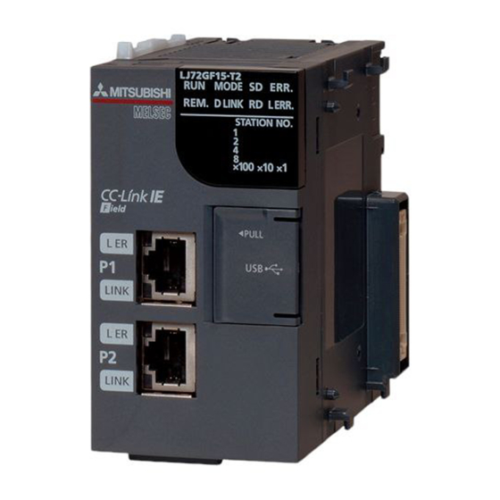
Page 22: Chapter 2 Part Names
CHAPTER 2 PART NAMES This chapter describes the part names of the head module. Name Description Indicates the operating status. Operating normally. (RUN state) Operating normally. (STOP state) • The switch of the head module is set to STOP. (Data transfer between the devices in the head module is stopped.) RUN LED Flashing... - Page 23 CHAPTER 2 PART NAMES Name Description Indicates the error status of the head module. The error details can be checked by performing the CC-Link IE Field Network diagnostics. ( Page 75, CHAPTER 9) ERR. LED An error has occurred in the head module. Operating normally.
- Page 24 Name Description Controls the operation of the head module. Resets the head module or switches it to test mode. Operate the switch with your fingers. Use of a tool such as a screw driver may damage the switch. • Reset method Hold the switch in the RESET/TEST position for 1 second or more.
- Page 25 CHAPTER 2 PART NAMES Remark ● Opening and closing the front cover of the head module The cover on the front of the head module is equipped with a stopper. If you open the cover until it clicks, it will stay open. Stopper Pull the cover so that the stopper will be set...
-
Page 26: Chapter 3 Specifications
CHAPTER 3 SPECIFICATIONS This chapter describes the specifications of the head module. General Specifications Item Specifications Operating ambient 0 to 55 temperature Storage ambient -25 to 75 temperature Operating ambient humidity 5 to 95%RH, non-condensing Storage ambient humidity Constant Frequency Half amplitude Sweep count acceleration... - Page 27 CHAPTER 3 SPECIFICATIONS Do not use or store the programmable controller under pressure higher than the atmospheric pressure of altitude 0m. Doing so may cause malfunction. When using the programmable controller under pressure, please consult your local Mitsubishi representative. This indicates the section of the power supply to which the equipment is assumed to be connected between the public electrical power distribution network and the machinery within premises.
-
Page 28: Performance Specifications
Performance Specifications For the specifications of the entire CC-Link IE Field Network, refer to the user's manual for the master/local module used. Item Specifications 1024 points, 2K bytes 1024 points, 2K bytes Maximum number of link points per station 2048 points, 256 bytes CC-Link IE Field 2048 points, 256 bytes Network part... - Page 29 CHAPTER 3 SPECIFICATIONS Item Specifications 4096 points, 512 bytes (Number of points accessible to the actual module) Number of I/O points 4096 points, 512 bytes (Number of points accessible to the actual module) 8192 points, 1K bytes (Number of points can be used in the program) (Assign RX0 from X0.) 8192 points, 1K bytes (Number of points can be used in the...
-
Page 30: Function List
Function List The following table lists the functions of the head module. Function Description Reference The input and output data of the modules connected to the head module can be Cyclic transmission Page 65, CHAPTER 8 used just like those of the master station. The master station and a local station can directly access the devices in the head module and the buffer memory in an intelligent function module. -
Page 31: Chapter 4 Procedures Before Operation
CHAPTER 4 PROCEDURES BEFORE OPERATION CHAPTER 4 PROCEDURES BEFORE OPERATION This chapter describes the procedures before operating the head module. Initial Start-up Procedure The following is the start-up procedure for using the head module for the first time. For start-up examples, refer to the User's manual for the master/local module used. - Page 32 Stating data link Page 20, CHAPTER 2 Page 65, CHAPTER 8 Start data link. Network diagnostics Page 75, CHAPTER 9 Check if the network can communicate normally by using CC-Link IE field network diagnostics. If the head module is powered on when there is no communication with the master station, it takes approximately five seconds to change to the RUN state.
-
Page 33: Procedure For Replacing The Head Module
CHAPTER 4 PROCEDURES BEFORE OPERATION Procedure for Replacing the Head Module The head module can be replaced without stopping the data link in the system. Even if the head module does not have a station number, it can be set from the CC-Link IE Field Network diagnostics of the master station. - Page 34 Setting the head module into RUN status Page 20, CHAPTER 2 Set the switch of the head module to "RUN." Temporary error invalid station cancel and link start User's manual for the master/local module used Cancel the temporary error invalid station setting on the master station, and start the link.
- Page 35 CHAPTER 4 PROCEDURES BEFORE OPERATION (3) Module replacement example Execute the read from PLC function and load parameters written in the head module to a project of GX Works2. [Online] [Read from PLC] Connect GX Works2 to the master station, and stop the data link from the CC-Link IE Field Network diagnostics.
-
Page 36: Chapter 5 System Configuration
CHAPTER 5 SYSTEM CONFIGURATION This chapter describes system configuration using a head module. For CC-Link IE Field Network configuration, refer to the following. User's manual for the master/local module used Head Module System Configuration The following figure shows a system configuration using a head module. I/O modules or intelligent function Power supply module... -
Page 37: Applicable System
CHAPTER 5 SYSTEM CONFIGURATION Applicable System (1) Connectable modules and the number of modules (a) Connectable modules MELSEC-L series modules can be connected to the head module. Note that there are some modules with restrictions or that can be connected but cannot be used. (b) Number of modules *1*2 Up to 10 I/O modules and intelligent function modules can be connected in total. -
Page 38: Chapter 6 Installation And Wiring
CHAPTER 6 INSTALLATION AND WIRING This chapter describes how to install and wire modules. Wiring Environment and Installation Position When installing modules in a control panel, fully consider its operability, maintainability, and environmental resistance. 6.1.1 Installation environment Install the programmable controller according to the installation environment shown in the general specifications. Page 24, Section 3.1) Do not install the programmable controller to the place where: •... -
Page 39: Installation
CHAPTER 6 INSTALLATION AND WIRING Installation This section describes how to interconnect modules and how to mount them on a DIN rail. ● Modules must be mounted on a DIN rail. ● Connect an END cover on the right of the terminal module. (1) Precautions for connecting and mounting modules •... -
Page 40: Connecting Modules
6.2.1 Connecting modules This section describes a procedure for connecting modules with an example of how to connect a head module to the L61P. Shut off the external power supply (all phases) used in the system before connecting or disconnecting modules. (1) Connecting procedure Release the module joint levers located at the top and bottom of the head module. - Page 41 CHAPTER 6 INSTALLATION AND WIRING (2) Disconnecting procedure Reverse the connecting procedure to disconnect the modules. ● Failure to securely lock the module joint levers until they click may cause malfunction, failure, or drop of the module. ● To slide the lever, use the projection of the lever. Sliding the lever with a part other than the projection may cause a difficulty of sliding.
-
Page 42: Mounting The Modules On A Din Rail
6.2.2 Mounting the modules on a DIN rail This section describes a procedure for mounting the modules on a DIN rail. The method for fixing the DIN rail stopper is an example. Fix the module in accordance with the manual for the DIN rail stopper used. - Page 43 CHAPTER 6 INSTALLATION AND WIRING Hitch the bottom hook of the DIN rail stopper to the bottom of the DIN rail. Hitch the hook according to the orientation of the arrow on the front of the stopper. Hitch the hook to bottom of the DIN rail Hitch the upper hook of the DIN rail stopper to the Hitch the hook to...
- Page 44 Do not slide modules from the edge of the DIN rail when mounting them. Doing so may damage the metal part located on the back of the module. (2) Removal procedure Reverse the mounting procedure to remove the modules from the DIN rail. (3) Applicable DIN rail models (IEC 60715) •...
-
Page 45: Changing Modules On A Din Rail
CHAPTER 6 INSTALLATION AND WIRING 6.2.3 Changing modules on a DIN rail This section describes a procedure for changing modules on a DIN rail by sliding them rightward. Remove the mounted terminal block and disconnect the connectors beforehand. Remove the DIN rail stopper on the right side. Pull down all DIN rail hooks on the back of the modules. - Page 46 Slide the modules and plug the connectors. Lock the module joint levers. Slide the levers toward the back side of the module until they click. Lock the DIN rail hooks and attach the DIN rail stopper. Page 40, Section 6.2.2) Do not slide modules from the edge of the DIN rail when mounting them.
-
Page 47: Wiring To The Power Supply Module
CHAPTER 6 INSTALLATION AND WIRING Wiring to the Power Supply Module For wiring to the power supply module, refer to the following. MELSEC-L CPU Module User's Manual (Hardware Design, Maintenance and Inspection) Testing the Head Module Before Wiring (1) Unit test Perform a unit test to check the hardware status of the head module. - Page 48 Unit test starts. The MODE LED starts flashing, and the 1 or 10 LED : On starts turning on and off repeatedly in the sequence of : Flashing 12481. The 1 or 10 LED stops turning on and off, and the When completed D LINK LED turns on when the test is completed.
-
Page 49: Wiring To The Head Module
CHAPTER 6 INSTALLATION AND WIRING Wiring to the Head Module This section describes the wiring to the head module. 6.5.1 Wiring This section describes how to connect an Ethernet cable to the head module and wiring precautions. For network configuration and cables/hubs required for wiring, refer to the following. User's manual for the master/local module used (1) Connecting an Ethernet cable (a) Connecting procedure... - Page 50 It is not necessary to distinguish between PORT1 and PORT2. • When only one connector is used in star topology, an Ethernet cable can be connected to either PORT1 or PORT2. Either port can be used. • When two connectors are used in line topology or ring topology, an Ethernet cable can be connected to the connectors in any combination.
-
Page 51: Grounding
CHAPTER 6 INSTALLATION AND WIRING 6.5.2 Grounding Observe the following: • Provide independent grounding when possible. Ground the FG and LG terminals of the programmable controller with a ground resistance of 100 or less. • If independent grounding cannot be provided, employ shared grounding (figure (2) below). Programmable Programmable Programmable... -
Page 52: Precautions
6.5.3 Precautions This section describes wiring precautions. (1) Laying Ethernet cables • Place the Ethernet cable in a duct or clamp them. If not, dangling cable may swing or inadvertently be pulled, resulting in damage to the module or cables or malfunction due to poor contact. •... -
Page 53: Chapter 7 Parameter Settings
CHAPTER 7 PARAMETER SETTINGS CHAPTER 7 PARAMETER SETTINGS This chapter describes parameter settings of the head module and modules connected to the head module. Open the setting windows by the following operation. Project window [Parameter] [PLC Parameter] Double-click. ● Set parameters for the entire network (such as the number of slave stations, link device assignment, reserved station specification, and temporary error invalid station setting) to the master station. -
Page 54: Plc Parameters
PLC Parameters This section describes details on PLC parameters together with their setting windows. Window Description Reference Parameter No. Communication Head Set parameters for connecting the head module to CC-Link IE 01F0H Page 53, Section 7.1 (1) Setting Field Network. PLC Name Set the label and comment of the head module. - Page 55 CHAPTER 7 PARAMETER SETTINGS (1) Communication Head Setting Set parameters for connecting the head module to CC-Link IE Field Network. Project window [Parameter] [PLC Parameter] "Communication Head Setting" The following table lists parameter items. Item Description Setting range Online/Offline Mode Select the mode of the head module.
- Page 56 (2) PLC Name Set the label and comment of the head module. Project window [Parameter] [PLC Parameter] "PLC Name" The following table lists parameter items. Item Description Setting range Up to 10 one-byte characters Label Enter the label (name or application) of the head module. (Default: Blank) Up to 64 one-byte characters Comment...
- Page 57 CHAPTER 7 PARAMETER SETTINGS (3) PLC System Set parameters for the system including the head module. Project window [Parameter] [PLC Parameter] "PLC System" The following table lists parameter items. Parameters other than "Remote Reset" do not need to be set to the head module. Item Description Setting range...
- Page 58 (4) PLC RAS Set parameters for the RAS function. Project window [Parameter] [PLC Parameter] "PLC RAS" The following table lists parameter items. Parameters other than "Module Error History Collection (Intelligent Function Module)" do not need to be set to the head module.
- Page 59 CHAPTER 7 PARAMETER SETTINGS (5) Operation Setting Set parameters to transfer data stored in the following head module devices as cyclic data. • Link special relay (SB) • Link special register (SW) • Special relay (SM) • Special register (SD) •...
- Page 60 Project window [Parameter] [PLC Parameter] "Operation Setting" The following table lists parameter items. Item Description Setting range Select a link device assignment method. • Points/Start Assignment Method • Points/Start: Enter the points and start numbers of link devices. • Start/End •...
- Page 61 CHAPTER 7 PARAMETER SETTINGS Item Description Setting range Transfer From • W: 0 to 1FFF • SB: 0 to 1FF0 • SW: 0 to 1FFF • SM: 0 to 2032 • SD: 0 to 2047 (Default: Blank) Start Enter the start number of the device to be transferred. Transfer To •...
- Page 62 (a) Setting example To transfer the link special relay (SB) data of the head module as cyclic data, transfer the link special relay (SB) value to the link register (W). Setting for Forwarding Parameter between Devices Transfer 1: Transfers the values in SB1040 to SB11FF to W1104 to W111F. Transfer 2: Transfers the value in W0000 to SB1000 to SB100F.
- Page 63 CHAPTER 7 PARAMETER SETTINGS (6) I/O Assignment Set connection status of each module. Project window [Parameter] [PLC Parameter] "I/O Assignment" The following table lists parameter items. Item Description Setting range Empty, Input, Output, Intelligent Type Set the type of a connected module. (Default: Blank) Up to 16 one-byte characters Model Name...
-
Page 64: Network Parameters
Network Parameters Set parameters of the CC-Link master/local module connected to the head module. Project window [Parameter] [Network Parameter] [CC-Link] For details, refer to the following. MELSEC-L CC-Link System Master/Local Module User's Manual Configure a CC-Link system so that the points of devices used for CC-Link communications (RX/RY/RWr/RWw) may be within the maximum link points per station. -
Page 65: Remote Password
CHAPTER 7 PARAMETER SETTINGS Remote Password Set a remote password to a serial communication module. Project window [Parameter] [Remote Password] The following table lists parameter items. Item Description Setting range Up to four one-byte characters (alphanumeric characters, special Password Setting Enter a remote password. -
Page 66: Intelligent Function Module Parameters
Intelligent Function Module Parameters Set intelligent function module parameters. Set parameters in the "New Module" window. Project window Right-click [Intelligent Function Module] [New Module] Item Description Setting range Module Type Select a module type. Module Selection Module Name Select a model name. Select the number of the slot where an intelligent function module Mounted Slot No. -
Page 67: Chapter 8 Cyclic Transmission
CHAPTER 8 CYCLIC TRANSMISSION CHAPTER 8 CYCLIC TRANSMISSION This chapter describes how to perform cyclic transmission of bit and word device data of the head module. Cyclic Transmission of Bit Device Data The input (X) and output (Y) data of the modules connected to the head module can be used just like those of the master station by performing cyclic transmission. - Page 68 (1) Data flow This section describes the cyclic transmission data flow of bit device data and the setting for transmission. • When data is input from an intelligent device station to the master station The input (X) data of each module connected to the head module is input to the remote input (RX) of the master station.
- Page 69 CHAPTER 8 CYCLIC TRANSMISSION (a) Data flow when "0000H" is set to the start number of RX/RY of the master station and the default I/O assignment setting for the head module is used Slot No. Slot 0 Slot 1 Slot 2 Slot 3 Start I/O No.
- Page 70 (b) Data flow when "0000H" is set to the start number of RX/RY of the master station and the I/O assignment setting for the head module is changed The I/O assignment setting is changed as shown below in this example. Slot No.
- Page 71 CHAPTER 8 CYCLIC TRANSMISSION (2) Data setting method In Network Configuration Setting of the master station, set the total number of points for the input/output (X/Y) of the modules connected to the head module, in 16-point units. In the case of the figure on the previous page, specify "0000" to "003F" for "RX/RY Setting". ●...
- Page 72 (3) Output status for each status Depending on the status of the data link and head module, data may not be able to be output. The following table summarizes how the status of the data link and head module affect the output (Y). : Not dependent on the status Head module Data link...
-
Page 73: Cyclic Transmission Of Word Device Data
CHAPTER 8 CYCLIC TRANSMISSION Cyclic Transmission of Word Device Data Word data, such as data stored in the buffer memory of the module connected to the head module, can be used in the word device of the master station by performing cyclic transmission. Master station Head module (Intelligent device station) - Page 74 (1) Data flow This section describes the cyclic transmission data flow of word device data and the setting for transmission. • When data is transferred from the master station to the intelligent device station The remote register (RWw) data of the master station is transferred to the buffer memory of the intelligent function module connected to the head module.
- Page 75 CHAPTER 8 CYCLIC TRANSMISSION (a) Data flow when "0000H" is set to the start number of RWw/RWr of the master station Master station Head module Digital-analog Station No.1 converter module Buffer memory 0000 0000 0000 to 0003 to 0003 to 0003 Station No.1 0007 0007...
- Page 76 (2) Data setting method Set the auto refresh of the intelligent function module connected to the head module. Specify the following devices as the devices to be auto refreshed. Item Setting range of auto refresh target device "Transfer to PLC" W1000 to W13FF "Transfer to intelligent function module"...
-
Page 77: Chapter 9 Cc-Link Ie Field Network Diagnostics
CHAPTER 9 CC-LINK IE FIELD NETWORK DIAGNOSTICS CHAPTER 9 CC-LINK IE FIELD NETWORK DIAGNOSTICS This chapter describes how to check error locations and causes by executing the CC-Link IE Field Network diagnostics using GX Works2. When GX Works2 is connected to the master station, the entire network status can be monitored. If the intelligent device station status cannot be monitored due to cable disconnection or any other error, directly connect GX Works2 to the head module. -
Page 78: Starting Diagnostics
Starting Diagnostics This section describes how to execute the CC-Link IE Field Network diagnostics. Connect GX Works2 to the head module. Start the CC-Link IE Field Network diagnostics from the menu. [Diagnostics] [CC IE Field Diagnostics] ● When another station has been specified as a connected station The CC-Link IE Field Network diagnostics cannot be started when another station has been specified in "Other Station Setting"... - Page 79 CHAPTER 9 CC-LINK IE FIELD NETWORK DIAGNOSTICS The head module status is displayed in "Selected Station Communication Status Monitor". ( Page 78, Section 9.3) If an error occurs, a button indicating the error (e.g. button) is displayed. Click the button to check the error details and actions to be taken.
-
Page 80: Diagnostic Window
Diagnostic Window This section describes items displayed in the "CC IE Field Diagnostics" window. (1) Displayed items Item Description Starts monitoring of the CC-Link IE Field Network diagnostics. button Monitor Status Stops monitoring of the CC-Link IE Field Network diagnostics. button Downloaded from ManualsNet.com... - Page 81 CHAPTER 9 CC-LINK IE FIELD NETWORK DIAGNOSTICS Item Description Displays the head module status. Displays the operating status. : Operating normally Selected Station Communication Status : Error (Data link continued) (yellow) Monitor : Error (Data link stopped) (red) Displays the mode. Displays the MAC address.
-
Page 82: Communication Test
Communication Test Communication test checks if transient transmission data can be properly routed from the own station to the communication target. For how to perform a test, refer to the following. User's manual for the master/local module used Cable Test Cable test checks if the Ethernet cables are properly connected. -
Page 83: System Monitor
CHAPTER 9 CC-LINK IE FIELD NETWORK DIAGNOSTICS System Monitor The "System Monitor" window opens. Errors that occur in modules other than the head module can also be checked. For details, refer to Page 89, Section 11.3. Remote Operation Remote operations (such as remote RUN, STOP, and RESET) can be performed from GX Works2 to the head module. Connect GX Works2 to the head module. -
Page 84: Chapter 10 Maintenance And Inspection
CHAPTER 10 MAINTENANCE AND INSPECTION This chapter describes items that must be maintained or inspected daily or periodically to properly use a programmable controller in optimal condition at all times. 10.1 Daily Inspection This section describes items that must be inspected daily. Check box The modules are securely installed. -
Page 85: Periodic Inspection
CHAPTER 10 MAINTENANCE AND INSPECTION 10.2 Periodic Inspection This section describes items that must be inspected once or twice every 6 to 12 months. The items must be inspected as well when the equipment has been relocated or modified, or wiring layout has been changed. -
Page 86: Chapter 11 Troubleshooting
CHAPTER 11 TROUBLESHOOTING This chapter describes errors that may occur in the head module, causes of the errors, and corrective actions. 11.1 Before Troubleshooting Check that the POWER LED of the power supply module is on. If it is off, troubleshoot the CPU module. MELSEC-L CPU Module User's Manual (Hardware Design, Maintenance and Inspection) ) 11.2 Troubleshooting Procedure... - Page 87 CHAPTER 11 TROUBLESHOOTING (1) Procedure Connect GX Works2 to the head module, and open the "System Monitor" window. [Diagnostics] [System Monitor] Select the module in which an error has occurred. • When the selected module is the head module Page 86, Section 11.2 (1) (a) •...
- Page 88 (a) Checking for an error of the head module Select the head module in the "System Monitor" window and click the button to open the "PLC Diagnostics" window. Select the error that is occurring, and click the How to start CC-Link IE field network diagnostics button to check the cause and action.
- Page 89 CHAPTER 11 TROUBLESHOOTING If data link cannot be performed even after troubleshooting by the above operation, perform the following. • CC-Link IE Field Network diagnostics by connecting GX Works2 to the master/local module ( User's manual for the master/local module used) •...
- Page 90 (b) Checking for an error of a module other than the head module Select a module other than the head module in the "System Monitor" window, and click the button to view the diagnostics or detailed information. Displays the latest error code.
-
Page 91: System Error History
CHAPTER 11 TROUBLESHOOTING 11.3 System Error History The history of the errors that occurred in the past can be checked so that corrective actions can be taken for each of them. The error that has occurred before the head module is reset or the system is powered off also can be checked. On a single window, the error history of not only the head module but also the intelligent function modules connected to the head module can be checked. - Page 92 (2) Precautions (a) When the time and date of the error is not correctly displayed • Check if the master station is connected to the head module. The head module periodically collects time information from the CPU module on the master station. If the master station is not connected to the head module, the time and date of errors will not be displayed correctly.
-
Page 93: Checking The Leds
CHAPTER 11 TROUBLESHOOTING 11.4 Checking the LEDs This section describes troubleshooting using the LEDs. (1) When the RUN LED turns off Check item Action Is the head module installed correctly? Connect the head module to the power supply module again. If the above action does not solve the problem, perform a unit test on the head module to check for a hardware failure. - Page 94 (5) When the D LINK LED turns off Check item Action • If an error has occurred in the CPU module on the master station, eliminate the cause of the CPU module error. ( User's manual for the master/local module used) Is the master station connected to the network and operating •...
- Page 95 CHAPTER 11 TROUBLESHOOTING (8) When the L ERR. LED turns on Check item Action • Check if 1000BASE-T-compliant Ethernet cables are used. Page 26, Section 3.2) Are the Ethernet cables correctly used and connected? • Check if the station-to-station distance is 100m or less. ( Page 50, Section 6.5.3) •...
- Page 96 (11)When the REM. LED turns off Check item Action Identify the error cause on the "System Monitor" window using GX Has an error occurred in the head module? Works2, and take action. ( Page 84, Section 11.2) Downloaded from ManualsNet.com search engine...
-
Page 97: Troubleshooting By Symptom
CHAPTER 11 TROUBLESHOOTING 11.5 Troubleshooting by Symptom This section describes troubleshooting methods by symptom. Perform these troubleshooting actions when cyclic and/or transient transmissions are not possible with the target station even though no error is detected in the head module. If an error has occurred in an intelligent function module installed with the head module, identify the cause of the error by using GX Works2. -
Page 98: List Of Error Codes
11.6 List of Error Codes This section describes error messages, error conditions, causes, and actions for respective error codes of the head module. Errors of the head module are classified by error codes as shown below. Error code Classification Reference 1 to 10000 Errors of the head module Page 97, Section 11.6 (1) - Page 99 CHAPTER 11 TROUBLESHOOTING (1) Error codes (1 to 10000) The following table lists the error messages, error conditions, causes, and actions of the error codes (1 to 10000). The "Supplementary information" in the "Error and cause" column can be checked by any of the following. •...
- Page 100 Error Error and cause Action code [SP. UNIT DOWN] • In the initial processing, no response is returned from the intelligent function module. • The buffer memory size of the intelligent function module is abnormal. • No response is returned from the intelligent function module. Reset the head module.
- Page 101 CHAPTER 11 TROUBLESHOOTING Error Error and cause Action code [END COVER ERR.] An error was detected in the END cover. ■Supplementary information 1720 • Common information: - • Individual information: - • Replace the END cover. ■Diagnostic timing • Reset the head module. •...
- Page 102 Error Error and cause Action code • Reduce the number of installed modules to 10 or less. [SP. UNIT LAY ERR.] • Remove the module installed in the position corresponding to the I/O points of • The number of installed modules has exceeded 10. 4096 or greater.
- Page 103 CHAPTER 11 TROUBLESHOOTING Error Error and cause Action code [LINK PARA. ERROR] A network refresh parameter for CC-Link is out of range. ■Supplementary information Correct the network parameter settings, and then write them. 3106 • Common information: File name/Drive name If the error occurs again even after the correction, the module may have failed.
- Page 104 Error Error and cause Action code [WDT ERROR] • I/O refresh processing time exceeded 200ms. Momentary 5000 power failure occurs frequently. ■Supplementary information Modify the power supply system to prevent momentary power failure. • Common information: Time (200ms) • Individual information: Time (value actually measured) 5001 ■Diagnostic timing •...
- Page 105 CHAPTER 11 TROUBLESHOOTING (2) Error codes (4000H to 4FFFH) If an error occurs at communication request from the programming tool, intelligent function module, or network system connected, the head module returns the error code (any of 4000H to 4FFFH) to the request source. This error code is not stored in SD0 because the error is not the one detected by the self-diagnostic function of the head module.
- Page 106 Error code Error Action • In the network configuration settings of the master station, cancel the reserved station setting. D0E1H Own station reserved • Change the station number of the head module to a station number that is not reserved. •...
- Page 107 CHAPTER 11 TROUBLESHOOTING Error code Error Action Target station No. error in transient Check that the command can be requested to all or a group of stations at the D20FH transmission request source, and retry the operation. Target station No. error in transient Correct the header information at the request source, and retry the D210H transmission...
- Page 108 Error code Error Action • Check the network status by executing the CC-Link IE Field Network diagnostics using the programming tool, and take action. D281H Transient reception failed • When the target station is overloaded and cannot receive transient data, send the data to the target/relay station after the load on the station is reduced.
- Page 109 CHAPTER 11 TROUBLESHOOTING Error code Error Action • The head module received transient data addressed to a different network. Target station No. error in transient Check the network number and target station number, and retry the D2AEH transmission operation. • Check if the routing parameters are correctly set. •...
- Page 110 Error code Error Action • Data link cannot be stopped because cyclic transmission has been Data link start/stop retry error (to D721H stopped. another station) • Data link cannot be started because cyclic transmission is in execution. • Data link cannot be stopped because cyclic transmission has been Data link start/stop retry error (to own D722H stopped.
- Page 111 CHAPTER 11 TROUBLESHOOTING Error code Error Action • A malfunction may have occurred due to noise. Check the wire and cable distances and grounding condition of each device, and take measures to reduce noise. D827H Communication RAM error • Execute a unit test for the head module. If a failure occurs again, the possible cause is a hardware failure of the head module.
- Page 112 Error code Error Action • A malfunction may have occurred due to noise. Check the wire and cable distances and grounding condition of each device, and take measures to reduce noise. DAF3H Flash ROM error • Execute a unit test for the head module. If a failure occurs again, the possible cause is a hardware failure of the head module.
-
Page 113: Appendices
APPENDICES APPENDICES Appendix 1 External Input/Output Forced On/Off This function forcibly turns on or off the external input/output of the head module. (1) Input/output operation when a forced on/off operation is performed Three types of forced on/off operations are available as shown in the following table. The following table shows the status of input (X) and output (Y) when a forced on/off operation is performed. - Page 114 (a) Number of devices that can be registered Up to 32 devices in total can be registered. (b) Checking the execution status • "Forced Input Output Registration/Cancellation" window of GX Works2 • Flashing of the MODE LED (green) (The MODE LED flashes in green when a device is registered.) •...
- Page 115 APPENDICES (2) Operating procedure Open the "Forced Input Output Registration/Cancellation" window. [Debug] [Forced Input Output Registration/Cancellation] Enter the target device to the "Device" column. The setting range in the "Device" column is X0 to X1FFF or Y0 to Y1FFF. Click the button for the intended operation. Button name Description Button name...
-
Page 116: Appendix 2 File Password 32
Appendix 2 File Password 32 This function sets write password and read password for each file stored in the head module. Files can be protected against tampering and theft by unauthorized persons. Head module Reading the file A File A GX Works2 Write password: AbcDEF12 Read password: XYZ98756... -
Page 117: Appendix 2.1 Setting File Passwords
APPENDICES Appendix 2.1 Setting file passwords This section describes the characters which can be used for the password, and the types of files that can be password- protected. If you forget the password, initialize the head module by executing the format PLC memory function using GX Works2, and write the project to the head module again. - Page 118 (5) Creating, changing, deleting, and disabling a password (a) Creating and changing a password Open the "Create/Change Password" window. [Online] [Password/Keyword] [New] Click the button. Select any of the following values for "Registration Condition". Read Protection Write Protection ...
- Page 119 APPENDICES (b) Deleting a password Open the "Delete Password" window. [Online] [Password/Keyword] [Delete] Click the button. Enter a password and click the button. The registration status appears as "Deleted". Click the button to delete the password. Downloaded from ManualsNet.com search engine...
- Page 120 (c) Disabling a password Open the "Input Disable Password" window. [Online] [Password/Keyword] [Disable] Click the button. Enter a password and click the button. The registration status appears as "Disabled". Click the button to disable the password. Downloaded from ManualsNet.com search engine...
-
Page 121: Appendix 2.2 Password Authentication Method
APPENDICES Appendix 2.2 Password authentication method The passwords are authenticated by the following methods. • By GX Works2 • By the MC protocol (1) Authentication by GX Works2 Whenever an online operation requiring password authentication is executed, the "Disable Password" window appears. - Page 122 (2) Authentication by the MC protocol To access a password-protected file from external devices using the MC protocol, the request message format of the MC protocol must be changed and a command for the file password 32 must be specified. Add "Keyword"...
-
Page 123: Appendix 3 End Cover
APPENDICES Appendix 3 END Cover This section describes the specifications of the END cover. For specifications of the END cover with ERR terminal (L6EC-ET), refer to the following. MELSEC-L CPU Module User's Manual (Hardware Design, Maintenance and Inspection) (1) Part names Do not remove this label as it is for maintenance. -
Page 124: Appendix 4 Link Special Relay (Sb)
Appendix 4 Link Special Relay (SB) The link special relay (SB) is turned on/off depending on various factors during data link. An error status of the data link can be checked by monitoring it. (1) Application of link special relay (SB) By using the link special relay (SB), the status of CC-Link IE Field Network can be checked from HMI (Human Machine Interfaces) as well as GX Works2. -
Page 125: Appendix 5 Link Special Register (Sw)
APPENDICES Appendix 5 Link Special Register (SW) The link special register (SW) stores the information during data link as numerical values. Error locations and causes can be checked by monitoring the values. (1) Application of link special register (SW) By using the link special register (SW), the status of CC-Link IE Field Network can be checked from HMI (Human Machine Interfaces) as well as GX Works2. - Page 126 Name Description Stores the network number of the own station. SW0040 Network number Range: 1 to 239 Stores the station number of the own station. SW0042 Station number Range: 1 to 120 (slave stations), FFFFH (station number not set) Stores the mode of the own station. 0: Online SW0043 Mode status...
- Page 127 APPENDICES Name Description Stores the connection status of the own station. 00H: Normal 01H: Normal (communication in progress on PORT1, cable disconnected on PORT2) 04H: Normal (loopback communication in progress on PORT1, cable disconnected on PORT2) Connection status (own 10H: Normal (cable disconnected on PORT1, communication in progress on PORT2) SW0064 station) 11H: Disconnecting (cable disconnected on PORT1 and PORT2)
-
Page 128: Appendix 6 Special Relay (Sm)
Appendix 6 Special Relay (SM) The special relay (SM) is an internal relay whose application is determined in the programmable controller. However, it can be turned on/off as needed to control the head module. The following table shows how to read the list of special relay areas. Item Description Special relay number... - Page 129 APPENDICES (1) Diagnostic information Set by Name Meaning Explanation (Set timing) OFF: No error • Turns on if an error is detected by diagnostics. Diagnostic error ON: Error • The on state remains even after the system returns to normal. Self-diagnostic OFF: No error •...
-
Page 130: Appendix 7 Special Register (Sd)
Appendix 7 Special Register (SD) The special register (SD) is an internal register whose application is determined in the programmable controller. However, data can be written to the special register to control the head module as needed. Data is stored in binary format if not specified. - Page 131 APPENDICES (1) Diagnostic information Set by Name Meaning Explanation (Set timing) • Stores the error code of an error detected by diagnostics. Diagnostic Diagnostic error • The stored data is the same as the latest information in error history and system error error code history.
- Page 132 Set by Name Meaning Explanation (Set timing) • Stores common information corresponding to the error code stored in SD0. • The following three types of information are stored here. • The error common information type can be determined by "common information category code"...
- Page 133 APPENDICES Set by Name Meaning Explanation (Set timing) • Stores individual information corresponding to the error code stored in SD0. • The following six types of information are stored here. • The error individual information type can be determined by "individual information SD16 category code"...
- Page 134 Set by Name Meaning Explanation (Set timing) Error code to be SD50 Error clear Stores the error code to be cleared. cleared • Each time the input voltage of the head module drops below 85% (AC power)/65% (DC AC/DC DOWN AC/DC DOWN SD53 power) of the rated voltage, the value is incremented by 1 and is stored here.
- Page 135 APPENDICES (2) System information Set by Name Meaning Explanation (Set timing) Stores the switch status of the head module. Head module SD200 Status of switch 0: RUN switch status (Switch change) 1: STOP/RESET • Stores the status of each LED of the head module in the following bit pattern. •...
- Page 136 Set by Name Meaning Explanation (Set timing) Number of points SD290 Stores the number of points assigned to X. The number of points is fixed to 8192. assigned to X Number of points SD291 Stores the number of points assigned to Y. The number of points is fixed to 8192. assigned to Y Number of points SD292...
- Page 137 APPENDICES (3) Drive information Set by Name Meaning Explanation (Set timing) Parameter Write (transfer) Stores the progress of writing (transfer) to the program memory (flash ROM) in SD681 memory write status display percentage (0 to 100%). "0" is set when the write (transfer) command is issued. (transfer) status (percentage) SD682...
-
Page 138: Appendix 8 Access Code And Attribute Code
Appendix 8 Access Code and Attribute Code The following table lists the access codes and attribute code that are set when accessing the head module by using the RIRD or RIWT instruction of the master/local module. Device type Name Unit Access code Attribute code Device... -
Page 139: Appendix 9 Emc And Low Voltage Directives
CE marking. (1) Sales representative in EU member states The sales representative in EU member states is: Company: MITSUBISHI ELECTRIC EUROPE B.V. Address: Mitsubishi-Electric-Platz 1, 40882 Ratingen, Germany Appendix 9.1 Measures to comply with the EMC Directive... - Page 140 (b) Immunity requirements Standard Test item Test description Value specified in standard EN61000-4-2 An electrostatic discharge is • 8kV: Air discharge Electrostatic discharge applied to the enclosure of • 4kV: Contact discharge the equipment. immunity 80% AM modulation @1kHz EN61000-4-3 An electric field is radiated •...
- Page 141 Use of EMI gaskets (sealing the clearance) can suppress undesired radiated emissions. The tests were conducted by Mitsubishi Electric Corporation using a control panel having damping characteristics of 37dB (maximum) and 30dB (average) (measured at 3m distance, 30 to 300MHz).
- Page 142 (4) Cables used for the modules connected to the head module When a cable connected to a module such as an I/O module is extended out of the control panel, use a shielded cable. If a shielded cable is not used or not grounded properly, the noise immunity will not meet the requirement. (a) Grounding a shielded cable •...
- Page 143 APPENDICES (c) Grounding a Ver.1.10-compatible CC-Link dedicated cable Ground the shield of a cable connected to the CC-Link module or any of the CC-Link stations which is the farthest from the input power inside the control panel within 30cm from the module or station. Ver.1.10-compatible CC-Link dedicated cable is a shielded cable Strip a part of the jacket of the cable as shown below and ground the exposed shield to the largest area.
- Page 144 (e) Connectors for external devices When using connectors for external devices with any of the following modules, take the noise reduction measures described below. • High-speed counter module • Positioning module • Flexible high-speed I/O control module [When shielded cables are connected] The following figure shows an example of wiring against noise when a connector (A6CON1) is used.
- Page 145 APPENDICES [When a duct is used (problematic example and modification example)] Wiring duct Relay Relay Drive Drive Relay unit unit Control panel The drive units are placed Programmable near the noise source. The controller connection cable between Noise source the programmable controller and drive units is too long.
- Page 146 (5) External power supply Use a reinforced or double insulated CE-marked external power supply, and ground the FG terminal. (External power supply used for the tests conducted by Mitsubishi: DLP-120-24-1 (manufactured by TDK- Lambda Corporation), PS5R-SF24 (manufactured by IDEC Corporation)) (6) Power supply modules •...
- Page 147 APPENDICES (12)CC-Link modules • To ground the Ver.1.10-compatible CC-Link dedicated cable, refer to Page 141, Appendix 9.1 (4) (c). • Keep each power cable connected to the external power supply terminal or module power supply terminal to 30m or less. •...
- Page 148 (13)CC-Link/LT modules • Use the module under the installation environment of Zone A . For the specified Zones of the following products, refer to the manual provided with each product. • CL1Y4-R1B1 • CL1Y4-R1B2 • CL1XY4-DR1B2 • CL1XY8-DR1B2 • CL1PSU-2A •...
- Page 149 APPENDICES (b) Noise filter (power supply line filter) A noise filter is effective for reducing conducted noise in the 10MHz or less frequency band. (Use of a noise filter can suppress noise.) The following are the installation precautions. • Do not bundle the cables on the input side and output side of the noise filter. If bundled, the noise on the output side is induced into the filtered cable on the input side.
-
Page 150: Appendix 9.2 Measures To Comply With The Low Voltage Directive
Appendix 9.2 Measures to comply with the Low Voltage Directive The Low Voltage Directive requires electrical equipment that is designed or adapted for use between 50 to 1000VAC or 75 to 1500VDC to satisfy the safety requirements. This section describes the precautions for use of the MELSEC-L series modules to comply with the Low Voltage Directive. - Page 151 APPENDICES (4) Control panel (a) Protection against electric shock Handle the control panel as follows to protect a person who does not have adequate knowledge of electrical installation from an electric shock. • Lock the control panel so that only a person who is trained and has acquired enough knowledge of electrical installation can open the panel.
-
Page 152: Appendix 10 General Safety Requirements
Appendix 10 General Safety Requirements When a programmable controller is powered on or off, normal control outputs may not be performed temporarily. This is because there is a time lag for the power to be turned on between the programmable controller power supply and the external power supply (especially, DC) for the control target. -
Page 153: Appendix 11 Calculating Heating Value Of Programmable Controller
APPENDICES Appendix 11 Calculating Heating Value of Programmable Controller The ambient temperature inside the control panel where a head module is installed must be 55 or less. It is necessary to know the average power consumption (heating value) of the equipment and devices installed inside the control panel when designing a heat release structure of the panel. - Page 154 The calculation formulas for the power consumption of each block are as follows. (1) Power consumption of power supply module The power conversion efficiency of the power supply module is approximately 70% and 30% of the output power is consumed as heat. As a result, 3/7 of the output power will be the power consumption. The calculation formula is as follows.
-
Page 155: Appendix 12 Processing Time
APPENDICES Appendix 12 Processing Time The calculation formula for the I/O response time of the head module is as follows: Rio = (Number of RX/RY points) 0.16 + (Number of RWw/RWr points) 5.5 + 430 + Ka + (Response time of the connected module) [s] The above formula calculates the average value when the number of RX/RY points is the same as the number of actual I/O points of the module connected to the head module, and an auto refresh of the same number of points as... -
Page 156: Appendix 13 Added And Changed Functions
Appendix 13 Added and Changed Functions The following table lists added and changed functions. Serial No. (first 5 digits) Added function GX Works2 version of the head module Addition of applicable modules (positioning module and simple motion module) "12072" or later Version 1.31H or later Page 35, Section 5.2) Indication of loopback execution by L ERR. -
Page 157: Appendix 14 Checking Serial Number And Function Version
APPENDICES Appendix 14 Checking Serial Number and Function Version The serial number and function version of the head module can be checked on any of the following: • Rating plate • Front of the module • System Monitor window in GX Works2 (1) Checking on the rating plate The rating plate is located on the side of the head module. - Page 158 (3) Checking on the System Monitor window The serial number and function version can be checked on the "Product Information List" window. [Diagnostics] [System Monitor] Serial number Function version Product number On the window, the serial number and function version of each intelligent function module can be checked as well.
-
Page 159: Appendix 15 External Dimensions
APPENDICES Appendix 15 External Dimensions (1) Head module (LJ72GF15-T2) DIN rail center (Unit: mm) (2) END cover (L6EC) DIN rail center (Unit: mm) Downloaded from ManualsNet.com search engine... -
Page 160: Index
INDEX ....97 Error codes (1 to 10000) ....103 Error codes (D000H to DFFFH) . - Page 161 ......14 ..... . . 28,55 Master station Remote RESET .
-
Page 162: Revisions
This manual confers no industrial property rights or any rights of any other kind, nor does it confer any patent licenses. Mitsubishi Electric Corporation cannot be held responsible for any problems involving industrial property rights which may occur as a result of using the contents noted in this manual. -
Page 163: Warranty
WARRANTY Please confirm the following product warranty details before using this product. 1. Gratis Warranty Term and Gratis Warranty Range If any faults or defects (hereinafter "Failure") found to be the responsibility of Mitsubishi occurs during use of the product within the gratis warranty term, the product shall be repaired at no cost via the sales representative or Mitsubishi Service Company. -
Page 164: Trademarks
TRADEMARKS Ethernet is a registered trademark of Fuji Xerox Co., Ltd. in Japan. The company names, system names and product names mentioned in this manual are either registered trademarks or trademarks of their respective companies. In some cases, trademark symbols such as ' ' or ' ' are not specified in this manual. - Page 165 Downloaded from ManualsNet.com search engine...
- Page 166 SH(NA)-080919ENG-J(1703)MEE MODEL: LJ72GF15-T2-U-E MODEL CODE: 13JZ48 HEAD OFFICE : TOKYO BUILDING, 2-7-3 MARUNOUCHI, CHIYODA-KU, TOKYO 100-8310, JAPAN NAGOYA WORKS : 1-14 , YADA-MINAMI 5-CHOME , HIGASHI-KU, NAGOYA , JAPAN When exported from Japan, this manual does not require application to the Ministry of Economy, Trade and Industry for service transaction permission.
Need help?
Do you have a question about the MELSEC L Series and is the answer not in the manual?
Questions and answers