Mitsubishi Electric MELSEC L Series User Manual
Digital-analog converter module
Hide thumbs
Also See for MELSEC L Series:
- Manual (238 pages) ,
- User manual (166 pages) ,
- Reference manual (498 pages)

Related Manuals for Mitsubishi Electric MELSEC L Series


Summary of Contents for Mitsubishi Electric MELSEC L Series
- Page 1 MELSEC-L Digital-Analog Converter Module User's Manual -L60DA4 -L60DAVL8 -L60DAIL8...
-
Page 3: Safety Precautions
SAFETY PRECAUTIONS (Read these precautions before using this product.) Before using this product, please read this manual and the relevant manuals carefully and pay full attention to safety to handle the product correctly. The precautions given in this manual are concerned with this product only. For the safety precautions of the programmable controller system, refer to the user's manual for the CPU module used. - Page 4 [Installation Precautions] WARNING ● Shut off the external power supply (all phases) used in the system before mounting or removing a module. Failure to do so may result in electric shock or cause the module to fail or malfunction. [Installation Precautions] CAUTION ●...
- Page 5 Do not remove the film during wiring. Remove it for heat dissipation before system operation. ● Mitsubishi Electric programmable controllers must be installed in control panels. Connect the main power supply to the power supply module in the control panel through a relay terminal block. Wiring and replacement of a power supply module must be performed by qualified maintenance personnel with knowledge of protection against electric shock.
- Page 6 [Disposal Precautions] CAUTION ● When disposing of this product, treat it as industrial waste.
-
Page 7: Conditions Of Use For The Product
CONDITIONS OF USE FOR THE PRODUCT (1) Mitsubishi programmable controller ("the PRODUCT") shall be used in conditions; i) where any problem, fault or failure occurring in the PRODUCT, if any, shall not lead to any major or serious accident; and ii) where the backup and fail-safe function are systematically or automatically provided outside of the PRODUCT for the case of any problem, fault or failure occurring in the PRODUCT. -
Page 8: Introduction
INTRODUCTION Thank you for purchasing the Mitsubishi Electric MELSEC-L series programmable controllers. This manual describes the functions and programming of a digital-analog converter module (hereafter abbreviated as D/A converter module). Before using this product, please read this manual and the relevant manuals carefully and develop familiarity with the functions and performance of the MELSEC-L series programmable controller to handle the product correctly. -
Page 9: Compliance With Emc And Low Voltage Directives
COMPLIANCE WITH EMC AND LOW VOLTAGE DIRECTIVES (1) Method of ensuring compliance To ensure that Mitsubishi Electric programmable controllers maintain EMC and Low Voltage Directives when incorporated into other machinery or equipment, certain measures may be necessary. Please refer to one of the following manuals. -
Page 10: Relevant Manuals
RELEVANT MANUALS (1) CPU module user's manual Manual name Description <manual number (model code)> Specifications of the CPU modules, power supply modules, display unit, MELSEC-L CPU Module User's Manual (Hardware Design, Maintenance and branch module, extension module, SD memory cards, and batteries, Inspection) information on how to establish a system, maintenance and inspection, and <SH-080890ENG, 13JZ36>... - Page 11 Memo...
-
Page 12: Table Of Contents
CONTENTS CONTENTS SAFETY PRECAUTIONS ............. 1 CONDITIONS OF USE FOR THE PRODUCT . - Page 13 7.5.2 Setting from a program ............63 CHAPTER 8 FUNCTIONS Mode.
- Page 14 APPENDICES Appendix 1 Details of I/O Signals........... 183 Appendix 1.1 Input signal.
-
Page 15: Manual Page Organization
MANUAL PAGE ORGANIZATION In this manual, pages are organized and the symbols are used as shown below. The following illustration is for explanation purpose only, and should not be referred to as an actual documentation. "" is used for screen names and items. The chapter of the current page is shown. - Page 16 Pages describing instructions are organized as shown below. The following illustration is for explanation purpose only, and should not be referred to as an actual documentation. Instruction name Execution condition of the instruction Structure of the instruction in the ladder mode shows the devices applicable to the instruction Setting side...
- Page 17 Detailed descriptions of the instruction Conditions for the error and error codes For the errors not described in this manual, refer to the following. MELSEC-L CPU Module User's Manual (Hardware Design, Maintenance and Inspection) Simple program example(s) and descriptions of the devices used...
- Page 18 • Instructions can be executed under the following conditions. Execution condition Any time During on On the rising edge During off On the falling edge Symbol No symbol • The following devices can be used. Internal device Link direct device Intelligent function Constant Others...
- Page 19 Pages describing the functions, I/O signals, and buffer memory areas are organized as shown below. The following illustration is for explanation purpose only, and should not be referred to as an actual documentation. An icon indicates a mode available. The meaning of each icon is as follows. Icon Description The corresponding buffer memory area, I/O signal, or function is common to the D/A converter modules regardless of the model.
-
Page 20: Terms
TERMS Unless otherwise specified, this manual uses the following terms. Term Description A memory in an intelligent function module, where data (such as setting values and monitoring values) exchanged with Buffer memory a CPU module are stored D/A converter module A generic term for the L60DA4, L60DAVL8, and L60DAIL8 Display unit A liquid crystal display to be attached to the CPU module... -
Page 21: Chapter 1 D/A Converter Module
CHAPTER 1 D/A CONVERTER MODULE CHAPTER 1 D/A CONVERTER MODULE This chapter describes the application and features of the D/A converter module. Application The D/A converter module converts the digital data received from the CPU module to the analog signal and outputs the signal to external devices. -
Page 22: Features
Features (1) Features common to the D/A converter module (a) Scale conversion This function converts a digital value to the ratio value (%) in any width to represent the digital value in a numeric value easy to understand. (b) Error detection and monitoring When the digital value exceeds the specified range, the module detects an warning so that the digital value error monitoring and the output control are enabled. -
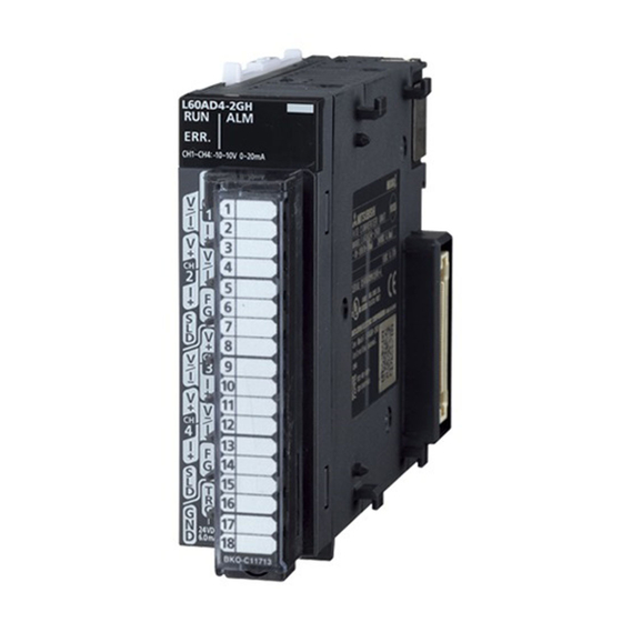
Page 23: Chapter 2 Part Names
CHAPTER 2 PART NAMES CHAPTER 2 PART NAMES The following table shows the part names of the D/A converter module. • L60DA4 • L60DAVL8, L60DAIL8... - Page 24 Name Description Module joint levers Levers for connecting two modules Displays the operating status of the D/A converter module. On: The module is operating normally. RUN LED (green) Flashing: In the offset/gain setting mode Off: The 5V power off or watchdog timer error has occurred. Displays the errors and status of the D/A converter module.
-
Page 25: Chapter 3 Specifications
CHAPTER 3 SPECIFICATIONS CHAPTER 3 SPECIFICATIONS This chapter describes general specifications, performance specifications, function list, list of I/O signals, and list of buffer memory addresses. General Specifications For the general specifications of the D/A converter module, refer to the following. "Safety Guidelines", the manual provided with the CPU module or head module... -
Page 26: Performance Specifications
Performance Specifications The following table shows the performance specifications of the D/A converter module. (1) L60DA4 Model Item L60DA4 Number of analog output channels 4 channels -20480 to 20479 Digital input (When the scaling function is used: -32768 to 32767) Voltage -10 to 10 VDC (external load resistance 1k... - Page 27 CHAPTER 3 SPECIFICATIONS (2) L60DAVL8 Model Item L60DAVL8 Number of analog output channels 8 channels -16384 to 16383 Digital input (When the scaling function is used: -32768 to 32767) Analog output Voltage -10 to 10 VDC (external load resistance 1k to 1M) Analog output range Digital value Resolution...
- Page 28 (3) L60DAIL8 Model Item L60DAIL8 Number of analog output channels 8 channels -8192 to 8191 Digital input (When the scaling function is used: -32768 to 32767) Analog output Current 0 to 20 mADC (external load resistance 0 to 600)) Analog output range Digital value Resolution 0 to 20mA...
-
Page 29: Number Of Parameter Settings
CHAPTER 3 SPECIFICATIONS 3.2.1 Number of parameter settings Set the initial setting of D/A converter module and the parameter setting of auto refresh setting so that the number of parameters, including these of other intelligent function modules, does not exceed the number of parameters that can be set in the CPU module. -
Page 30: Function List
Function List The following shows the function list of the D/A converter module. Item Description Reference This function sets whether to enable or disable D/A conversion for each channel. Disabling the Page 70, D/A conversion enable/disable function D/A conversion for unused channels reduces the conversion cycles. Section 8.2 This function sets whether to output the D/A converted value or the offset value, for each channel. -
Page 31: I/O Signal List
CHAPTER 3 SPECIFICATIONS I/O Signal List The following shows the I/O signal list of the D/A converter module. For details on the setting status, refer to the following. • Details of I/O Signals ( Page 183, Appendix 1) Input signal Output signal Device number Signal name... -
Page 32: List Of Buffer Memory Address
List of Buffer Memory Address The following shows the buffer memory list of the D/A converter module. For details on buffer memory, refer to the following. • Details of Buffer Memory Addresses ( Page 190, Appendix 2) Do not write data to the system areas and read-only areas in the buffer memory. Writing data to these areas may lead the module to malfunction. - Page 33 CHAPTER 3 SPECIFICATIONS Name Item enabled by Address Address turning on and off Default Read/Write (decimal) (hexadecimal) Operating condition L60DA4 L60DAVL8, L60DAIL8 setting request (Y9) 000FH (DA4) Scaling enable/disable setting 00FFH (DAL8) CH1 Scaling lower limit value CH1 Scaling upper limit value ...
- Page 34 Name Item enabled by Address Address turning on and off Default Read/Write (decimal) (hexadecimal) Operating condition L60DA4 L60DAVL8, L60DAIL8 setting request (Y9) Mode switching setting 160 to 199 A0H to C7H System area Pass data classification System area ...
- Page 35 CHAPTER 3 SPECIFICATIONS Name Item enabled by Address Address turning on and off Default Read/Write (decimal) (hexadecimal) Operating condition L60DA4 L60DAVL8, L60DAIL8 setting request (Y9) CH5 User range settings System area gain value CH6 User range settings System area ...
- Page 36 Name Item enabled by Address Address turning on and off Default Read/Write (decimal) (hexadecimal) Operating condition L60DA4 L60DAVL8, L60DAIL8 setting request (Y9) 1026 402H CH2 Wave pattern start address setting (L) 5000 1027 403H CH2 Wave pattern start address setting (H) 1028 404H CH3 Wave pattern start address setting (L)
- Page 37 CHAPTER 3 SPECIFICATIONS Name Item enabled by Address Address turning on and off Default Read/Write (decimal) (hexadecimal) Operating condition L60DA4 L60DAVL8, L60DAIL8 setting request (Y9) CH7 Wave pattern output 1062 426H System area repetition setting CH8 Wave pattern output 1063 427H System area...
- Page 38 Name Item enabled by Address Address turning on and off Default Read/Write (decimal) (hexadecimal) Operating condition L60DA4 L60DAVL8, L60DAIL8 setting request (Y9) CH5 Wave output 1116 45CH System area conversion cycle monitor (L) CH5 Wave output 1117 45DH System area conversion cycle monitor (H) CH6 Wave output 1118...
- Page 39 CHAPTER 3 SPECIFICATIONS Name Item enabled by Address Address turning on and off Default Read/Write (decimal) (hexadecimal) Operating condition L60DA4 L60DAVL8, L60DAIL8 setting request (Y9) 1150 47EH CH3 Wave output current digital value monitor 1151 47FH CH4 Wave output current digital value monitor ...
- Page 40 Name Item enabled by Address Address turning on and off Default Read/Write (decimal) (hexadecimal) Operating condition L60DA4 L60DAVL8, L60DAIL8 setting request (Y9) 1178 49AH CH4 Wave output warning Address monitor (L) 1179 49BH CH4 Wave output warning Address monitor (H) CH5 Wave output warning 1180 49CH...
- Page 41 CHAPTER 3 SPECIFICATIONS Name Item enabled by Address Address turning on and off Default Read/Write (decimal) (hexadecimal) Operating condition L60DA4 L60DAVL8, L60DAIL8 setting request (Y9) CH7 Analog output 1722 6BAH System area command value CH7 Analog output 1723 6BBH System area ...
- Page 42 (2) Un\G1800 to Un\G4999 (Error history) Item enabled by Address Address turning on and off Name Default Read/Write (decimal) (hexadecimal) Operating condition setting request (Y9) 1800 708H Latest address of error history 1801 709H System area ...
- Page 43 CHAPTER 3 SPECIFICATIONS (3) Un\G5000 to Un\G54999 (Wave data registry area) Item enabled by Address Address turning on and off Name Default Read/Write (decimal) (hexadecimal) Operating condition setting request (Y9) 5000 to 1388H to Wave data registry area 54999 D6D7H This is a value to be set after power-on or after the CPU module is reset.
-
Page 44: Chapter 4 Procedures Before Starting The Operation
CHAPTER 4 PROCEDURES BEFORE STARTING THE OPERATION This chapter describes the procedures before starting the operation. Start Module connecting Connect the D/A converter module in any desired configuration. Wiring Connect external devices to the D/A converter module. Are user range settings used? Offset/gain setting To use user range settings, configure the offset/gain setting. - Page 45 CHAPTER 4 PROCEDURES BEFORE STARTING THE OPERATION Memo...
-
Page 46: Chapter 5 System Configuration
CHAPTER 5 SYSTEM CONFIGURATION This chapter describes the overall configuration, number of connectable modules, and compatible software version of the D/A converter module. Overall System Configuration The following shows a system configuration example for using the D/A converter module. (1) When connected to a CPU module Display unit (optional) I/O module or... -
Page 47: Applicable System
CHAPTER 5 SYSTEM CONFIGURATION Applicable System (1) Number of connectable modules For the number of connectable modules, refer to the following. MELSEC-L CPU Module User's Manual (Hardware Design, Maintenance and Inspection) MELSEC-L CC-Link IE Field Network Head Module User's Manual (2) Compatible software version For compatible software version, refer to the following. -
Page 48: Chapter 6 Installation And Wiring
CHAPTER 6 INSTALLATION AND WIRING This chapter describes the installation and wiring of the D/A converter module. Installation Environment and Installation Position For precautions for installation environment and installation position, refer to the following. MELSEC-L CPU Module User's Manual (Hardware Design, Maintenance and Inspection) MELSEC-L CC-Link IE Field Network Head Module User's Manual... -
Page 49: Terminal Block
CHAPTER 6 INSTALLATION AND WIRING Terminal Block (1) Precautions Tighten the terminal block screws within the following specified torque range. Screw type Tightening torque range Terminal screw (M3 screw) 0.42 to 0.58Nm Terminal block mounting screw (M3.5 screw) 0.66 to 0.58Nm The following table shows the applicable solderless terminal installed to the terminal block. - Page 50 (b) L60DAVL8 Terminal block Pin number Signal name +24V +24V (c) L60DAIL8 Terminal block Pin number Signal name +24V +24V...
- Page 51 CHAPTER 6 INSTALLATION AND WIRING (3) Removal and installation of the terminal block The following shows how to remove and install the terminal block. (a) Removal procedure Open the terminal cover and loosen the terminal block mounting screw. Terminal block mounting screw Using the terminal block fixing holes as a fulcrum, remove the terminal block.
-
Page 52: Wiring
Wiring (1) Wiring to a terminal block The following shows wirings to a terminal block. (a) L60DA4 • For voltage output +24V • For current output +24V... - Page 53 CHAPTER 6 INSTALLATION AND WIRING (b) L60DAVL8 +24V (c) L60DAIL8 +24V...
-
Page 54: External Wiring
External Wiring The following describes the external wiring. (1) L60DA4 (a) For voltage output Motor drive module or others to 1M conversion Motor drive module Shield or others to 1M Motor drive module or others to 1M conversion Motor drive module Shield or others to 1M... - Page 55 CHAPTER 6 INSTALLATION AND WIRING (b) For current output Motor drive module or others 0 to 600 conversion Motor drive module Shield or others 0 to 600 Motor drive module or others 0 to 600 conversion Motor drive module Shield or others 0 to 600 +24V...
- Page 56 (3) L60DAIL8 Motor drive module or others 0 to 600 conversion Shield +24V 24VDC Filter For wire, use the shielded twisted pair cable. If noise or ripple occurs for analog signals, connect a capacitor with the value of 0.1 to 0.47F (withstand voltage 25V or higher) to the input terminal of an external device.
-
Page 57: Chapter 7 Various Settings
CHAPTER 7 VARIOUS SETTINGS CHAPTER 7 VARIOUS SETTINGS This chapter describes the setting procedures of the D/A converter module. ● After writing the contents of new module, parameter settings, and auto refresh settings into the CPU module, reset the CPU module, switch STOP RUN STOP RUN, or switch OFF ON the power supply to enable the setting contents. -
Page 58: Switch Setting
Switch Setting Set the output range, HOLD/CLEAR function, drive mode, and output mode used for each channel. (1) Setting procedure Open the "Switch Setting" window. Project window [Intelligent Function Module] module name [Switch Setting] Item Description Setting value • 4 to 20mA (default value) •... - Page 59 CHAPTER 7 VARIOUS SETTINGS Item Description Setting value • Normal output mode (conversion speed: 20s/CH) (default value) • Wave output mode (conversion speed: L60DA4 50s/CH) • Wave output mode (conversion speed: Set the output mode of the D/A converter Output mode setting 80s/CH) module.
-
Page 60: Parameter Setting
Parameter Setting Set the parameters of each channel. By setting the parameters, the setting by programming is not required. (1) Setting procedure Open the "Parameter" window. Start "Parameter" Project window [Intelligent Function Module] module name [Parameter] Pull-down list type Text box type Double-click the item to change the setting, and input the setting value. -
Page 61: Auto Refresh
CHAPTER 7 VARIOUS SETTINGS Auto Refresh Set the buffer memory of the D/A converter module to be refreshed automatically. By the auto refresh setting, reading/writing data by programming becomes unnecessary. (1) Setting procedure Open the "Auto_Refresh" window. Start "Auto_Refresh" Project window [Intelligent Function Module] module name [Auto_Refresh]... -
Page 62: Offset/Gain Setting
Offset/Gain Setting When using the user range setting, configure the offset/gain setting with the following operations. When the factory default setting is used, the offset/gain setting is not required. The offset/gain setting can be configured by the following two types of operations. •... - Page 63 CHAPTER 7 VARIOUS SETTINGS Specify the channel to use the offset/gain setting. Use the radio button to specify whether to perform the offset setting or gain setting. (Step 5 and later describe when the offset setting is specified.) ...
- Page 64 The adjustment amount of the offset value or gain value can be selected from "1", "100", "500", "1000", "2000", and "3000" or it can be set by inputting any value (1 to 3000). Clicking the button finely adjusts the analog output voltage value or analog output current value corresponding to the set adjusted value.
-
Page 65: Setting From A Program
CHAPTER 7 VARIOUS SETTINGS 7.5.2 Setting from a program (1) Setting procedure The following describes the procedures when setting the offset/gain from a program. Start Turns on Channel change request (YB). Switches to the Offset/gain setting mode. Checks that Channel change completed flag (XB) is on. - Page 66 The following shows the procedure for switching the mode (normal output mode offset/gain setting mode or offset/gain setting mode normal output mode). • Dedicated instruction (G(P).OFFGAN) ( Page 223, Appendix 5.2) • Setting to Mode switching setting (Un\G158, Un\G159) and OFF ON OFF of Operating condition setting request (Y9) ( Page 198, Appendix 2 (15)) •...
- Page 67 CHAPTER 7 VARIOUS SETTINGS (b) Switching the mode by the dedicated instruction (G.OFFGAN) This program performs as follows: • Switches the mode to the offset/gain setting mode by the dedicated instruction (G.OFFGAN). • Switches the channels for which the offset/gain settings are configured. •...
- Page 68 (c) Switching the mode by Mode switching setting (Un\G158, Un\G159) and Operating condition setting request (Y9) Normal output mode initial setting D/A conversion enable/disable setting Setting programs for other initial setting items Turns on Operating condition setting request (Y39).] Switches to the Offset/gain setting mode Sets 4144 to Mode switching setting (U3\G158).
-
Page 69: Chapter 8 Functions
CHAPTER 8 FUNCTIONS CHAPTER 8 FUNCTIONS This chapter describes the details on functions that can be used in the D/A converter module and the setting procedures. For details on I/O signals and buffer memory, refer to the following. • Details of I/O Signals ( Page 183, Appendix 1) •... - Page 70 (3) Mode transitions The following shows the transition condition of each mode. At the power-on or at the reset of the CPU module Offset/gain Wave output mode setting mode Normal output mode Transition condition Set "Drive Mode Setting" to "Normal (D/A Converter Processing) Mode" and set "Output mode setting" to "Normal Output Mode" in "Switch Setting"...
- Page 71 CHAPTER 8 FUNCTIONS (4) Checking method The current mode of the module can be checked by referring to the following table. (a) L60DA4 Stored value in Output Offset/gain setting mode flag Mode RUN LED status mode (Un\G9) (XA) Normal output mode (conversion speed: 20s/CH) Wave output mode (conversion speed: 50s/CH) Wave output mode (conversion speed: 80s/CH) Offset/gain setting mode...
-
Page 72: D/A Conversion Enable/Disable Function
D/A Conversion Enable/Disable Function Common This function sets whether to enable or disable D/A conversion for each channel. Disabling the D/A conversion for unused channels reduces the conversion cycles. (1) Setting procedure Set "D/A conversion enable/disable setting" to "0: Enable". Project window [Intelligent Function Module] module name... -
Page 73: Analog Output Hold/Clear Function
CHAPTER 8 FUNCTIONS Analog Output HOLD/CLEAR Function Common This function sets whether to hold the output analog value (HOLD) or clear the output analog value (CLEAR) when the CPU module operating status is RUN, STOP, or stop error. (1) Combination of analog output status The analog output status of the D/A converter module in the normal output mode differs from the status in the wave output mode, as described in (a) and (b). - Page 74 (b) Wave output mode The analog output status changes as shown in the following table, depending on the combination of settings for D/A conversion enable/disable setting (Un\G0), CH Output enable/disable flag (Y1 to Y8), and the wave output status. D/A conversion enable/disable setting Enable Disable...
- Page 75 CHAPTER 8 FUNCTIONS (2) Setting procedure Configure the setting from "HOLD/CLEAR function". Project window [Intelligent Function Module] module name [Switch Setting]...
- Page 76 (3) When using the analog output HOLD/CLEAR function with the module connected to the head module The following describes the conditions for using the analog output HOLD/CLEAR function when the analog I/O module is connected to the head module. • Enable the station-based block data assurance of the cyclic data on the send side. •...
-
Page 77: Analog Output Test When Cpu Module Is In Stop Status
CHAPTER 8 FUNCTIONS Analog Output Test when CPU Module is in STOP Status Common Analog output tests can be carried out when the CPU module is in the STOP status. The following functions are enabled during the analog output test. •... - Page 78 (2) Operation timing By forcibly turning OFF ON CH Output enable/disable flag (Y1 to Y8) when the CPU module is in the STOP status, an analog output value is changed from an offset value to a D/A-converted analog value. The following shows the relation between CH1 Output enable/disable flag (Y1) and analog output value when the CPU module is in STOP status.
-
Page 79: Scaling Function
CHAPTER 8 FUNCTIONS Scaling function Common This function scales a digital value into a value within the range of the set scaling lower limit value to scaling upper limit value. The programming for scale conversion can be omitted. However, this function cannot be used in the wave output mode. (1) Concept of scaling setting The setting for scaling lower and upper limit values differs depending on either the factory default setting or the user range setting is used for analog output range. - Page 80 (3) Setting procedure Set "D/A conversion enable/disable setting" to "0: Enable". Project window [Intelligent Function Module] module name [Parameter] Set "Scaling enable/disable setting" to "0: Enable". Set values for "Scaling upper limit value" and "Scaling lower limit value". Item Setting range Scaling upper limit value -32000 to 32000 Scaling lower limit value...
- Page 81 CHAPTER 8 FUNCTIONS (4) Scaling setting example When the settings are configured as shown below for a channel with the output range of 0 to 5V for the L60DA4 • "Scaling upper limit value": 16000 • "Scaling lower limit value": 4000 The following shows the digital values before and after scaling.
- Page 82 When the settings are configured as shown below for a channel with the output range of -10 to 10V for the L60DA4 • "Scaling upper limit value": 16000 • "Scaling lower limit value": 4000 The following shows the digital values before and after scaling. Analog output voltage (V) -10V Digital value...
- Page 83 CHAPTER 8 FUNCTIONS When the settings are configured as shown below for a channel with the user range setting of -8 to 8V for the L60DA4 • "Scaling upper limit value": 16000 • "Scaling lower limit value": 4000 The following shows the digital values before and after scaling. Analog output voltage (V) Digital value -20480...
- Page 84 ● When using the scaling function, the digital value before scaling can be set to a value out of the range of scaling upper and lower limit values (dotted line area in the I/O characteristics). However, use the scaling function within the range of analog output practical range (solid line area in the I/O characteristics).
-
Page 85: Warning Output Function
CHAPTER 8 FUNCTIONS Warning Output Function Common This function outputs a warning when the digital value exceeds the warning output upper limit value or becomes less than the warning output lower limit value. The warning target depends on the output mode as shown below. •... - Page 86 (2) Operation of warning output function When the digital value moves above the warning output upper limit value, or below the warning output lower limit value, warning notifications are made, and the analog output value becomes any of the following. •...
- Page 87 CHAPTER 8 FUNCTIONS Set values for "Warning output upper limit value" and "Warning output lower limit value". Item Setting range Warning output upper limit value -32768 to 32767 Warning output lower limit value Set the values so that they satisfy the condition of "Warning output upper limit value" > "Warning output lower limit value". In the channel where a value does not satisfy the condition, an error occurs.
-
Page 88: Wave Output Function
Wave Output Function Common This function registers the prepared wave data (digital value) into the D/A converter module and continuously outputs the data (analog value) in the set conversion cycle. A faster and smoother control than a program control is achieved by the automatic output of the control wave data registered in the D/A converter module for the analog (torque) control such as pressing machines and injection molding units. - Page 89 CHAPTER 8 FUNCTIONS Wave data 1) Create wave data. Wave data can be created with easy mouse operation from "Create Wave Output Data" of GX Works2. Wave data registry area 2) Save the wave data to a CSV file or file register. Save a CSV file in a SD memory card.
- Page 90 (1) Wave output function procedure The following shows how to use the wave output function. Start Initial settings of the wave output function Creating wave data Setting parameters of the wave output function Writing data to a file register (ZR) or CSV file Switch setting and basic setting Execution of the wave output function...
- Page 91 CHAPTER 8 FUNCTIONS The wave data creation and parameter setting of the wave output function can be executed easily with "Create Wave Output Data" of GX Works2. These setting contents are saved in the file register (ZR) of the CPU module or in a CSV file and registered to the buffer memory of the D/A converter module with the function block (FB) for the wave data registration.
- Page 92 (a) Feature of a file register (ZR) and a CSV file concerning wave data storage • File register (ZR): The wave data and parameter setting contents remain in the CPU module even after power ON OFF or reset of the CPU module. •...
- Page 93 CHAPTER 8 FUNCTIONS (4) Wave data The wave data indicates the time-series arrangement of the digital value to be output in analog value. Up to 50000 points can be used. The wave data is registered in Wave data registry area (Un\G5000 to Un\G54999). (5) Wave pattern To use the wave output function, select any points from the registered wave data for each channel to set the wave pattern.
- Page 94 Setting example to output the same wave from CH1 to CH3 CH1 to CH3 Wave pattern Wave data registry area (Un\G5000 to Un\G54999) 50000 data Wave data registry area Wave data registry area (Un\G5000) (Un\G54999) Setting item Buffer memory address Setting value CH1 Wave pattern start address setting Un\G1024, Un\G1025...
- Page 95 CHAPTER 8 FUNCTIONS The following section describes "repeat control" in which the same wave pattern is output repeatedly from the D/A converter module. (a) When the digital values are same for the start point and the end point An end point of a wave pattern overlaps with the start point of the wave pattern of the next iteration in the D/A converter module's processing;...
- Page 96 (b) When the digital values are different between the start point and the end point The wave pattern end point is output in analog as it is. In addition, the set wave pattern is repeatedly output in analog regardless of the setting in CH Wave pattern output repetition setting (Un\G1056 to Un\G1063). A wave pattern that is repeatedly Analog output output in an analog value...
- Page 97 CHAPTER 8 FUNCTIONS (7) Wave output conversion cycle The wave output conversion cycle is calculated by the following formula. Number of channels where Constant for wave output Conversion cycle ( s) Conversion speed D/A conversion is enabled conversion cycle In the wave output function, the conversion cycle can be set for each channel by setting CH Constant for wave output conversion cycle (Un\G1064 to Un\G1071).
-
Page 98: Initial Settings Of The Wave Output Function
8.8.1 Initial settings of the wave output function For the wave output function, set the following items as the initial setting. Before using the wave output function, complete the procedures described in this section. • Creating wave data ( Page 96, Section 8.8.1 (1)) •... - Page 99 CHAPTER 8 FUNCTIONS Select the graph displayed in "Register wave pattern" and press the key. Enter The "Register Wave Pattern" window is displayed. Press the key. Enter Set "Wave pattern information". Item Description Setting range The wave pattern number selected in the "Create Wave Output Data" Wave pattern No.
- Page 100 Click any position on the wave graph to create an end point. The created end point is displayed with Created end point To delete the end point, move the mouse pointer to the point. Then select "Delete end point" from the right-click menu.
- Page 101 CHAPTER 8 FUNCTIONS Set the wave between end points from the right-click menu or in "Specify wave" of "Wave details setting". This setting enables the wave change in the specified interval as follows. Item Setting result The interval of the start point and end point is drawn in an arc. When the circular arc is selected, the arc direction can be set in "Direction";...
- Page 102 Item Setting result The graph is drawn with an adjustment so that the start point and end point are on the edge points of the exponential function of y = e (X = 0 to 10). Exponential function The graph is drawn with an adjustment so that the start point and end point are on the edge points of the logarithmic function of y = X (X = 1 to 101).
- Page 103 CHAPTER 8 FUNCTIONS Drag the created end point to adjust the position. Drag The end point position also can be adjusted by changing the value of "End point" and "Digital value" in "Wave details setting". Item Description The end point of the previous interval is displayed. To change the start point, change the end Start point point of the previous interval.
- Page 104 Click the button. The saved wave pattern can be opened by clicking the button. Set the save destination and the file name, then click the button. Click the button. Click the button in "Register Wave Pattern" to register the created wave pattern. Repeat procedures 3 to 12 to create other wave pattern.
-
Page 105: Setting Parameters Of The Wave Output Function
CHAPTER 8 FUNCTIONS (2) Setting parameters of the wave output function Set the parameters of the wave output function in "Create Wave Output Data" of GX Works2. Before the parameter setting, create the wave data. Start "Create Wave Output Data". [Tool] [Intelligent Function Module Tool] [Analog Module]... - Page 106 Item Description Setting range ■L60DA4 • For 4 to 20mA, 0 to 20mA, 1 to 5V, 0 to 5V: 0 to 20479 (practical range: 0 to 20000) • For -10 to 10V: -20480 to 20479 Set the value to be output while the wave output is stopped. This setting (practical range: -20000 to 20000) is enabled only when "Output setting during wave output stop"...
- Page 107 CHAPTER 8 FUNCTIONS Set the save destination and the file name, then click the button. Click the button.
-
Page 108: Writing Data To A File Register (Zr) Or Csv File
(3) Writing data to a file register (ZR) or CSV file Write the wave data and the parameter setting of the wave output function to the file register (ZR) or the CSV file. Data not necessary for control such as "Wave pattern name", "Comment", and "Wave details setting" are not written to the file register (ZR) or CSV file. - Page 109 CHAPTER 8 FUNCTIONS Click the button. Click the button. Click the button in "Create Wave Output Data" to finish the window. Write the device memory to the CPU module from "Write to PLC...". [Online] [Write to PLC...]...
- Page 110 (b) Writing data to a CSV file When writing the data to the CSV file, store the CSV file to an SD memory card. Click the button in "Create Wave Output Data". Click the button. Set the save destination and the file name, then click the button.
- Page 111 CHAPTER 8 FUNCTIONS Some oscilloscopes or pulse generators can output the input wave or output wave to the CSV file. To output the wave with the wave output function by using the CSV file data, convert the data format into the one described in the following manual. In addition, convert the fractional value into the integer because the fractional value is unavailable in the wave output function.
-
Page 112: Switch Setting And Basic Setting
(4) Switch setting and basic setting To use the wave output function, the switch setting and basic setting are required in addition to the parameter setting of the wave output function. Item Reference Output range Switch setting Page 110, Section 8.8.1 (4) (a) Output mode setting Basic setting D/A conversion enable/disable setting... - Page 113 CHAPTER 8 FUNCTIONS Set the "Output mode setting". Module Setting value • "Wave output mode (conversion speed: 50s/CH)" L60DA4 • "Wave output mode (conversion speed: 80s/CH)" L60DAVL8, L60DAIL8 "Wave Output Mode" (b) Basic setting Change D/A conversion enable/disable setting (Un\G0) using a program or function block (FB). Register the wave data and parameters for the wave output function first, then change D/A conversion enable/disable setting (Un\G0).
- Page 114 [Precaution] The setting also can be configured through "D/A conversion enable/disable setting" in "Parameter" of GX Works2. Start "Parameter" Project window [Intelligent Function Module] module name [Parameter] Set "D/A conversion enable/disable setting" to "0: Enable". When the setting is configured by the above procedure, an error occurs if the setting content is activated by resetting the CPU module or by turning off and on the power.
-
Page 115: Execution Of The Wave Output Function
CHAPTER 8 FUNCTIONS 8.8.2 Execution of the wave output function This section describes the execution procedures for the wave output function. Execute the contents in this section after the initial setting of the wave output function. (1) Registering the wave data and parameters of the wave output function Register the wave data and parameter settings for the wave output function created from "Create Wave Output Data"... -
Page 116: Starting/Stopping/Pausing Wave Output
(2) Starting/stopping/pausing wave output (a) Starting the wave output The wave output can be started by the following procedures after the wave data registration. Turn on CH Output enable/disable flag (Y1 to Y8). The value is output in analog according to the setting in "Output setting during wave output stop". Set CH... - Page 117 CHAPTER 8 FUNCTIONS (c) Pausing the wave output • To pause the wave output, set CH Wave output start/stop request (Un\G1000 to Un\G1007) to Wave output pause request (2). When Wave output start request (1) is changed to Wave output pause request (2), the wave output is paused.
- Page 118 • For HOLD setting: While the wave output is paused, analog output value during the pause is held. CPU module status D/A conversion enable/disable setting D/A conversion enable (0) (Un\G0) Output enable/disable flag (Y1 to Y8) Wave output start/stop request Wave output stop Wave output pause Wave output start...
- Page 119 CHAPTER 8 FUNCTIONS ● Wave output start request is accepted only when the CPU module is in the RUN status. Even when CH Wave output start/stop request (Un\G1000 to Un\G1007) is changed to Wave output start request (1) with the CPU module status other than in the RUN status, the wave output is not started.
-
Page 120: Points For The Use Of The Wave Output Function
8.8.3 Points for the use of the wave output function (1) When turning on or off CH Output enable/disable flag (Y1 to Y8) during the wave output When CH Output enable/disable flag (Y1 to Y8) is turned off during the wave output, the analog output value becomes the offset value though the wave output is continued. - Page 121 CHAPTER 8 FUNCTIONS (2) When changing the CPU module status during the wave output When the CPU module status is changed during the wave output, the operation of the module varies depending on the setting of the analog output HOLD/CLEAR function as shown below. (a) For HOLD setting When the CPU module status is changed to STOP from RUN, the analog output value at the change is held and the wave output status pauses.
- Page 122 (b) For CLEAR setting When the CPU module status is changed to STOP from RUN, the wave output is finished and the offset value is output. When the CPU module status is changed to RUN from STOP, the value is output according to the setting in CH...
- Page 123 CHAPTER 8 FUNCTIONS (3) When the error (error code: 60) has occurred When the value to be output is out of the output range, an error occurs. The error code (60) is stored in Latest error code (Un\G19), and Error flag (XF) and the ERR.LED turn on. When the error (error code: 60) occurs during the wave output, the analog output value becomes as follows.
- Page 124 (4) When the external power supply is turned off during the wave output When the external power supply is turned off during the wave output, the wave output status of all the channels become the wave output stop (the wave output stops). The wave output does not resume even though the external power supply is turned on.
- Page 125 CHAPTER 8 FUNCTIONS (5) When using the wave output function as PWM The wave output function can also be used as PWM. (L60DA4: Minimum pulse width of 50 s, L60DAVL8 and L60DAIL8: Minimum pulse width of 200 s) Also the man-hours for programming can be reduced because necessary numbers of pulses can be output in analog by creating a wave pattern only for one pulse.
- Page 126 Create a wave pattern for one pulse in "Create Wave Output Data". Setting item Setting content Digital value range 0 to 20000 Wave pattern information Number of data Digital value for Section No.1 20000 Wave details setting Digital value for Section No.2 Specify wave for Section No.2 Straight line The wave pattern to be output in analog differs from the one to be monitored on GX Works2.
- Page 127 CHAPTER 8 FUNCTIONS Configure the "Wave output data setting" as shown below. Setting item Setting content Wave pattern No. for CH1 Wave pattern created in step 2 Wave pattern start address setting for CH1 5000 (default value) Wave pattern output repetition setting for CH1 Set the number of repetitions.
-
Page 128: Wave Output Step Action Function
8.8.4 Wave output step action function This function changes addresses and data values to be output to change the analog output flexibly at any timing in the wave output mode. This function is useful for the analog output test in the wave output mode and for debugging the wave output function. Wave output step action on the following conditions •... - Page 129 CHAPTER 8 FUNCTIONS 2 Set CH Wave output step action movement amount (Un\G1080 to Un\G1087) to 10 (10 in the forward direction). Analog output value Digital value Address Analog output Un\G5000 (digital value) Un\G5001 1000 Un\G5002 2000 Un\G5003 3000 (20000) 4) The digital value of Un/G15000 (20000) is output in an analog Un\G14988...
- Page 130 4 Set Step action wave output request (Un\G1072) to OFF (0). Analog output value Address Digital value Analog output Un\G5000 (digital value) Un\G5001 1000 Un\G5002 2000 Un\G5003 3000 (20000) Un\G14988 8000 8) Set Step action wave (10000) Un\G14989 9000 output request Un\G14990 10000 (Un\G1072) to OFF (0).
- Page 131 CHAPTER 8 FUNCTIONS (1) Operation of the wave output step action function The wave output step action function is executed as follows. Step action wave output OFF(0) ON(1) request (Un\G1072) Wave output status Wave output step action (3) monitor (Un\G1100 to Un\G1107) Wave output step action movement amount No movement (0)
- Page 132 (2) Execution of the wave output step action function To use the wave output step action function, the initial setting for the wave output function must be set in advance. For details on the initial setting for the wave output function, refer to the following. •...
- Page 133 CHAPTER 8 FUNCTIONS (c) End of the wave output step action End the wave output step action in the following procedure. Set Step action wave output request (Un\G1072) ON(1) OFF(0). Check that CH Wave output status monitor (Un\G1100 to Un\G1107) becomes Wave output stop (0) in all the channels.
- Page 134 (3) Analog output test in the wave output mode The following shows the procedure of the analog output test using the wave output step action function. The example of testing analog output in CH1 is described as well. Start Example of testing analog output in CH1 Set "Output mode setting"...
- Page 135 CHAPTER 8 FUNCTIONS Example of testing analog output in CH1 Turn off CH1 Output enable/disable flag (Y1). Turn off CH Output enable/disable flag (Y1 to Y8). The analog output value is the offset value. Example 1 When CH1 Wave output current address monitor (Un\G1132, Decide an address (Address A) in the wave data Un\G1133) is 5100, and Address A is 5110 registry area that is to be output next.
- Page 136 Is the wave output execution required after the analog output test? Set Step action wave output request (Un\G1072) to OFF (0). Restore the wave data changed at the execution of Turn off the power. the wave output step action. The module keeps operating with the wave output function being set.
-
Page 137: Error Log Function
CHAPTER 8 FUNCTIONS Error Log Function Common This function stores a history of errors and alarms that occurred in the D/A converter module to the buffer memory (Un\G1810 to Un\G1969). A total of 16 errors and alarms can be stored. (1) Process of the error log function The error code and the error time are stored in the buffer memory area, starting from Error history No.1 (start address: Un\G1810) and sequentially thereafter. - Page 138 (3) Checking error history The start address of the latest stored error can be checked in Latest address of error history (Un\G1800). When the third error occurs: The third error is stored in error history No.3, and the value "1830" (start address of error history No.3) is stored to Latest address of error history (Un\G1800).
- Page 139 CHAPTER 8 FUNCTIONS When the 17th error occurs: The 17th error is stored in error history No.1, and the value "1810" (start address of error history No.1) is stored to Latest address of error history (Un\G1800). Latest address of error history (Un\G1800) Address 1810...
-
Page 140: Module Error Collection Function
8.10 Module Error Collection Function Common This function collects the errors and alarms caused in the D/A converter module into the CPU module. By holding the module errors in a CPU module memory that can hold data in the event of power failure, the details on errors can be held even after the module is powered off or reset. -
Page 141: Error Clear Function
CHAPTER 8 FUNCTIONS 8.11 Error Clear Function Common This function clears errors that occur using the system monitor. By clicking the button in the system monitor, the latest error code stored in Latest error code (Un\G19) is cleared and the ERR. LED is also turned off. The operation is the same as Error clear request (YF) as well as executing error clear from the display unit. -
Page 142: Save/Restoration Of Offset/Gain Value
8.12 Save/Restoration of Offset/Gain Value Common The D/A converter module can save and restore the offset/gain values in the user range setting. • Save: Saves the offset/gain information, registered in this module by making the offset/gain setting, in the CPU module. •... - Page 143 CHAPTER 8 FUNCTIONS Restore the offset/gain values. (b) To apply the offset/gain values set in one module to the other modules in the same system: When the offset/gain values in module No.1 are applied to modules No.2 to No.4 Save the offset/gain values of module No.1. ...
- Page 144 (a) Saving and restoring by the function blocks (FB) Temporarily save the offset/gain values in the source D/A converter module into an SD memory card inserted in the CPU module by using the function block (FB) to save the offset/gain values. After that, write the values to the destination D/A converter module by using the function block (FB) to restore the offset/gain values.
- Page 145 CHAPTER 8 FUNCTIONS The procedure for using the buffer memory is described below. • To restore offset/gain values onto a new replacement module: Start Sets values in Pass data classification setting (Un\G200). (This setting is not required for the L60DAVL8 and L60DAIL8.) Turns off, then on, and off again Operating condition setting request (Y9).
- Page 146 • To apply the offset/gain values of one module to the other modules: Start Sets values in Pass data classification setting (Un\G200). (This setting is not required for the L60DAVL8 and L60DAIL8.) Turns off, then on, and off again Operating condition setting request (Y9).
- Page 147 CHAPTER 8 FUNCTIONS (3) Range reference tables Below are reference ranges to be used for saving and restoring offset/gain values. (a) L60DA4 • Reference table for CH1 Industrial shipment settings offset value (Un\G202) to CH4 Industrial shipment settings gain value (Un\G209) (The reference values will vary depending on the setting of Pass data classification setting (Un\G200) (voltage or current).) Address (decimal) Pass data...
- Page 148 (c) L60DAIL8 • Reference table for CH1 Industrial shipment settings offset value (Un\G202) to CH8 Industrial shipment settings gain value (Un\G217) Address (decimal) Reference value Description (hexadecimal) Industrial shipment settings offset About 7FBEH value Industrial shipment settings gain About F063H value •...
-
Page 149: Chapter 9 Display Unit
CHAPTER 9 DISPLAY UNIT CHAPTER 9 DISPLAY UNIT This chapter describes the functions of the display unit that can be used in D/A converter module. For instruction on operating the display unit, or for details on the functions and menu configuration, refer to the following. - Page 150 (2) Screen transitions up to the initial setting change screen The diagram below shows how the screens transition to the initial setting change screen. D/A conversion enable and Standby screen disable setting screen Warning output setting screen Function selection screen Warning output upper limit screen Module setting_start I/O No.
-
Page 151: List Of Setting Value Change Screens
CHAPTER 9 DISPLAY UNIT List of Setting Value Change Screens The following is a list of setting value change screens. (1) Displayed in English: Name Input regulation Screen format Setting item Screen display Upper limit value Lower limit value ... - Page 152 Set the values so that WARN UP LIMIT is greater than WARN LOW LIMIT. Even though the value satisfying the condition where "WARN UP LIMIT" is equal to or smaller than "WARN LOW LIMIT" can be input on the display unit, an error occurs on the D/A converter module. (4) Scaling setting Select "DISABLE"...
-
Page 153: Checking And Clearing Errors
CHAPTER 9 DISPLAY UNIT Checking and Clearing Errors You can check the errors that occurred in the D/A converter module, from the display unit. In addition, you can also clear an error during its occurrence. (1) Checking errors You can check the error that occurred in the D/A converter module, by specifying Latest error code (Un\G19) from "buffer memory monitor/test". - Page 154 (2) Clearing errors An error can be cleared by eliminating the cause of the error, and turning on and off Error clear request (YF) from "DEV MON/TEST". When an error occurs in the D/A converter module with a start I/O number of 10 Use the buttons to select "DEV "CPU monitor/test"...
-
Page 155: Chapter 10 Programming
CHAPTER 10 PROGRAMMING CHAPTER 10 PROGRAMMING This chapter describes the procedure for programming and the basic program of the D/A converter module. 10.1 Procedure for Programming Create a program executed by D/A converter module according to the following procedure. Start (1) Initial setting program Configure initial settings in a program. -
Page 156: When Using The Module In A Standard System Configuration
10.2 When Using the Module in a Standard System Configuration This section shows a program example where the following system configuration and conditions apply. (1) System configuration The following shows a system configuration example. D/A converter module (L60DA4) Input module (LX40C6) CPU module (L26CPU-BT) Output module (LY42NT1P) Power supply module... - Page 157 CHAPTER 10 PROGRAMMING (3) Switch setting Set the output range, HOLD/CLEAR function, drive mode, and output mode. Project window [Intelligent Function Module] module name [Switch Setting] (4) Description of initial setting (a) Channel setting Setting item D/A conversion enable/disable setting Enable Enable Disable...
- Page 158 (b) Devices for users Device Description CH1 Digital value CH2 Digital value Warning output flag Error code M20 to M27 Warning output flag M100 Module READY checking flag Batch output enable signal Digital value write command input signal LX40C6 (X40 to X4F) Warning output reset signal Error reset signal Y50 to 5F...
- Page 159 CHAPTER 10 PROGRAMMING (b) Auto refresh setting Project window [Intelligent Function Module] module name [Auto_Refresh] (c) Writing the parameter of intelligent function module Write the set parameter to the CPU module and reset the CPU module, or turn off and on the programmable controller power supply.
- Page 160 (6) Program example when not using the parameter of intelligent function module Initial setting D/A conversion enable Scaling setting Warning output setting CH1 Scaling lower limit value CH1 Scaling upper limit value CH2 Warning output upper limit value CH2 Warning output lower limit value Turns on Operating condition setting request Turns off Operating condition setting...
-
Page 161: When D/A Converter Module Is Connected To Head Module
CHAPTER 10 PROGRAMMING 10.3 When D/A Converter Module is Connected to Head Module This section shows a program example where the following system configuration and conditions apply. (1) System configuration Power supply module (Q62P) Power supply module (L61P) CPU module (Q10UDHCPU) Head module (LJ72GF15-T2) Master/local module (QJ71GF11-T2) D/A converter module (L60DA4) - Page 162 (4) Devices used by a user Device Description CH1 Digital value CH2 Digital value W1008 Warning output flag W1010 Latest error code M20 to M27 Warning output flag Batch output enable signal Digital value write command input signal QX10 (X20 to X2F) Warning output reset signal Error reset signal Y30 to Y3F...
- Page 163 CHAPTER 10 PROGRAMMING Display the network parameter setting window and configure the setting as follows. Project window [Parameter] [Network Parameter] [Ethernet/CC IE/MELSECNET] Display the Network Configuration Setting window and configure the setting as follows. Project window [Parameter] [Network Parameter] [Ethernet/CC IE/MELSECNET] button Display the Refresh Parameter setting window and configure the setting as follows.
- Page 164 Write the set parameter to the CPU module of the master station and reset the CPU module, or turn off and on the programmable controller power supply. [Online] [Write to PLC...] or Power OFF...
- Page 165 CHAPTER 10 PROGRAMMING (6) Setting on intelligent device station Create a project on GX Works2. Select "LCPU" for "Series", and then select "LJ72GF15-T2" for "Type". [Project] [New...] Display the PLC Parameter setting window and configure the setting as follows. Project window [Parameter] [PLC Parameter] "Communication Head Setting"...
- Page 166 Add the D/A converter module (L60DA4) to the GX Works2 project. Project window [Intelligent Function Module] Right-click [New Module] Display the Switch Setting window for the D/A converter module (L60DA4) and configure the setting as follows. Project window [Intelligent Function Module] [L60DA4] [Switch Setting]...
- Page 167 CHAPTER 10 PROGRAMMING Display the initial setting window for the D/A converter module (L60DA4) and configure the setting as follows. Project window [Intelligent Function Module] [L60DA4] [Parameter] Display the Auto Refresh setting window for the D/A converter module (L60DA4) and configure the setting as follows.
- Page 168 (7) Program example The following shows a program example. The program is written to the CPU module of the master station. Checking the data link status of station No.1 (head module) Writing a digital value CH1 Digital value setting CH2 Digital value setting Enabling analog output CH1 Output enable/disable flag CH2 Output enable/disable flag...
-
Page 169: Chapter 11 Troubleshooting
CHAPTER 11 TROUBLESHOOTING CHAPTER 11 TROUBLESHOOTING This chapter describes errors that may occur while using the D/A converter module, and those troubleshooting. (1) Checking for the error codes and the alarm codes Errors and alarms occurred in the D/A converter module can be checked with the following methods. Check according to the purpose and application. -
Page 170: Checking On The Module Detailed Information
11.1 Checking on the Module Detailed Information The following describes how to check the errors on the module detailed information. [Diagnostics] [System Monitor...] Select the D/A converter module in "Main Block" and click the button. "Module's Detailed Information" of the D/A converter module is displayed. -
Page 171: Checking By Latest Error Code (Un\G19)
CHAPTER 11 TROUBLESHOOTING 11.2 Checking by Latest Error Code (Un\G19) The following describes how to check the error codes and alarm codes in Latest error code (Un\G19). [Online] [Monitor] [Device/Buffer Memory Batch] When multiple errors or warnings occur, the latest error code or alarm code is stored in Latest error code (Un\G19). -
Page 172: Checking On The Module Error Collection Function
11.3 Checking on the Module Error Collection Function By using the module error collection function, the errors occurred in the D/A converter module can be saved in the CPU module. The error information can be held even after the CPU module is powered off and on or is reset. (1) How to check the errors by the module error collection function To check the errors of the D/A converter module collected by the CPU module, open the "Error History"... -
Page 173: Error Code List
CHAPTER 11 TROUBLESHOOTING 11.4 Error Code List The following table lists error codes. When an error occurs, the error code is stored in Latest error code (Un\G19). At the same time, the D/A converter module reports the errors to the CPU module. Error code Description and cause of error Action... - Page 174 Error code Description and cause of error Action (decimal) Set one of the following to CH Output setting during wave output A value other than 0 to 2 is set to CH Output setting during wave stop (Un\G1008 to Un\G1015). output stop (Un\G1008 to Un\G1015).
- Page 175 CHAPTER 11 TROUBLESHOOTING Error code Description and cause of error Action (decimal) Set a value within the following range to CH Digital value (Un\G1 to Un\G8) according to the set output range. The setting range is shown below. ■For L60DA4 •...
-
Page 176: Alarm Code List
11.5 Alarm Code List The following shows the alarm code list. Alarm code Description and cause of alarm Action (decimal) Set a value within the following range to CH Digital value (Un\G1 to Un\G8), and turn on and off Warning In the normal output output clear request (YE). -
Page 177: Troubleshooting
CHAPTER 11 TROUBLESHOOTING 11.6 Troubleshooting 11.6.1 Troubleshooting by the LED (1) When the RUN LED flashes or turns off (a) When flashing Check item Cause Action Set the the drive mode setting in the switch setting to Offset/gain setting mode is set to the drive mode the normal output mode. -
Page 178: Troubleshooting Of D/A Conversion
11.6.2 Troubleshooting of D/A conversion (1) When an analog output value is not output Check item Action Check External power supply READY flag (X7), and take the following actions if the flag is off. Is the external power supply 24VDC supplied? •... - Page 179 CHAPTER 11 TROUBLESHOOTING (2) When an analog output value is not output DAVL8 DAIL8 Check the items in the following flow. When an analog value is not output Step 1: Check the digital value. The buffer memory area is monitored Check the value stored in CH Digital with the monitor function...
- Page 180 If the analog output value is not output even after the above actions are taken, the module may be failed. Please consult your local Mitsubishi representative. (a) Check item 1 The write program has an error or the CPU module is in the STOP status. Check the following item. Check item Action Check CH...
- Page 181 CHAPTER 11 TROUBLESHOOTING (b) Check item 2 The external power supply 24VDC is not supplied. Check the following item. Check item Action Is the external power supply 24VDC supplied? • Wire the external power supply referring to the wiring diagram. ( Page 50, •...
- Page 182 (3) When HOLD of analog output value is not available Check item Action Check HOLD/CLEAR function setting (Un\G26, Un\G27). If the Is the analog output HOLD/CLEAR function setting correct? HOLD/CLEAR function setting is incorrect, correct the switch setting. Refer to the points in the following section and check that the setting is made for using the analog output HOLD/CLEAR function with the head module.
- Page 183 CHAPTER 11 TROUBLESHOOTING (5) When External power supply READY flag (X7) does not turn on Check item Action Wire the external power supply by referring to the external Is the external power supply 24VDC supplied? Is the external power supply correctly wired? wiring example.
-
Page 184: Checking The Status Of D/A Converter Module By The System Monitor
11.7 Checking the Status of D/A Converter Module by the System Monitor To check the LED status or the setting status of the intelligent function module switch setting, select "H/W Information" in the D/A converter module on the system monitor of GX Works2. (1) Hardware LED information LED status is displayed. -
Page 185: Appendices
APPX APPENDICES Appendix 1 Details of I/O Signals This section describes the details of I/O signals of D/A converter module for the CPU module. The I/O number described in Appendix 1 shows the case that the start I/O number of the D/A converter module is set to "0". - Page 186 (c) When the external power supply is turned on and off External power supply READY flag (X7) turns off, and the D/A conversion processing stops. The analog output value becomes 0V/0mA. When the external power supply is turned on again, External power supply READY flag (X7) changes its status as described in (b) above, and the D/A conversion processing is restarted.
- Page 187 APPX (4) Offset/gain setting mode flag (XA) Common (a) Offset/gain setting mode When registering the offset or gain value, which was adjusted with the offset/gain setting, Offset/gain setting mode flag (XA) is used as an interlock condition to turn User range writing request (YA) OFF ON OFF. For the offset/gain setting, refer to the following.
- Page 188 (6) Set value change completed flag (XC) Common When adjusting the offset/gain setting, Set value change completed flag (XC) is used as an interlock condition to turn Set value change request (YC) OFF ON OFF. For the offset/gain setting, refer to the following. •...
- Page 189 APPX (8) Error flag (XF) Common Error flag (XF) turns ON if an error occurs. Controlled by the D/A converter module Controlled by the program Latest error code (Un\G19) Error Error flag (XF) Error clear request (YF) or Operating condition setting request (Y9) (a) Turning OFF Error flag (XF) Error flag (XF) turns off by eliminating the error cause and performing either of the following two operations.
-
Page 190: Appendix 1.2 Output Signal
Appendix 1.2 Output signal (1) CH Output enable/disable flag (Y1 to Y8) Common This function sets whether to output the D/A-converted value or the offset value, for each channel. ON : D/A conversion value OFF : offset value (a) D/A conversion speed The D/A conversion speed is calculated by a conversion speed ... - Page 191 APPX (b) Normal output mode Turn on and off User range writing request (YA) to restore the user range setting. For the timing of turning the signal OFF ON OFF, refer to the following. • Offset/gain setting mode flag (XA) ( Page 185, Appendix 1.1 (4)) For user range restoration, refer to the following.
-
Page 192: Appendix 2 Details Of Buffer Memory Addresses
Appendix 2 Details of Buffer Memory Addresses The following describes the details of buffer memory. (1) D/A conversion enable/disable setting (Un\G0) Common Set whether to enable or disable D/A conversion for each channel. b15 b14 b13 b12 b11 b10 b9 b8 b7 b6 b5 b4 to b15 of the L60DA4, and b8 to b15 of 0: D/A conversion enable the L60DAVL8 and L60DAIL8 are fixed to 0. - Page 193 APPX (a) Default value All channels are set to 0. In the wave output mode, this area is disabled because registered wave data is output. (3) Output mode (Un\G9) Common The output mode set in the switch setting can be checked in this area. Module Output mode Conversion speed...
- Page 194 (a) Resetting the set value check codes Rewrite the digital value to the value within the settable range and turn Error clear request (YF) OFF ON OFF. (5) Latest error code (Un\G19) Common Error codes or alarm codes detected in the D/A converter module are stored. For details on error codes or alarm codes, refer to the following.
- Page 195 APPX (7) Offset/gain setting mode Offset specification (Un\G22), Offset/gain setting mode Gain specification (Un\G23) Common Specify the channel to perform the offset/gain setting adjustment. • Offset/gain setting mode Offset specification (Un\G22): Channel in which the offset value is adjusted • Offset/gain setting mode Gain specification (Un\G23): Channel in which the gain value is adjusted b15 b14 b13 b12 b11 b10 b9 b8 b7 b6 b5 Offset/gain setting mode Offset specification (Un\G22) Offset/gain setting mode Gain specification (Un\G23)
- Page 196 (9) HOLD/CLEAR function setting (Un\G26, Un\G27) Common The HOLD/CLEAR function setting status of the D/A converter module can be checked. For details on the HOLD/CLEAR function, refer to the following. • Analog Output HOLD/CLEAR Function ( Page 71, Section 8.4) b12 b11 b8 b7 Un\G26 (HOLD/CLEAR...
- Page 197 APPX (11)Warning output flag (Un\G48) Common Whether the warning is upper limit warning or lower limit warning can be checked for each channel. For details on the warning output function, refer to the following. • Warning Output Function ( Page 83, Section 8.7) b15 b14 b13 b12 b11 b10 b9 b8 b7 b6 b5 CH8 CH8 CH6 CH5...
- Page 198 (13)CH1 Scaling lower limit value (Un\G54) to CH8 Scaling upper limit value (Un\G69) Common Set the scale conversion range for each channel. For details on the scaling function, refer to the following. • Scaling Function ( Page 77, Section 8.6) (a) Setting range •...
- Page 199 APPX (14)CH1 Warning output upper limit value (Un\G86) to CH8 Warning output lower limit value (Un\G101) Common Set the upper and lower limit values of the warning output range. For details on the warning output function, refer to the following. •...
- Page 200 (15)Mode switching setting (Un\G158, Un\G159) Common Set the setting value for the mode to be switched to. Setting value Mode switching to Un\G158 Un\G159 Normal output mode 0964H 4144H Offset/gain setting mode 4144H 0964H (a) Setting procedure Turn OFF ON OFF Operating condition setting request (Y9) to enable the setting. (b) After the mode switching When the mode is switched, this area is cleared to zero and Operating condition setting completed flag (X9) is turned to OFF.
- Page 201 APPX (17)CH Offset/gain setting value saving area (Un\G202 to Un\G233) Common The data to be used for restoring the offset/gain setting value in the user range setting is stored. Data assignment in these areas differ depending on the module used. Description Address L60DA4...
- Page 202 (18)CH Wave output start/stop request (Un\G1000 to Un\G1007) Common This area is for requesting the start, stop and pause of the wave output for each channel. This area can be set only in the wave output mode. For details on the wave output function, refer to the following. •...
- Page 203 APPX (20)CH Output value during wave output stop (Un\G1016 to Un\G1023) Common This area is for setting the value to be output during the wave output stop for each channel. When CH Output setting during wave output stop (Un\G1008 to Un\G1015) is set to Output value during wave output stop (2), the value set in this area is output after the D/A conversion.
- Page 204 (21)CH1 Wave pattern start address setting (L) (Un\G1024) to CH8 Wave pattern start address setting (H) (Un\G1039) Common This area is for setting the start address of the wave pattern to be output for each channel. The D/A conversion starts from the digital value of the buffer memory address set in this area and the converted values are output sequentially.
- Page 205 APPX (22)CH1 Wave pattern data points setting (L) (Un\G1040) to CH8 Wave pattern data points setting (H) (Un\G1055) Common This area is for setting the points of the wave pattern to be output for each channel. From the start address of the wave pattern, the D/A conversion starts for the points of wave data set in this area and the converted values are output.
- Page 206 (23)CH Wave pattern output repetition setting (Un\G1056 to Un\G1063) Common This area is for setting the repeat count to output the wave pattern repeatedly. This area can be set only in the wave output mode. For details on the wave output function, refer to the following. •...
- Page 207 APPX (25)Step action wave output request (Un\G1072) Common This area is for setting whether to start or end the wave output step action function for all channels in a batch. This area can be set only in the wave output mode. For details on the wave output step action function, refer to the following.
- Page 208 (26)CH Wave output step action movement amount (Un\G1080 to Un\G1087) Common This area is for setting the wave output step action movement amount and for checking the movement completion for each channel. The currently output wave data in Wave data registry area (Un\G5000 to Un\G54999) is changed to the data with the buffer memory address which is added or subtracted by the setting value in this area.
- Page 209 APPX (27)CH Wave output status monitor (Un\G1100 to Un\G1107) Common This area stores the wave output status for each channel. Wave output status Stored value Wave output stop Wave output Wave output pause Wave output step action The value is stored only in the wave output mode. In other than the wave output mode, 0 is stored. (28)CH1 Wave output conversion cycle monitor (L) (Un\G1108) to CH8 Wave output conversion cycle monitor (H) (Un\G1123) Common...
- Page 210 (30)CH1 Wave output current address monitor (L) (Un\G1132) to CH8 Wave output current address monitor (H) (Un\G1147) Common This area stores the buffer memory address of the currently output wave data in 32-bit signed binary for each channel. The value is stored only in the wave output mode. In other than the wave output mode, 0 is stored. CH1 Wave output current address monitor (H) (Un\G1133) CH1 Wave output current address monitor (L) (Un\G1132) Data section...
- Page 211 APPX (31)CH Wave output current digital value monitor (Un\G1148 to Un\G1155) Common This area stores the currently output digital value for each channel. The value is stored only in the wave output mode. In other than the wave output mode, 0 is stored. The stored value depends on the wave output status.
- Page 212 (32)CH1 Wave output digital value outside the range Address monitor (L) (Un\G1156) to CH8 Wave output digital value outside the range Address monitor (H) (Un\G1171) Common When the wave data with the digital value out of the setting range is output for each channel, the buffer memory address to register the wave data is stored in 32-bit signed binary in this area.
- Page 213 APPX (33)CH1 Wave output warning Address monitor (L) (Un\G1172) to CH8 Wave output warning Address monitor (H) (Un\G1187) Common This area stores the buffer memory address of the wave data in which a warning has occurred in 32-bit signed binary for each channel. When a warning has occurred in the multiple wave data, only the buffer memory address of the wave data where the warning occurred first is stored.
- Page 214 (34)CH D/A conversion status (Un\G1700 to Un\G1707) DAVL8 DAIL8 The operating status of D/A conversion is stored. Use these areas for troubleshooting. For details, refer to the following. • When an analog output value is not output ( Page 177, Section 11.6.2 (2)) D/A conversion status Stored value Description...
- Page 215 APPX (36)CH Analog output command value unit (Un\G1711, Un\G1713, Un\G1715, Un\G1717, Un\G1719, Un\G1721, Un\G1723, Un\G1725) DAVL8 DAIL8 The unit of CH Analog output command value (Un\G1710, Un\G1712, Un\G1714, Un\G1716, Un\G1718, Un\G1720, Un\G1722, Un\G1724) is stored. Use these areas for troubleshooting. For details, refer to the following. •...
- Page 216 (40)Latest address of error history (Un\G1800) Common Among Error history No. (Un\G1810 to Un\G1969), the buffer memory address where the latest error code has been stored is stored. (41)Error history clear setting (Un\G1802) DAVL8 DAIL8 Set whether to clear Error history No. (Un\G1810 to Un\G1969) or not when turning on Error clear request (YF) or Operating condition setting request (Y9).
- Page 217 APPX (43)Wave data registry area (Un\G5000 to Un\G54999) Common This area registers the wave data for analog output in the wave output mode. This area can be set only in the wave output mode. For details on the wave output function, refer to the following. •...
-
Page 218: Appendix 3 I/O Conversion Characteristic Of D/A Conversion
Appendix 3 I/O Conversion Characteristic of D/A Conversion I/O conversion characteristic of D/A conversion means the slope of the line connected between the offset value and gain value when converting the digital value written from the CPU module to analog output value (voltage or current output). - Page 219 APPX (3) I/O conversion characteristic of the L60DA4 (a) Voltage output characteristic The following graph shows the voltage output characteristic. -20480 -20000 -10000 10000 20000 20479 Digital value Output range setting Offset value Gain value Digital value Resolution 1 to 5V 200V 0 to 20000 0 to 5V...
- Page 220 (b) Current output characteristic The following graph shows the current output characteristic. 10000 20000 20479 Digital value Output range setting Offset value Gain value Digital value Resolution 4 to 20mA 20mA 800nA 0 to 20000 0 to 20mA 20mA 1000nA ...
- Page 221 APPX (4) I/O conversion characteristic of the L60DAVL8 -16384 -16000 -8000 8000 8191 16000 16383 Digital value Output range setting Offset value Gain value Digital value Resolution 1 to 5V 500V 0 to 8000 0 to 5V 625V -10 to 10V -16000 to 16000 625V ...
- Page 222 (5) I/O conversion characteristic of the L60DAIL8 4000 8000 8191 Digital value Output range setting Offset value Gain value Digital value Resolution 4 to 20mA 20mA 2000nA 0 to 8000 0 to 20mA 20mA 2500nA User range setting -8000 to 8000 707nA Set the offset value and gain value in user range setting within the range satisfying the following two conditions.
-
Page 223: Appendix 4 D/A Conversion Accuracy
APPX Appendix 4 D/A Conversion Accuracy This is the accuracy for the maximum value of analog output value. Even when changing the offset/gain setting and output range to change the output characteristics, the accuracy does not change and is kept within the range of described performance specifications. The following graph shows the fluctuation range of accuracy when the range of -10 to 10V is selected for the L60DA4. -
Page 224: Appendix 5 Dedicated Instruction
Appendix 5 Dedicated Instruction This chapter describes the dedicated instructions that can be used in D/A converter module. Appendix 5.1 Instruction list The following shows the dedicated instructions that can be used in D/A converter module. Instruction Description • The operation mode is changed from the normal output mode to the offset/gain setting mode. G(P).OFFGAN •... - Page 225 APPX Appendix 5.2 G(P).OFFGAN Command G.OFFGAN G.OFFGAN Command GP.OFFGAN GP.OFFGAN Internal device J\ Setting data R, ZR U\G Constant Others Word Word (1) Setting data Device Description Setting range Data type Start I/O number of module 0 to FEH BIN 16-bit Switching the operation mode 0: switch to the normal output mode...
- Page 226 (3) Errors The instruction has no errors. (4) Program example The following shows the program of the D/A converter module, installed in I/O number X/Y10 to X/Y1F, with the following conditions: turning ON M10 switches the operation mode to the offset/gain setting mode, and turning OFF M10 changes the operation mode back to the normal output mode.
-
Page 227: Appendix 5.3 G(P).Ogload
APPX Appendix 5.3 G(P).OGLOAD Command G.OGLOAD G.OGLOAD Command GP.OGLOAD GP.OGLOAD Internal device J\ Setting data R, ZR U\G Constant Others Word Word (1) Setting data Device Description Setting range Data type Start I/O number of module 0 to FEH BIN 16-bit Within the range of... - Page 228 (2) Control data (a) L60DA4 Device Item Setting data Setting range Set by System area The status on instruction completion is stored. Completion status 0: normal completion System Other than 0: error completion (error code) Specify the type of offset/gain setting value to read out.
- Page 229 APPX Device Item Setting data Setting range Set by CH2 Industrial shipment settings gain value System CH3 Industrial shipment settings offset value System CH3 Industrial shipment settings gain value System CH4 Industrial shipment settings offset value System ...
- Page 230 (b) Completion status indication device This device turns OFF ON OFF depending on the status of the G(P).OGLOAD instruction completion. • Normal completion: the device is kept to be OFF. • Error completion: the device turns ON at the END processing for the scan where the G(P).OGLOAD instruction is completed, and turns OFF at the next END processing.
-
Page 231: Appendix 5.4 G(P).Ogstor
APPX Appendix 5.4 G(P).OGSTOR Command G.OGSTOR G.OGSTOR Command GP.OGSTOR GP.OGSTOR Internal device J\ Constant Setting data R, ZR U\G Others K, H, $ Word Word (1) Setting data Device Description Setting range Data type Start I/O number of module 0 to FEH BIN 16-bit Within the range of... - Page 232 (2) Control data (a) L60DA4 Device Item Setting data Setting range Set by System area The status on instruction completion is stored. Completion status 0: normal completion System Other than 0: error completion (error code) Set Pass data classification setting by the G(P).OGLOAD instruction.
- Page 233 APPX Device Item Setting data Setting range Set by CH3 Industrial shipment settings offset value System CH3 Industrial shipment settings gain value System CH4 Industrial shipment settings offset value System CH4 Industrial shipment settings gain value System ...
- Page 234 (b) Completion status indication device This device turns OFF ON OFF depending on the status of the G(P).OGSTOR instruction completion. • Normal completion: the device is kept to be OFF. • Error completion: the device turns ON at the END processing for the scan where the G(P).OGSTOR instruction is completed, and turns OFF at the next END processing.
-
Page 235: Appendix 6 Checking Serial Number And Function Version
APPX Appendix 6 Checking Serial Number and Function Version For details on how to check the serial number and function version, refer to the following. MELSEC-L CPU Module User's Manual (Hardware Design, Maintenance and Inspection) -
Page 236: Appendix 7 Addition And Change Of Functions
Appendix 7 Addition and Change of Functions Appendix 7.1 Additional function The following table lists a function added to the L60DA4 and GX Works2, and the product information of the L60DA4 and software version of GX Works2 that support the added function. First five digits of product Additional function Version of GX Works2... - Page 237 APPX (2) Wave output step action function A change in digital value of the currently output wave data can be easily reflected to the analog output by using CH Wave output step action movement amount (Un\G1080 to Un\G1083) in combination with CH Output enable/disable flag (Y1 to Y4) during the wave output step action.
-
Page 238: Appendix 8 Differences With Q Series
Appendix 8 Differences with Q Series The comparisons of the specifications between the L series and the Q series are shown below. For the function comparison between LCPU and QCPU, refer to the following. MELSEC-L CPU Module User's Manual (Hardware Design, Maintenance and Inspection) (1) Comparison of the specifications between the L60DA4 and the Q64DAN The following table shows a comparison of the specifications between the L60DA4 and the Q64DAN. -
Page 239: Appendix 9 When Using Gx Developer Or Gx Configurator-Da
APPX Appendix 9 When Using GX Developer or GX Configurator-DA Appendix 9 describes the operating procedure when using GX Developer and GX Configurator-DA. (1) Compatible software version For compatible software version, refer to the following. MELSEC-L CPU Module User's Manual (Hardware Design, Maintenance and Inspection) Appendix 9.1 Operation of GX Developer Configure the setting on the following window when using GX Developer. - Page 240 (2) Intelligent function module switch setting Configure the setting from "Switch setting" in "PLC parameter". Parameter [PLC parameter] [I/O assignment] Click the button. Select "HEX.". (a) L60DA4 Item Setting item Analog output range Output range setting 4 to 20mA Output range setting (CH1 to CH4) 0 to 20mA Switch 1 1 to 5V...
- Page 241 APPX (b) L60DAVL8, L60DAIL8 Item Setting item Analog output range Output range setting Output range setting (CH1 to CH4) 4 to 20mA Switch 1 0 to 20mA CH4 CH3 CH2 CH1 1 to 5V Output range setting (CH5 to CH8) 0 to 5V -10 to 10V Switch 2...
-
Page 242: Appendix 9.2 Operation Of Gx Configurator-Da
Appendix 9.2 Operation of GX Configurator-DA When setting the L60DA4 parameter using GX Configurator-DA, the display method such as a setting window differs from that of GX Works2. This section describes how to display windows of GX Configurator-DA. ● GX Configurator-DA does not support the L60DAVL8 or L60DAIL8. Set parameters of the L60DAVL8 or L60DAIL8 with GX Works2. - Page 243 APPX Window for selecting a target intelligent function module GX Developer screen [Tools] - [Intelligent function utility] - [Start] Initial setting Auto refresh Auto refresh setting window Initial setting window...
- Page 244 <<FB Support Parameter>>tab - FB conversion [Online] - [Monitor/Test] Select monitor/test module window FB conversion window Select a module to be monitored/tested. Monitor/Test window...
-
Page 245: Appendix 10 External Dimensions
APPX Appendix 10 External Dimensions The following shows the external dimensions of D/A converter module. (1) L60DA4 DIN rail center 28.5 (Unit: mm) - Page 246 (2) L60DAVL8, L60DAIL8 DIN rail center (Unit: mm)
-
Page 247: Index
INDEX CH1 Wave output digital value outside the range Address monitor (L) (Un\G1156) to CH8 Wave output digital value ......55 Addition of modules outside the range Address monitor (H) (Un\G1171) . - Page 248 ..214 ....217 Latest address of error history (Un\G1800) Voltage output characteristic ....192 Latest error code (Un\G19) .
- Page 249 Memo...
-
Page 250: Instruction Index
INSTRUCTION INDEX ......223 G(P).OFFGAN ......225 G(P).OGLOAD . - Page 251 Memo...
-
Page 252: Revisions
This manual confers no industrial property rights or any rights of any other kind, nor does it confer any patent licenses. Mitsubishi Electric Corporation cannot be held responsible for any problems involving industrial property rights which may occur as a result of using the contents noted in this manual. -
Page 253: Warranty
WARRANTY Please confirm the following product warranty details before using this product. 1. Gratis Warranty Term and Gratis Warranty Range If any faults or defects (hereinafter "Failure") found to be the responsibility of Mitsubishi occurs during use of the product within the gratis warranty term, the product shall be repaired at no cost via the sales representative or Mitsubishi Service Company. -
Page 254: Trademarks
TRADEMARKS Ethernet is a registered trademark of Fuji Xerox Co., Ltd. in Japan. Microsoft and Windows are either registered trademarks or trademarks of Microsoft Corporation in the United States and/or other countries. Unicode is either a registered trademark or a trademark of Unicode, Inc. in the United States and other countries. The company names, system names and product names mentioned in this manual are either registered trademarks or trademarks of their respective companies. - Page 256 SH(NA)-080900ENG-H(1802)MEE MODEL: L-D/A-U-E MODEL CODE: 13JZ43 HEAD OFFICE : TOKYO BUILDING, 2-7-3 MARUNOUCHI, CHIYODA-KU, TOKYO 100-8310, JAPAN NAGOYA WORKS : 1-14 , YADA-MINAMI 5-CHOME , HIGASHI-KU, NAGOYA , JAPAN When exported from Japan, this manual does not require application to the Ministry of Economy, Trade and Industry for service transaction permission.
Need help?
Do you have a question about the MELSEC L Series and is the answer not in the manual?
Questions and answers