Aastra OpenCom 510 User Manual
Communications system
Hide thumbs
Also See for OpenCom 510:
- Mounting and commissioning user manual (244 pages) ,
- Quick reference manual (48 pages) ,
- User manual (21 pages)
Table of Contents
Advertisement
Quick Links
Advertisement
Table of Contents

Related Manuals for Aastra OpenCom 510


Summary of Contents for Aastra OpenCom 510
- Page 1 OpenCom 510 Mounting and Commissioning User Guide...
- Page 2 Thank you for choosing this DeTeWe product. Our product meets the strictest requirements with regard to quality and design. The following instructions will guide you in the operation of your OpenCom 510 software and answer most of the questions that may arise.
-
Page 3: Table Of Contents
Preliminary Information ........19 Construction of the OpenCom 510 .......19 Scope of Delivery . - Page 4 Interfaces and Connectible Terminals ..... . 39 Overview............39 Ports .
- Page 5 Brief Guide to Initial Configuration .......88 Configuring the OpenCom 510........90 8.2.1...
- Page 6 9.6.2 Using the Web..........108 9.6.3 E-mail .
- Page 7 12.4 Licensing Information ......... 138 PBX Networking.
- Page 8 Multi-Company Variant........164 16.1 Configuring the Multi-Company Variant ......165 16.1.1 Activating the Multi-Company Variant .
- Page 9 Frequently Asked Questions ......190 19.1 General/Hardware ..........190 19.2 Telephony .
-
Page 11: Features
Features Features The OpenCom 510 is a communications system for integrated voice and data com- munication. The most significant feature of this communications system is its modular structure. The OpenCom 510 is designed for installation in a 19" frame. The frame itself can be installed in a 19" wall-mounted enclosure or in a 19" floor- standing cabinet. - Page 12 PBX (ISDN point-to-point connection). For an overview of interface cards, refer to Modules starting on page 61. The OpenCom 510 firmware is designed for a maximum of 600 users. For infor- mation on system limitations, refer to Technical Data starting on page 198.
- Page 13 Features The OpenCom 510 can be integrated into an existing local area network (LAN) and used as an Internet access router and mail client by all workstations in the LAN. The OpenCom 510 can be configured and programmed by means of a web browser (web console).
- Page 14 Internet service provider, the OpenCom 510 can be configured accordingly. The OpenCom 510 can also be used for IP configuration if there is no IP-capable client network. An integrated DHCP server and a DNS server will take over IP address administration and name resolution for the client PCs.
- Page 15 In addition, users who have had a voicebox configured for themselves, can let themselves be notified of new voicebox messages via e-mail. Important events and errors are kept by the OpenCom 510 in an internal log book: the error store. To inform or alert the system administrators, entries in the log book (system messages) can be sent via e-mail.
-
Page 16: Factory Settings
OpenCom 510. The “Standard” user group, because of its default set- tings, is well suited as a starting point for the creation of user groups for normal... - Page 17 Factory Settings Authorisations Note: When the OpenCom 510 is first put into operation, all connected terminals are in the “Administrators” group until a user logs on to the web console. All terminals are then auto- matically allocated to the “Guests” group. For further infor- mation on configuring user groups and users, refer to the on- line help chapter “User Manager”.
- Page 18 The cost multiplier is set to 100%, i.e. the costs are not multiplied by any factor. There are no preset basic amounts for the charging of calls. ■ Speed dialling is possible, provided it has been configured in the OpenCom 510 central telephone book. ■ Keypad dialling is possible.
-
Page 19: Internet Functions
■ Users can use the OpenCTI 50 to send short messages to other users. ■ Every user can change the configuration of the OpenCom 510. ■ Every user can create a personal telephone book and edit entries in the central telephone book. - Page 20 Factory Settings Internet Functions ■ Host name: host ■ IP address: 192.168.99.254 ■ Network mask: 255.255.255.0 The following addresses are transmitted to the LAN’s client PCs using DHCP or PPP: ■ Gateway address: 192.168.99.254 ■ Domain name: domain ■ Domain name server: 192.168.99.254 ■...
-
Page 21: Preliminary Information
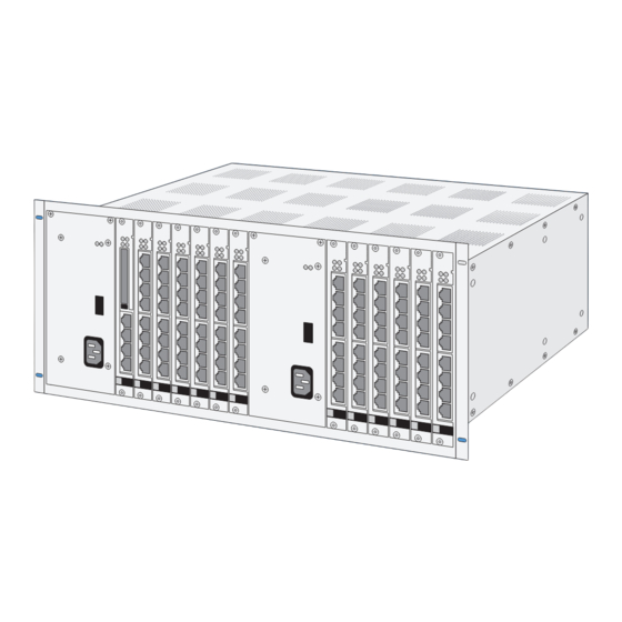
Construction of the OpenCom 510 Preliminary Information Construction of the OpenCom 510 The OpenCom 510 is designed to be used in 19" rack systems. It comprises the fol- lowing: ■ A 19" mounting frame for the modules. In a fully configured system, the fol- lowing modules will have been installed (and all slots will be occupied): 2 power supply units, 1 control module, 12 interface cards. -
Page 22: Declarations Of Conformity
– 1 CompactFlash Card; the firmware is stored on this card. This card is included in the scope of delivery only if the 1-12 frame is the first frame ordered and not being used to expand the OpenCom 510. All other components (e.g. second power supply unit, interface cards and accompanying cables) are included as per the customer’s order. -
Page 23: Installation
The MPS+1-AC power supply unit may not be opened as this may lead to exposure to hazardous voltage! Defective power supply units must be sent to the manufacturer for repairs. Always use the original packaging when packing OpenCom 510 components for transport or storage. CAUTIONT! Static charge can damage the OpenCom 510. -
Page 24: Notes On The Mains Supply
Always use a dedicated circuit with 10 A protection to supply the 19" frame (1- 12 frame). If the OpenCom 510 is being powered by two MPS+1-AC power supply units, each of the two units must be plugged into its own mains socket. It is not permissible... -
Page 25: Notes On Installing The Opencom 510
4.1.4 Notes on Installing the OpenCom 510 Do not allow any fluid to enter the OpenCom 510 as this may cause electric shocks or short circuits. Do not install the OpenCom 510 during a thunderstorm. Do not connect or dis- connect any cables during a thunderstorm. -
Page 26: Notes On Installing Terminals
OpenCom 510 to a Local Area Network (LAN). Installation, Ambient Conditions The ambient temperature for operating the OpenCom 510 must be between +5 °C and +40 °C. To maintain a safe ambient temperature, install the OpenCom 510 in a properly ventilated location, away from sources of direct heat. -
Page 27: Installation In A 19" Rack
Installation Installation in a 19" Rack If the OpenCom 510 is to be installed together with other electronic equipment in a 19” cabinet, ensure that the air intake temperature for the OpenCom 510 does not exceed +40 °C. The OpenCom 510 may also be connected to an IT system. -
Page 28: Installing Modules
Left and right screw points for earthing wrist strap or circuit common con- nection between 1-12 frame and 19" rack Note: If the OpenCom 510 is to be used as a wall-mounted instead of a floor-standing system, it must be installed in a standard-type wall-mounted enclosure using 19" mounting technology. -
Page 29: Slots
Installation Installing Modules 4.4.1 Slots The OpenCom 510 1-12 frame can house up to: ■ 2 power supply units ■ 1 control module ■ 12 interface cards (trunk or subscriber modules) split into 2 separate groups. The following slots are provided for installing these modules:... -
Page 30: Notes On Disconnecting The Mains Supply
If you unplug the mains cable of the group 1 (A) power supply unit, the OpenCom 510 ceases to be operational. However, slots 7 - 12 (D) will still be sup- plied with operating voltage. (Refer to the illustration OpenCom 510: 1-12 frame slots on page 26 to determine the location of the modules specified in parentheses above.) -
Page 31: Installing The Central Control Module
2. Wait until the LEDs of the installed modules start flashing red. DANGER! Hazardous voltages inside the device! 3. Unplug all of the mains cables of the OpenCom 510 to disconnect the system from the mains supply. The central control module must not be installed if the OpenCom 510 is switched on! Refer to Notes on Disconnecting the Mains Supply starting on page 28. - Page 32 Installing Modules 6. Carefully push the central control module into slot 0 (see also the illustration OpenCom 510: 1-12 frame slots on page 26). The printing on the front of the module should be at the top. Ensure that the backplane plug of the central control module is securely plugged into the socket on the backplane.
-
Page 33: Installing Interface Cards
Installation Installing Modules 4.4.4 Installing Interface Cards Interface cards can be installed or exchanged with the system powered up (“hot- plugging”). Proceed as follows: 1. If you want to exchange an interface card, the slot for this card needs to be deactivated first. - Page 34 Checking the Status of the Interface Cards via the Web Console You can also check the status of the interface cards via the Web console of the OpenCom 510. 1. Open the PBX Configuration: Ports: Slots page in the Configurator.
-
Page 35: Installing A Power Supply Unit
Installing Modules 4.4.5 Installing a Power Supply Unit Depending on the number of installed modules (interface cards), either one or two power supplies are required (see A and B in the illustration OpenCom 510: 1-12 frame slots on page 26): ■... -
Page 36: Backplane
7. Install further interface cards if required (see also Installing Interface Cards starting on page 31). 8. Switch the OpenCom 510 on. To do so, reconnect the power supply unit with the mains supply (if you are powering the OpenCom 510 with two power supply units, connect the second unit as well). - Page 37 Should you need to exchange the backplane, proceed as follows: DANGER! Hazardous voltages inside the device! 1. Unplug all of the mains cables of the OpenCom 510 to disconnect the system from the mains supply. Refer to Notes on Disconnecting the Mains Supply starting on page 28.
- Page 38 Configurator. This will reactivate the software packages. The backplane serial number is also used to encode the PARK of a DECT system. If you are using a DECT system with the OpenCom 510, you will need to re- enter the PARK.
-
Page 39: Uninterruptible Power Supply
UPS manufacturer as a reference. An MPS+1-AC power supply unit has a leakage current of < 0.5 mA. A 900-watt UPS is entirely sufficient to power the OpenCom 510. Power Failure In the event of a power failure, the system memory will retain all data (program and user data) without any changes. - Page 40 Testing the Power Failure Circuit You can test the configuration as follows: 1. Disconnect the OpenCom 510 from the mains supply (see instructions in Installing the Central Control Module starting on page 29, steps 1 to 3). 2. Disconnect the NTBA from the mains supply.
-
Page 41: Interfaces And Connectible Terminals
Terminals Overview The OpenCom 510 interfaces have been implemented as RJ45 sockets on the front of the interface cards and the central control module. No special proprietary cables are required. Patch panels can be connected by means of standard patch cables. -
Page 42: S Ports
Interfaces and Connectible Terminals Ports Overview: Interfaces and Connectible Terminals Interface Terminals/Systems Page (internal) ISDN terminals (DSS1 protocol): telephones, fax machines, base stations and handsets, ISDN cards for PCs Digital terminals (ISDN terminals, system telephones) and DECT base stations Analogue terminals: telephones, G3 fax machines, (external or internal) modems, external music-on-hold devices, external voice mail systems, external intercom systems... -
Page 43: Termination
Interfaces and Connectible Terminals Ports The following table explains the S interface pin assignment. Pin Number Assignment Not used Not used Send + Receive + Receive - Send - Not used Not used 5.2.1 Termination Each interface card has 16 DIP switches (S1 to S16, two per S interface). - Page 44 S interface cards must be activated. In a typical configuration, the OpenCom 510 will be connected to the network ter- mination for basic access (NTBA) with an externally switched S port; therefore, all terminating resistors of the interface card are activated in the default setting.
-
Page 45: External Isdn Ports (S External)
You can connect the OpenCom 510 to the NTBA or to a second OpenCom 510 for PBX cascading. To connect the OpenCom 510 to the NTBA, wire pins 3, 4, 5, 6 of the NTBA and of the OpenCom 510 1:1. -
Page 46: Internal S
Interfaces and Connectible Terminals Ports PBX 1, S 1 2 3 4 5 6 7 8 8 7 6 5 4 3 2 1 PBX 2, S (RJ-45 socket) Wiring for direct connection 5.2.3 Internal S Ports Up to eight ISDN terminals per bus can be connected to the internal S ports by means of four-wire cables. -
Page 47: Technical Information
Interfaces and Connectible Terminals Ports The (corded) OpenPhone 63 and OpenPhone 65 system telephones can be cascaded by means of a U adapter, which enables you to connect two Open- Phones to one U port. For further information, refer to the “OpenPhone 61, 63, 65”... -
Page 48: Dect Base Station Connection Variants
Interfaces and Connectible Terminals Ports 5.3.3 DECT Base Station Connection Variants A DECT base station can be connected to either one or two U interfaces: ■ If the DECT base station is connected to one U interface, four simultaneous calls or connections can be made through the handsets. ■... - Page 49 Interfaces and Connectible Terminals Ports Pin Number Assignment b *) Not used Not used *) If the DIP switches are set accordingly, the conductors of the adjacent U port will be connected here; use only the first U port in this configuration. Setting DIP Switches 1.
-
Page 50: A/B Ports
A suitable external device for music on hold is the Genius 2000, manufactured by Speech Design. If you are not using an external MoH device, the OpenCom 510 offers an internal MoH feature: You can change the MoH melody in the SYS Confi- guration: Components menu of the Configurator. - Page 51 Doorstation 2-wire under Type. Activate the Actuator option, if you want to use the actor port of the OpenCom 510 instead of the “DoorLine” relay. The “DoorLine” actor can be operated only when the speech channel is open at the same time.
-
Page 52: Technical Information
Interfaces and Connectible Terminals a/b Ports The intercom system should be installed by qualified personnel only as sensor/ actor contacts will need to be connected to the “DoorLine” module. 5.4.2 Technical Information The a/b ports have been implemented as RJ45 sockets. Each of the devices listed above can be connected to the a/b interface by means of a two-wire 1:1 cable. -
Page 53: Lan Port
OpenCom 510 into a company LAN (Local Area Network) with the use of a 10-Mbit hub or switch. In such a configuration, the OpenCom 510 can, for example, act as an IP router for establishing Internet connections. -
Page 54: Service Pc
Interfaces and Connectible Terminals COM Port 5.5.2 Service PC The Ethernet interface can also be used to connect a service PC using a crossed Ethernet cable. COM Port The COM port (V.24-1 interface) on the MC+1-3 central control module can be used to connect a PC for the purpose of transmitting connection data. - Page 55 Interfaces and Connectible Terminals COM Port Pin Number Assignment Not used...
-
Page 56: Accessories And Adapters
Accessories and Adapters Adapter Accessories and Adapters The OpenPhone 63 and OpenPhone 65 system telephones have one or two slots on the rear for various adapters and other accessories. Further information on installing and operating these add-ons can be found in the “OpenPhone 61, 63, 65”... -
Page 57: Audio Adapter
2 (peak): recording signal + and stopping recor- ding. 3 (ring): relay contact 1 Not used on Round power OpenCom 510 socket (4 mm) Door display RJ-11 or 4, 5: relay contact 2 RJ-12 1, 2, 3, 6: NC... -
Page 58: Approved Devices / Approved Accessories
Accessories and Adapters Approved Devices / Approved Accessories Electrical Data of Ports Port Connection Values Microphone, Electret microphone microphone of second handset, Typical sensitivity: 10 mV/Pa headset microphone Power feed: I < 300 µA at 1.5 V Ear cap, Typical impedance: 150 ± 30 ohms loudspeaker of second handset, Typical sensitivity: 94 dB/1 mW headset, headset loudspeaker... -
Page 59: Device Combinations
Accessories and Adapters Device Combinations The following devices are recommended: Type Manufacturer, Product Designation Microphone: Winfinity, 4511326 / H 282-18 Loudspeaker: Siemens, L30460-X1278-X Recording device: No recommendation Device Combinations You can use the following power values to calculate the power consumption of combined equipment: ■... - Page 60 Accessories and Adapters Device Combinations Configurations without Plug-in Power Supply (Range up to 500 m) The following table shows examples of equipment combinations for which the maximum power consumption of 2.4 W is not exceeded. Basic Unit: OpenPhone 63 Add-ons Second Terminal Power Audio...
- Page 61 Accessories and Adapters Device Combinations Configurations without Plug-in Power Supply (Range 500 to 1000 m) The following table shows examples of equipment combinations for which the maximum power consumption of 2.2 W is not exceeded. Basic Unit Add-ons Power Audio adapter Up to 3 key- adapter...
- Page 62 Accessories and Adapters Device Combinations Basic Unit: OpenPhone 65 Add-ons: Second terminal (OpenPhone, OP) Up to 3 Audio adap- OP 61 OP 63 OP 65 keypad adapter without without ter and modules adapter adapter and plug-in po- with 1 keypad wer supply module ●...
-
Page 63: Modules
Modules Modules This chapter provides detailed technical information on the modules which can be installed in the OpenCom 510. You will find information on their respective fields of application, along with technical and operational information and notes on indicators. The modules fulfil the following tasks: ■... -
Page 64: Module Naming Conventions
Modules Module Naming Conventions Module Naming Conventions Modules are named according to a schema which enables the deduction of the module’s type and function: Mx+y1-z Abbr. Meaning Module Indicates the module type as follows: Control Subscriber Trunk Subscriber/Trunk Power Supply Character used to divide the product name Indicates the interface type as follows: Analogue interface... -
Page 65: Overview Of Available Modules
Modules Overview of Available Modules Overview of Available Modules The following table provides an overview of modules available for the OpenCom 510: Name Description Page MPS+1-AC Power supply with AC/DC transformer MC+1-3 Central control module with three interfaces MT+S2M1-1 Trunk module with one S... - Page 66 Modules Overview of Available Modules MX+S01-8 Detail: Printing on the front of an MX+S01-8 interface card...
-
Page 67: Mps+1-Ac
MPS+1-AC Field of Application The MPS+1-AC power supply unit supplies power to the first six slots (1 to 6) of the OpenCom 510. It converts the (220 V/110 V) AC input voltage into DC voltage +3.3 V and 42 V. - Page 68 Modules MPS+1-AC Input Voltage Rated voltage 230 V via standard IEC connector Voltage range 95 V to 275 V Rated current 2.0 A at 115 V 1.0 A at 230 V 0.9 A at 275 V Efficiency at rated load >...
- Page 69 Modules MPS+1-AC ■ Right: If the right LED is constantly lit up green, the output voltage is –42 V. The LEDs only indicate that the voltage is present. They do not say anything about the voltage quality. Operational Information The MPS+1-AC power supply unit will be ready for operation as soon as it has been plugged into the designated slot (see Slots starting on page 27).
-
Page 70: Mc+1-3
MC+1-3: Front view Field of Application The MC+1-3 module is the central control module of the OpenCom 510. It can be installed in slot 0 only (at the left end in the 1-12 frame; see Slots starting on page 27). - Page 71 DeTeWe distributor or local retailer if you want to purchase one of these cards. ■ The Ethernet port (10/100 Mbits/s) can be used to connect the OpenCom 510 to the LAN. ■ The V.24-1 interface can be used to connect additional apparatus, e.g. a com- puter for analysing call charges.
- Page 72 Operational Information If you need to exchange the central control module, shut down the system first! The OpenCom 510 must be disconnected from the mains supply (see Installing the Central Control Module starting on page 29). Do not pull the CompactFlash card during operation as this may cause data to be...
- Page 73 Modules MC+1-3 ■ 6 DTMF transmitters ■ 10 DTMF receivers ■ 1 Music On Hold ■ 32 HDLC controllers for RAS, ISP and DECT data.
-
Page 74: Mt+S2M1-1
The MT+S2M1-1 interface card provides one ISDN S interface for connecting the OpenCom 510 either to a primary rate access or to a second PBX (ISDN point-to- point connection). The MT+S2M1-1 interface card can be installed in any of the slots (1 to 12) of the OpenCom 510 (see Slots starting on page 27). - Page 75 Modules MT+S2M1-1 ■ A maximum of four MT+S2M1-1 interface cards can be configured in the entire system. ■ No settings need to be made on the MT+S2M1-1 interface card. ■ The MT+S2M1-1 interface card runs on software acquired from the system. After the card has been installed it will automatically load the required software.
- Page 76 Modules MT+S2M1-1 Pin Number Assignment –42 V Not used Not used Indicators There are four LEDs on the front of the MT+S2M1-1 interface card. MT+S2M1-1 MT+S2M1-1: LEDs The LEDs indicate the following: LED 1: Constantly yellow At least one connection established through the interface card is active.
- Page 77 Modules MT+S2M1-1 Constantly red New software is being loaded onto the interface card. If the LED lights up red for an extended pe- riod of time, there may be a fault. LED 3: Constantly green The interface card is providing the system clock signal (indicated only in the master system and only on an interface card).
-
Page 78: Mx+S01-8
The MX+S01-8 interface card provides eight 8 S interfaces which can be used for either external connections, i.e. to connect the OpenCom 510 to a digital network (PSTN, Public Switch Telephony Network), or internal connections, i.e. to connect digital terminals (ISDN telephones, ISDN fax machines etc.) to the OpenCom 510. - Page 79 Modules MX+S01-8 Pin Assignment For information on the S interface pin assignment, refer to S0 Ports starting on page 40. Indicators There are four LEDs on the front of the MX+S01-8 interface card. MX+S01-8 MX+S01-8: LEDs The LEDs indicate the following: LED 1: Constantly yellow At least one connection established through the interface card is active.
- Page 80 Modules MX+S01-8 Operational Information The MX+S01-8 interface card can be exchanged during operation, i.e. without powering down the system. However, the slot must first be deactivated in the Configurator in the web console (see Installing Interface Cards starting on page 31). All three protocol layers can be individually configured as master or slave for each interface.
-
Page 81: Ms+Upn1-8
DECT base stations. The MS+UPN1-8 interface card can be installed in any of the slots (1 to 12) of the OpenCom 510 (see Slots starting on page 27). Technical Information ■... - Page 82 Modules MS+UPN1-8 MS+UPN1-8 MS+UPN1-8 The LEDs indicate the following: LED 1: Constantly yellow At least one connection established through the interface card is active. LED 2: Constantly green The interface card is operational; the slot has been activated (flickering is normal). Flashing yellow The interface card is ready, but the slot has not been activated or the interface card has not...
-
Page 83: Ms+Upn2-8
DECT base stations. The MS+UPN2-8 interface card can be installed in any of the slots (1 to 12) of the OpenCom 510 (see Slots starting on page 27). Technical Information ■ The MS+UPN2-8 interface card can also be installed in a slave system. - Page 84 Modules MS+UPN2-8 MS+UPN2-8 MS+UPN2-8: LEDs The LEDs indicate the following: LED 1: Constantly yellow At least one connection established through the interface card is active. LED 2: Constantly green The interface card is operational; the slot has been activated (flickering is normal). Flashing yellow The interface card is ready, but the slot has not been activated or the interface card has not...
-
Page 85: Ms+A1-8
The MS+A1-8 interface card provides eight analogue interfaces for connecting analogue terminals. The MS+A1-8 interface card can be installed in any of the slots (1 to 12) of the OpenCom 510 (see Slots starting on page 27). Technical Information ■... - Page 86 Modules MS+A1-8 MS+A1-8 MS+A1-8: LEDs The LEDs indicate the following: LED 1: Constantly yellow At least one connection established through the interface card is active. LED 2: Constantly green The interface card is operational; the slot has been activated (flickering is normal). Flashing yellow The interface card is ready, but the slot has not been activated or the interface card has not...
-
Page 87: Ms+A1-4
The MT+A1-4 provides interface card four analogue interfaces for connecting analogue trunk lines. The MT+A1-4 interface card can be installed in any of the slots (1 to 12) of the OpenCom 510 (see Slots starting on page 27). Technical Information ■... - Page 88 Modules MS+A1-4 MT+A1-4 MT+A1-4: LEDs The LEDs indicate the following: LED 1: Constantly yellow At least one connection established through the interface card is active. LED 2: Constantly green The interface card is operational; the slot has been activated (flickering is normal). Flashing yellow The interface card is ready, but the slot has not been activated or the interface card has not...
-
Page 89: Configuration
The OpenCom 510 Web console Using the Web console, you can: ■ perform the initial configuration of the OpenCom 510, ■ configure users of the OpenCom 510 and authorise them to use certain system services, ■ carry out further system maintenance, ■... -
Page 90: Brief Guide To Initial Configuration
For the initial configuration you can connect the PC to the OpenCom 510 via the Ethernet port. The TCP/IP network protocol is used to set up a connection via one of these ports. You can then open the Web console of the OpenCom 510 and call up the Configurator from there. - Page 91 Configuration Brief Guide to Initial Configuration Setting the IP address in Windows XP Tip: To find out the IP address of the Web console, enter the code *182 digit procedure on a connected system tele- phone. You can also view the net mask by entering the proce- *183 dure .
-
Page 92: Configuring The Opencom 510
If the configuration PC gets its IP address automatically from the OpenCom 510 or if the OpenCom 510 is entered as the domain name server, you can also start the Web console by entering the DNS name. The DNS name in the factory setting is host.domain. - Page 93 4. Confirm this by clicking on OK. This puts all connected terminals into the “Guest” user group with restricted user rights. In this way you prevent interna- tional external calls from the terminals, for example, while you are configuring the OpenCom 510 and the users. OpenCom 510: dialogue box for initial access...
-
Page 94: Loading The Online Help
Configuration Configuring the OpenCom 510 5. The software opens a dialogue for initial access. Determine an administrator password and enter it in this dialogue. Also fill in the other input fields. 6. Confirm your input with Apply. 7. Click on the Configurator button on the home page. -
Page 95: Preconfiguration
170. 8.2.7 Remote Configuration The OpenCom 510 configuration can also be altered or updated remotely by a cus- tomer service centre or authorised dealer. This requires activation of internal RAS access in the OpenCom 510 for the customer service centre/authorised dealer. - Page 96 Using remote configuration, all OpenCom 510 settings (with the exception of the system PIN) can be edited or updated. New software versions of the OpenCom 510 and the software for the connected system terminals and base stations can also be installed (see the SYS Configuration: Firmware menu in the Configurator).
-
Page 97: Codes For Ip Configuration
The IP configuration of the OpenCom 510 is performed on the Web console in the Configurator, in the NET Configuration: LAN menu. In the event that the IP configuration of the OpenCom 510 has to be changed and access via the Web console is not possible, you can also use a code digit procedure to change these basic settings. -
Page 98: Saving And Loading The Configuration
“0000”. 8.2.9 Saving and Loading the Configuration Configurations are saved in a file archive and can be loaded to the OpenCom 510 either locally from a connected configuration PC, or by remote configuration. The following configuration and customer data can be saved and loaded again: ■... -
Page 99: Loading Sw Updates
The terminal software is part of the OpenCom 510 software and is automatically loaded into the terminals via the OpenCom 510 if the software version in the ter- minal is different from the terminal software stored in the OpenCom 510. -
Page 100: Generating Your Own Moh Files
The MoH file must be coded with 8000 Hz, 8 bit mono in accordance with CCITT, A- Law. This coding is required for the OpenCom 510 and can be set in the “Sound Recorder” when you save the file under Format (CCITT, A-Law) and Attributes (8000 Hz, 8 bit mono). -
Page 101: Configuration Examples
(if the multi-company variant is acti- vated). In addition, the OpenCom 510 can be used as an Internet access server. RAS access can also be implemented using the OpenCom 510, which enables the integration of external staff in the LAN. -
Page 102: Introduction To Tcp/Ip
In a single LAN it is possible to use various protocols for the transmission of data. The connection between a workstation computer and the OpenCom 510 runs via the IP protocol (also named TCP/IP) used on the Internet. IP can be used together with other protocols (e.g. -
Page 103: Opencom 510 In A Serverless Lan
DNS, Internet) Ext. PC 1 PC 2 The OpenCom 510 in a serverless LAN In a serverless LAN, the OpenCom 510 takes over the IP configuration of the con- nected workstations. All IP settings necessary for the workstations are assigned by... -
Page 104: Dns Name Resolution
OpenCom 510 is not visible in the network environment. 9.3.2 Internet Access If access to an ISP has been configured on the OpenCom 510, the OpenCom 510 can be operated as an Internet access server without any additional configuration of the workstations. When you want to see a Web page, you simply type the URL (uniform resource locator;... -
Page 105: Ras Access
Internet as the domain name (“firm-open- com.co.uk” for example). 9.3.3 RAS Access You can establish a connection to the OpenCom 510 from an external PC via an ISDN card. The necessary IP settings are transmitted by the OpenCom 510 on establishment of the connection. -
Page 106: Opencom 510 In A Lan With An Ip-Enabled Server
In a LAN with an IP-enabled server, the latter is also responsible for DNS name resolution. If you want to start the Configurator by entering a DNS name, you must link this name on the server with the IP address used by the OpenCom 510. For further information, refer to the server documentation. -
Page 107: Internet Access
You will find details in the server documentation. 9.4.2 Internet Access You can also use the OpenCom 510 as an Internet access server in a LAN with an IP-enabled server. To do this, you must enter the OpenCom 510 IP address on the server as the default gateway. -
Page 108: Ras Access
In a LAN with an IP-enabled server you can also enable external computers to dial in via the OpenCom 510. To do this, you should coordinate with the network admi- nistrator the IP address space which can be assigned to an external computer dialling in, and enter it in the Configurator, NET Configuration: RAS: ISDN menu, under Address Range. -
Page 109: Branch Link
Branch Link You can use the OpenCom 510 to interlink two LANs via ISDN. To do this, you configure two OpenCom 510 systems so that they can dial in to each other. In order for this to work, the two LANs must be configured for different IP address ranges (subnetworks). -
Page 110: Useful Information On Internet Access
Useful Information on Internet Access 9.6.1 Costs The OpenCom 510 uses a router function to access the Internet, which means that it automatically establishes an Internet connection when required and terminates the connection after a certain period of time if no data are being transmitted. -
Page 111: E-Mail
OpenCom 510. These e-mail accounts are then checked at regular intervals. If there are new e-mails in an e-mail account, and the OpenCom 510 has been con- figured for this function, the user specified in the OpenCom 510 user account is notified of the new e-mail on his system terminal. - Page 112 ■ The protocol will function without TCP/UDP port numbers, e.g. ICMP or IGMP. The OpenCom 510 NAT has suitable processes for ensuring the functions of many important protocols affected by these rules. These are the protocols FTP (in “active” mode), CuSeeMe (“videoconferencing”), IRC (“chat”), ICMP errors (“trace- route”) and ICMP echo (“ping”).
-
Page 113: Voice Over Ip (Voip)
Integrating the two communication net- works into a single communications network can provide considerable savings. The OpenCom 510 gives users all the features of system telephony through its use of an IP-based protocol. The control of the data connections used makes it possible to define exactly the voice and service quality. -
Page 114: Fundamentals
Voice over IP (VoIP) Fundamentals ■ Using voice-data compression with compressing codecs, it is also possible to make multiple IP-based telephone calls simultaneously on a 64 kilobit/s ISDN line ■ Use of PC-supported system telephones (so-called “Softphones”) without extra hardware costs ■... -
Page 115: Latency And Packet Length
Voice over IP (VoIP) Fundamentals A modern Intranet normally offers enough performance reserves and reliability to make good-quality VoIP telephony possible. Specific components can also be optimised; for example by using a modern switch which evaluates the TOS byte of IP packets or by replacing unreliable connections. -
Page 116: Voice Quality
Voice over IP (VoIP) Fundamentals Required bandwidth (kilobit/s) with respect to Packet Length and Codec Packet G.711 (not G.729A G.723.1 G.723.1 Length (ms) compressed) c. 6.3 kilobit/s 6.3 kilobit/s 5.3 kilobit/s 33.6 30.4 28.3 31.09 29.2 Note: To ensure SIP compatiblility, the older system telepho- nes OpenPhone 63 IP and OpenPhone 65 IP does not sup- port the G.723 codec any more. - Page 117 Voice over IP (VoIP) Fundamentals ■ G.729A (Level 2): Reduction to approximately 8 kilobit/s. ■ G.723.1 6.3 (Level 3): Reduction to 6.3 kilobit/s. ■ G.723.1 5.3 (Level 3): Reduction to 5.3 kilobit/s. Unfavourable packet length selection may reduce voice quality. The duration of the recording and not the data packet’s byte count is relevant in making this selection: ■...
-
Page 118: Optimisation
Various IP-based protocols are used for system telephony via the Internet protocol (“IP”) (see also Start Procedure starting on page 125). Multiple TCP connections are made between an IP telephone and OpenCom 510 for the telephone’s start pro- cedure, registration and signalling. -
Page 119: Useful Services
3 VoIP terminals. The Media Gateway also takes over the routing function for external SIP connec- tions, making 8 external SIP connections possible. Using the OpenCom 510, the Media Gateway is provided using at least one MG+ETH1-1 interface card. -
Page 120: Mg+Eth1-1
The MG+ETH1-1 interface card provides 16 Media Gateway channels for VoIP. The MG+ETH1-1 interface card can be installed in any of the OpenCom 510’s slots (1 to 12, see also the chapter Slots starting on page 27). Up to four MG+ETH1-1 interface cards can be operated. - Page 121 Voice over IP (VoIP) Media Gateway (MGW) MG+ETH1-1 MG+ETH1-1: LEDs The LEDs have the following meaning: LED 1: Constantly yellow At least one call is being conducted via the in- terface card. LED 2: Constantly green The interface card is operational; the slot has been activated (flickering is normal).
-
Page 122: Sip Telephony
SIP Telephony The SIP Internet (Session Initiation Protocol) protocol provides you with a low-cost, standardised option for telephoning via the Internet. OpenCom 510 enables you to use external SIP telephone connections (SIP trunk lines). The PBX Configu- ration: Trunks: Route menu gives you the option of making an SIP connection on a normal ISDN line in case of bundle overflow, breakdown or over-occupancy. - Page 123 Firewall or NAT configuration of the Internet gateway product used. Do not use OpenCom 510 as an Internet gateway if the product used is to be compatible with SIP telephony. These products provide a “Full Cone NAT”...
-
Page 124: Voip System Telephones
Voice over IP (VoIP) VoIP System Telephones You can configure SIP connections in the Configurator on the pages PBX Configuration: SIP: Accounts and PBX Configuration: SIP: Provider. Enter the technical attributes of a specific SIP provider, such as the IP addresses for the registrar and the STUN server under Provider. -
Page 125: Voip System Telephone Configuration
TFTP IP protocols. After the power supply is assured, the device’s internal boot loader is started which controls the further start procedure. Standard operating procedure is to contact the OpenCom 510’s DHCP server so that the start procedure can be concluded without problems. To register a new... -
Page 126: Lan Dhcp Server
DHCP service program’s online help or handbook. The MAC address of all VoIP system telephones always begins with 00:30:42. 2. Configure a fixed IP address for the OpenCom 510. To do this, call up the Confi- gurator and open the NET Configuration: LAN page. Click on the Change... -
Page 127: Start Procedure
IP address configuration in IP address and Network mask. Confirm with Apply. 4. Configure the OpenCom 510’s DHCP server to assign IP addresses. To do this, call up the Configurator and open the NET Configuration: LAN: DHCP Server page. Click on the Change button. - Page 128 5. The VoIP system telephone creates a TCP connection to the supplied IP- address/port-number combination and sends a registration query. The OpenCom 510 checks the MAC address sent with the registration and confirms the registration request if the VoIP system telephone is listed in the menu PBX Configuration: Devices: VoIP Phones.
-
Page 129: Openphone Ipc
Voice over IP (VoIP) OpenPhone IPC munication system. You may also need to configure BOOTP, DHCP and TFTP servers for the VoIP system telephone. 10.5 OpenPhone IPC Besides the hardware VoIP system telephones, PC software for VoIP telephony can also be deployed. This software can be used with the operating systems Windows 98 SE/ME and Windows 2000/XP. -
Page 130: Installation
10.5.2 Configuration Analogue to the VoIP system telephones, the OpenPhone IPC creates multiple IP connections to the OpenCom 510. When you start the program for the first time, the Options dialogue is automatically opened. Here you must configure the fol- lowing values: 1. - Page 131 ID. Select a random device ID to secure telephone usage. The device ID can only be read on the Web console. The displayed menu texts and parts of the operations software are elements of the OpenPhone IPC installation, but they can be loaded from the OpenCom 510 via TFTP. where necessary...
-
Page 132: Dectnetip
OpenCom 510 Configurator in the PBX Configuration: Devices: DECT Phones menu. 11.1 Properties 11.1.1 DECT base stations DECT base stations can be connected to the OpenCom 510 via U accesses or via network (TCP/IP). These DECT base stations are available for the type of access selected: ■... -
Page 133: Features
One of the DECTnetIP base stations that is installed assumes coordination and configuration of the DECT-over-IP functions (DECTnetIP-Manager). Select a base station that has a dependable data link to the OpenCom 510. Go to the PBX Confi- guration: Devices: DECTnetIP page in the Configurator. Enter the MAC address of... -
Page 134: Dual Operation
OpenCom 510. 11.2.1 Dual operation Simultaneous operation of base stations via U access and base stations via Ethernet access is possible with the OpenCom 510. Transparent handovers, for example, are only possible when between DECT base stations using the same... -
Page 135: Synchronisation
DECT terminal automatically re-establishes a connection (roaming). Be sure to keep the PARK ID of your OpenCom 510 in mind. The PARK ID is dis- played under System Info: Versions in the Configurator. If the PARK ID starts with 31, there may be an attempt at a handover between DECT base stations using dif- ferent access technology. -
Page 136: Pbx Cascading
PBX installations. If you merely need a larger number of connections, it is easy to link a second PBX (PBX Cascading). If you want to operate the OpenCom 510 at several locations with different PBXs, this is possible by PBX Networking (see page 140). -
Page 137: Putting A Cascaded Pbx Into Operation
Putting a Cascaded PBX into Operation Proceed as follows to put a cascaded PBX system into operation: 1. If you want to cascade two OpenCom 510 PBXs, you will need to set the frame number using the DIP switches on the central control module. - Page 138 PBX Cascading Putting a Cascaded PBX into Operation MC+1-3: Top view 1. Mount the slave system frame above or below the master system. Connect a system telephone to the slave system for a later performance check. Use the 1 terminal of an existing MS+UPN1-8 oder MS+UPN2-8 interface card. 2.
-
Page 139: Notes
PBX Cascading Putting a Cascaded PBX into Operation Please note: If you change the type of slave system later on, the port set- tings that have been made will be deleted. The master system then initialises the slave system. This may involve transfer of firmware (operating software) from the master system to the slave system. -
Page 140: Licensing Information
A licence is required for certain additional OpenCom 510 program packages, for example for the internal voice-mail system called OpenVoice. The following information is for customers who have already obtained licences for an OpenCom 510 and would like to cascade or network their existing system with another OpenCom 510. PBX Networking... - Page 141 PBX Cascading Licensing Information Note: You will need the serial numbers of both infocom sys- tems for porting the activation keys. The serial numbers can be found in the Web console's Configurator, in the System Info: Versions menu.
-
Page 142: Pbx Networking
OpenCom 510 as a DECT server, for example. ■ To network the OpenCom 510 with an OpenCom 1000. In this way you can use the OpenCom 510 as a PBX for a branch office, for instance. -
Page 143: Connections
PBX Networking Connections 13.1 Connections Networking two or more TK systems means interconnecting them. The OpenCom 510 allows you to use the following connections: ■ ISDN trunk lines ■ ISDN point-to-point connections (Q.SIG) on external S ports or on the S port ■... -
Page 144: Master/Slave
PBX Networking Connections Note: All layers of the Q.SIG-IP protocol are symmetrical. The following are unnecessary: a Master/Slave setting, clock and synchronisation settings (please refer to Connection via Q.SIG.IP starting on page 145). 13.1.2 Master/Slave For an ISDN connection, it is possible to determine which PBX is the protocol master and which the protocol slave. -
Page 145: Types Of Point-To-Point Connections
If more than one port with the setting L1 Type = “Slave” is configured on an OpenCom 510 and the setting L1 sync possible has been activated, then one of the ports is automatically defined as the L1 clock source. The OpenCom 510 will automatically switch the clock source to another port configured as an L1 clock source (if a line fails, for example). -
Page 146: Connection Via An Active Transmission System
PBX Networking Types of Point-to-Point Connections ■ Use the RJ45 jacks on one of the external S ports for an S connection between two OpenCom 510s. PBX 1, S 1 2 3 4 5 6 7 8 8 7 6 5 4 3 2 1 PBX 2, S (RJ-45 socket) Wiring of a direct connection... -
Page 147: Connection Via Q.sig.ip
If you are operating a fast and continuous internet connection at two or more locations, you can establish the TK system networking via internet connection as well. The OpenCom 510 uses the Q.SIG protocol, for use with ISDN point-to-point connections and transports the protocol and voice data via IP connections. -
Page 148: Configuration
PBX Networking Configuration Note: Q.SIG-IP cannot be operated using a connection with NAT. 13.3 Configuration The possible configurations described below can be set up in the Web console using the PBX Configuration: Trunks menu. 13.3.1 Trunk groups This is a group of lines of the same type and direction. A line can only be assigned to one trunk group (bundle). -
Page 149: Routes
PBX Networking Configuration 13.3.2 Routes A route is a group of trunk groups enabling a connection in one direction. If the first trunk group of a route is fully utilized, the next trunk group is seized (“trunk group overflow”). One trunk group can also be used for different routes. In the above example, a route set up for PBX 1 allows a connection to PBX 2. - Page 150 A default entry in the numbering table makes it possible to seize a “default route” for all remaining unassigned numbers. In particular, this simplifies configuration of the OpenCom 510 as a subsidiary system: the only entry you assign to the default entry is the route to the host system...
-
Page 151: Technical Details
13.4 Technical Details A different PBX number must be set for each OpenCom 510 in a PBX network. This setting can be found in the Web console, in the menu PBX Configuration: System: Settings under the heading System linking. You can also set the maximum value for the transit counter there. -
Page 152: Team Functions
Team Functions Introduction 14. Team Functions 14.1 Introduction With the team functions you can manage your telephone communication tasks by assigning lines with separate call numbers to the keys of different terminals. The terminal users, or team members, can thus pick up one another’s calls or tele- phone each other using the configured keys. - Page 153 Team Functions Introduction For example, you can configure call protection if you do not want to be dis- turbed, or call diversion to another telephone. ■ Team key: As with a trunk key, a team key can be used to receive or make calls. However, this key cannot be used to change the settings for managing calls;...
-
Page 154: Team Configuration
14.1.2 Team Configuration You can create teams and program call keys in the Configurator of the OpenCom 510 (PBX Configuration: Groups and Ports: Upn menu). Call key 1 is preset as a trunk key on all system telephones. This setting can be changed by the system administrator. -
Page 155: Three-Member Team
Team Functions Examples of Use The secretary’s terminal also has the executive’s call number configured as a direct call number (DK 10: executive’s office). The secretary can therefore reach the exe- cutive and put through calls even if the executive has programmed a substitute. Line Busy Indication If a line is busy, e.g. -
Page 156: Unified Team
Team Functions Examples of Use Miller TrK 10: Miller TK 11: Johnson TK 12: Smith Johnson Trk 11: Johnson TK 10: Miller TK 12: Smith Smith TrK 12: Smith TK 10: Miller TK 11: Johnson Example: three-member team Line Seizure Each team member’s call number, e.g. - Page 157 Team Functions Examples of Use Each team member has one OpenPhone 63 system telephone with all call keys programmed as trunk keys. Miller TrK 10: Support 1 TrK 11: Support 2 TrK 12: Support 3 Johnson TrK 10: Support 1 TrK 11: Support 2 TrK 12: Support 3 Smith...
-
Page 158: Toggle Team
Team Functions Examples of Use 14.2.4 Toggle Team The toggle team described here illustrates how a large number of call numbers can be managed efficiently with the help of team functions. Each team member has one OpenPhone 65 system telephone with all call keys programmed as trunk and team keys. - Page 159 Team Functions Examples of Use On each telephone it is possible to toggle between the calls on individual lines, e.g. TrK 10 and TrK 11, by pressing the appropriate key (toggling). Every call on a trunk key can be transferred to any other party by means of the R key.
-
Page 160: Call Queue
If more than one telephone number with a queue is confi- gured on the telephone, the total number of entries are displayed. Calls in a queue are handled by the OpenCom 510 in the following order of pri- ority: instant connection, door calls, automatic recalls, VIP calls, then other internal and external calls. -
Page 161: Activation Of Queues
Note: As calling fax machines often operate with the “voice” service indicator (e.g. on analogue ports), you should assign ports for fax machines on the OpenCom 510 to a user group without a queue. Queues can be combined with the “forwarding,” “pickup” and “hunt group” func- tions, for example, in order to configure an enquiry station for an operator. -
Page 162: Pickup
Call Queue Examples of Use If a call is to be forwarded “After delay”, it enters the queue. If the call has not been answered before the delay period expires, it will be forwarded to the target ter- minal and can then be answered there. 15.1.3 Pickup The functions “Pickup”... - Page 163 Call Queue Examples of Use ■ Configure the OpenPhone 27 under PBX Configuration: Ports: DECT-PP and assign the OpenPhone 27 its own telephone number. Check in the OpenPhone 27. ■ Under PBX Configuration: Call Distribution: Incoming or PBX Configu- ration: Call Distribution: Incoming PTP route all incoming calls to the number of the OpenPhone 65 trunk key.
-
Page 164: Group Of Three Enquiry Stations
Call Queue Examples of Use mobile OpenPhone 27. New calls are signalled on the OpenPhone 65 or enter its queue. 15.2.2 Group of Three Enquiry Stations The enquiry stations switch all incoming calls. Incoming calls are administered in queues. Depending on the number of arriving calls, one to three enquiry stations in this group are manned. - Page 165 Call Queue Examples of Use ■ Program a function key with the function “Sign on/sign off from hunt group” Calls: Hunt group on the three system telephones (in the menu Incoming calls are signalled in parallel to all signed-on enquiry stations. If the enquiry stations are busy, the incoming call joins the queue on each of the ter- minals in the hunt group.
-
Page 166: Multi-Company Variant
The OpenCom 510 hardware and software are used equally by all the companies, however. It is possible to configure the OpenCom 510 for each company and define the extent to which the features of the system may be used. -
Page 167: Configuring The Multi-Company Variant
(see Allocating Routing Codes starting on page 167). 6. An exchange must be set up for each company so that the OpenCom 510 can correctly process statuses in which a call should be routed to the exchange (see Configuring the Company Exchange starting on page 168). -
Page 168: Configuring And Managing Companies
Trunks menu. 16.1.2 Configuring and Managing Companies Up to five companies can be configured in the OpenCom 510. By default, one company with the name “Company 1” is predefined. All configuration settings, e.g. in the user groups or in the trunk group configuration, apply to this predefined default company if not other company has been selected. -
Page 169: Assigning Trunk Groups/Sip Accounts
(the users) via the lines of a certain trunk group of the OpenCom 510, each of the available trunk groups must be assigned to one of the companies. This is necessary to be able to transfer incoming external calls to the correct company exchange in cases where the called internal subscriber cannot be reached (“Connection to Operator”), for... -
Page 170: Configuring The Company Exchange
16.2 Working with the Multi-Company Variant All the features of the OpenCom 510 which the users may already be familiar with from the single-company variant are available in the multi-company variant. These features can be used to the same extent and can be used in exactly the same way. -
Page 171: Making Calls Between Companies
Configurator in the Phone Book menu. The number of entries in a company telephone book is unrestricted. The OpenCom 510 can manage up to 2,000 entries in all telephone books (in the central, personal and company telephone books). -
Page 172: Configuring The Pc Software
Windows operating system by installing drivers and programmes. You can find the installation programmes required for this on the product CD that comes with the OpenCom 510. Proceed as follows to install extra software: 1. Log on under Windows NT or Windows 2000/XP as the administrator. - Page 173 Configuring the PC Software PC Offline Configuration 3. On the product CD, in the offline configurator installation directory, you will find ZIP archives for various TC-system types. Copy the desired ZIP archives to the installation directory. 4. End the installation with a function test. With a double-click on the newly created desktop icon, start the StartCenter program.
-
Page 174: Setting Up Tapi
With a TAPI (Telephony Application Programming Interface) you can operate a CTI application (computer telephony integration). Here, the CTI application uses the services of the OpenCom 510 with the help of the TAPI driver installed on a Windows PC. Many telephony functions, such as enquiry, toggling, three-party conference, pick- up, call protection and call forwarding can be controlled using appropriate TAPI- compatible software. - Page 175 In the CTI server box you must enter the DNS name or the IP address of the OpenCom 510. Using the […] button you can search for this in the LAN. In the boxes Username and Password you enter the user data of one of the users configured on the OpenCom 510.
-
Page 176: Setting Up Net Capi
With a CAPI driver (common application programming interface) Windows pro- grammes are able to access services and functions of an ISDN card. With a network-based CAPI, the OpenCom 510 allows the use of ISDN functions also by PCs in which no ISDN card is integrated. -
Page 177: Using The Systray Display
17.4 Using the Systray Display You can configure a systray display for the OpenCom 510 to appear in the infor- mation area of the Start bar of a workstation. This systray display constantly shows you whether a WAN, a RAS or a Branch connection via ISDN is active. It is also pos-... -
Page 178: Browser For Opencti And Openhotel
Browser for OpenCTI and OpenHotel You can simplify the daily use of the OpenCTI and OpenHotel Web applications using the Web browser especially adapted for the OpenCom 510. Each time the workstation is restarted, this browser program can automatically start and log you in. -
Page 179: Setting Up Video Telephony
Configuring the PC Software Setting up Video Telephony Installing the browser 1. Call up the start mask from the product CD (see Configuring the PC Software on page 170). 2. From the start mask, select Software: Install Browser for OpenCTI or Software: Install Browser for OpenHotel. -
Page 180: Synchronising The Pc Clock
PC with the time of the OpenCom 510. Requirements You must enter the time zone so that the OpenCom 510 can calculate the time of the internal clock back to the GMT (Greenwich Mean Time) required for SNTP: 1. -
Page 181: Address Queries Using Ldap
17.8 Address Queries using LDAP You can search the data of the central telephone book of the OpenCom 510 from a workstation in the LAN using LDAP (Lightweight Directory Access Protocol). When configuring an LDAP-enabled program, specify the IP address of the OpenCom 510 as the address of the LDAP server. - Page 182 Configuring the PC Software Address Queries using LDAP 5. In the Look in list, select the entry with the OpenCom 510 address. Enter a user in the Name input field, Administrator for example. Then click on Find now. The list of entries found should now display the address from the central tele- phone book.
-
Page 183: Configuration Guide
The Configuration Guide contains a series of flowcharts that will help you to plan the configuration of the OpenCom 510 and guide you through the necessary set- tings step by step, focusing on the network settings. The individual charts are sum- marised below: ■... -
Page 184: Overview
Configuration Guide Overview 18.1 Overview Ethernet network (LAN) exists? Cross-connected ethernet cable available? Connect the configuration Connect the configuration Connect the OpenCom and the PC to the OpenCom COM port. PC to the OpenCom LAN port. configuration PC to the network Generate the Dialup Networking Enable DHCP. -
Page 185: Pbx Ports
Configuration Guide PBX Ports 18.2 PBX Ports Set the access type (multiterminal Define the access type access and/or system access). Set the external S interfaces and Define the external enter the telephone numbers interfaces assigned by your network provider. Do you have ISDN terminals Set the internal S interfaces Define the internal S... -
Page 186: Lan
Configuration Guide 18.3 Do you have a computer network? Finished Assign a name Host name to the OpenCom. The OpenCom takes Do you have a DHCP DHCP the settings from server in your network? your DHCP server Ask your network administrator for the Activate the OpenCom OpenCom address range for the RAS accesses. -
Page 187: Wan Settings
Configuration Guide WAN Settings 18.4 WAN Settings Do you want to configure Select a provider Your own ISP a new Internet provider? from the list “SYS Configuration: System: Select one of the Country” = “German”? default providers in “NET Configuration: Enter your provider's WAN”. -
Page 188: Ras Settings
Configuration Guide RAS Settings 18.5 RAS Settings Have you made the network settings for the OpenCom ? NET Configuration: Configure the network - settings for the OpenCom. Configure the RAS access of the OpenCom. “NET Configuration: RAS” Status Activate the RAS access. Specify the telephone number for which Telephone number the RAS access should be configured. -
Page 189: Branch Settings
Configuration Guide Branch Settings 18.6 Branch Settings Have you made the network settings for the OpenCom? NET Configuration: Configure the network- settings for the OpenCom. Configure the LAN-LAN connection. Protocol Select between PPP and HDLC transparent. “NET Configuration: Branch” Telephone number local Enter the internal telephone number. -
Page 190: E-Mail Function
Configuration Guide E-mail Function 18.7 E-mail Function Have you made the network settings for the OpenCom? Configure the network settings NET Configuration: for the OpenCom. Do you want to use e-mail Internet from the Internet? NET Configuration: Configure your Internet access. Has an internal e-mail server been configured in your LAN? No e-mail use... -
Page 191: E-Mail Access
Configuration Guide E-mail Access 18.8 E-mail Access Do you have access to a mail server Mail server in your network or in the Internet? Configure your network/ NET Configuration: LAN Internet access. or WAN Do you have created mail account polls User accounts in the “User Manager: User accounts”? Set up user accounts in... -
Page 192: Frequently Asked Questions
OpenCom 510. Please note: Repairs to the OpenCom 510 should only be carried out by qualified personnel. The following LEDs indicate that the OpenCom 510 is ready for operation: Activity LED LAN LED +3,3 V... -
Page 193: Telephony
Further information can be found in the chapter Modules starting on page 61. If the OpenCom 510 has not restarted properly, reset the OpenCom 510 to its ori- ginal factory setting (refer to the chapter entitled Resetting the System Data starting on page 97). - Page 194 One of the features (e.g. call diversion) on one of the telephones cannot be used even though the feature has been configured in the Configurator of the OpenCom 510. Make sure the user configured for this telephone belongs to a user group that has access to this feature (Configurator, User Manager: User and User groups menus).
-
Page 195: Dect
Frequently Asked Questions DECT An ISDN telephone always rings, if another telephone on the S bus is being called. This case also requires configuring the MSN on the ISDN telephone (see above answer). It is not possible to configure Call Distribution: Outgoing for multi-terminal access. -
Page 196: Lan
Check the LEDs for the LAN functions of the OpenCom 510. To check whether there is a network connection with your OpenCom 510, enter the “ping IP address” command in “Run” in the Windows Start menu (e.g. ping 192.168.99.254). - Page 197 The network connection is functioning, but nothing is displayed in the brow- ser. Enter the complete IP address of the OpenCom 510 along with the protocol iden- tifier, for example http://192.168.99.254/. Check whether the browser has been configured for connection through a proxy server.
-
Page 198: Internet
With the OpenPhone 27, the Internet can be accessed either directly via the remote data transfer network or indirectly via RAS access on the OpenCom 510. For direct access you can directly dial any provider. Indirect access uses the routing function of the OpenCom 510, accompanied by the configured security features, for example. - Page 199 A SIP connection only passes unidirectional voice. What is the reason? You did not use the OpenCom 510 as internet router or the STUN server of the SIP provider is unavailable. You need to activate the SIP support at your internet router, such as “SIP-ALG”...
-
Page 200: Technical Data
Please observe the technical information regarding modules under Modules starting on page 61. Component Page 1-12 frame of the OpenCom 510 – BPV+1-12 backplane system: Supply voltages and system signals for up to 2 power supply units, 1 central control module and 12 interface cards –... - Page 201 Technical Data The following table provides an overview of the configuration limits for the OpenCom 510. These limits result from the combination of different interface cards. OpenCom 510: system configuration limits (single 19" frame) Interface card maximal Maximum num- Note...
- Page 202 Technical Data OpenCom 510: system configuration limits (single 19" frame) Interface card maximal Maximum num- Note (module) insertable ber of interfaces MS+A1-8 88 x a/b – with a single 19" frame (a total of 12 slots) one slot is required for the outside line –...
-
Page 203: Notes On Disposal
Notes on disposal 21. Notes on disposal In order to avoid any possible effects resulting from the disposal of electrical and electronic equipment containing substances damaging to the environment and human health, the European Parliament and Council directives ■ 2002/96/EC on waste electrical and electronic equipment (WEEE) and ■... -
Page 204: Index
Index Index Numerics Configuration 87 Initial configuration 87 Loading software updates 97 1-12 frame 19, 25 Preconfiguration 93 19" frame 19, 25 Remote configuration 93 Resetting the system data 97 Saving and loading the configuration 96 a/b adapter 54 System prerequisites 88 a/b ports 48 Configuration examples 99 Accessories 56... - Page 205 Index DNS 102, 104 MS+A1-8 83 DSL 51 MS+UPN1-8 79 DSL port 51 MS+UPN2-8 81 DSS1 141 MT+A1-4 and MT+A1-8 85 DTMF 117 MX+S01-8 76 Overview 39 PCM 134 S0 40, 44 S2M 72 E-mail 13 Upn 44 V.24 11 Internet Access 12 Factory settings 17...
- Page 206 Index MT+S2M1-1 72, 143 Multi-terminal access 9, 140 Music on Hold 48 Q.SIG 141 External devices 48 Generating own files 98 MX+S01-8 76 Remote configuration 93 Resetting system data 97 Routes 147 NET CAPI 174 NTBA 191 NTBBA 51 Numbering 147 S0 port 192 S0 ports 40 External 43...
- Page 207 Index Terminals Overview 39 Three-member team 153 Time After a power failure 37 Time zone 178 Toggle team 156 Troubleshooting 190 Trunk key 150 Unified team 154 Upn ports 44 Voice Mail 49...
- Page 208 Index Notes...
- Page 209 Index Notes...
- Page 210 Index Notes...
- Page 212 DeTeWe Systems GmbH • Zeughofstraße 1 • D-10997 Berlin • www.Aastra-DeTeWe.de As of June 2006 Subject to changes...
Need help?
Do you have a question about the OpenCom 510 and is the answer not in the manual?
Questions and answers