Table of Contents
Advertisement
Quick Links
Advertisement
Table of Contents

Related Manuals for TESTO 300 XXL


Summary of Contents for TESTO 300 XXL
- Page 1 300 XXL Instruction manual...
-
Page 3: Table Of Contents
Contents Page Contents..........................3 Preface ..........................7 Principal safety information ....................8 System description 9 Control unit ......................9 Device operation ....................10 Touchscreen (option) ....................11 Overview of the measuring system................12 Menu overview 14 Control unit with analyser box................14 Control unit......................15 Commissioning ......................16 Function menu and function bar................16 Status display of the LED (analyser box)..............17 Power supply ......................18 Power supply, analyser box/control unit ............18... - Page 4 Contents Page Differential pressure measurement with the control unit ..........26 Differential pressure measurement with the control unit ..........27 CO measurement with the control unit ..............28 Gas leak probe with control unit................29 Humidity measurement with the control unit............30 Velocity measurement with the control unit..............31 Volume measurement in a duct ..............32 Mean value ......................33 Volume flow measurement ................34...
- Page 5 Contents Page Pitot tube factor ....................60 Cross section ....................61 Offset factor ....................62 Info ........................62 Alarm limits......................63 Timer ........................63 Main menu Device for control unit ................64 Changing date/time ....................64 Setting the date ....................64 Setting the time ....................66 Auto off ........................66 Printer ........................67 Setting the contrast ..................67 Entering print text ....................67 Light........................68...
- Page 6 Contents Page Main menu Service for analyser box and control unit ............87 Operating values ....................87 Switching off CO/NO ....................88 Device data ......................89 Bus address......................89 Maintenance ........................90 Inserting new paper roll in printer ................90 Changing the battery pack ..................91 Control unit......................91 Analyser box....................91 Filter change ......................92 Condensation trap ....................92...
-
Page 7: Preface
Dear Testo customer, Your decision to buy the testo 300 XXL was an excellent choice. The testo 300 XXL is designed for flue gas analysis and all measurements in heating systems. Thousands of customers buy our high-quality products every year. There are at least 7 good reasons for this: 1) Our price/performance ratio is good. -
Page 8: Principal Safety Information
Principal safety information Disposing of batteries Use the device only in the operating and measuring ranges specified in “Technical data”. The end user is legally required to dispose of all used batteries in accordance with their country’s Use the device only under the conditions and for regulations. -
Page 9: System Description
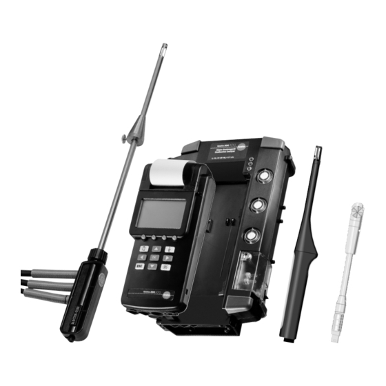
System description Control unit Printer Touchscreen pen holder Location Device active display Status display Reading window Reading display Touchscreen (option) on the rear: Contacts to analyser box Function bar Function keys Main menu display On/off button Acknowledgement Cursor keys Cancel/back Display lighting Mains adapter connection PC connection... -
Page 10: Device Operation
The display constantly shows all important information. The operation of the testo 300 XXL is designed so that the key functions are visible at all times on In the Reading/Menu display area, 6 readings the display. -
Page 11: Touchscreen (Option)
System description Touchscreen (option) Touch a position on the display with the special Measurement menu pen. The main menu appears. Each menu item can be accessed and activated with the special pen. The example shows the individual steps to set the lighting status of the control unit. Main menu P P e e r r i i p p h h e e r r y y Set automatic... -
Page 12: Overview Of The Measuring System
System description Overview of the measuring system Measuring cell heater protects against destruction by condensation Carrying handle LED status display Gas path filter Gas outlet 2 Fresh air inlet filter Fresh air inlet Contact strips to the control unit Diluting air filter Gas outlet 1 Condensation tank Flue gas probe... - Page 13 System description Overview of the measuring system Volume flow rate measurement with funnel Pressure measurement Integrated printer Temperature measuremen CO safety Display measurement Gas leak measurement Control unit /humidity 4 user-defined measurement RS 232 interface function keys Current measurement Voltage measurement Mains connection/ fast battery charge...
-
Page 14: Menu Overview
System description Menu overview Control unit with analyser box Duration M M a a i i n n m m e e n n u u No. values Read out Mean value Info Fuel meas. Save Duration Delete memory Delete Dilution MEMORY Free memory? -
Page 15: Control Unit
System description Menu overview Control unit Duration M M a a i i n n m m e e n n u u No./values Read out min input Info Mean MEMORY max input Save Delete memory min output Delete Free memory? max output Unit Decimal place... -
Page 16: Commissioning
Commissioning Function menu and function bar The function bar can be assigned as desired to all functions of the function menu. Pressing the key with a function key opens the function menu. The entries in the function menu change according to the connected components of the measuring system. -
Page 17: Status Display Of The Led (Analyser Box)
Commissioning Function menu and function bar Saves readings. M M e e m m . . T1 + T2, displays differential temperature. D D e e l l t t a a T T Differential pressure 0 - 80 mbar d d P P 1 1 Differential pressure 0 - 1000 mbar d d P P 2 2... -
Page 18: Power Supply
Commissioning Power supply Observe battery capacity. Ensure correct polarity. There should always be rechargeable batteries/batteries in the control unit. Power supply, analyser box/control unit AINS OPERATION Plug mains cable into analyser box. The power supply for the control unit is ensured when - control unit is connected to the analyser box by the contact strips - control unit is connected to the analyser box by the spiral... -
Page 19: Charging Batteries
Commissioning Battery charging Charging batteries, analyser box/control unit The battery packs must be installed in the analyser box and the control unit for charging. Plug mains cable into analyser box. Note The units must be switched off. Charging is impossible during operation. -
Page 20: Example Measurement
The temperature measured by the flue gas probe is interpreted by the testo 300 XXL as the combustion air temperature unless a AT probe is connected (Note: the probe must be removed from the flue). -
Page 21: Preparing For Measurements With The Control Unit And Analyser Box
Example measurement Preparing for measurement with the control unit and analyser box Note The analyser box does not need to be activated in the device selection menu. It is detected automatically when the measuring unit starts. Control unit + analyser box + flue gas probe Connect the flue gas probe before switching on the control unit and the analyser box. -
Page 22: Core Current Search With The Control Unit And Analyser Box
Example measurement Core current search with the control unit and analyser box Starting core current search: 1 Connect flue gas probe to analyser box. 2 Place flue gas probe in flue pipe. 3 Activate the function menu with the key and one of the function keys. -
Page 23: Flue Gas Measurement At Burners With Control Unit And Analyser Box
Example measurement Flue gas measurement at burners with the control unit and the analyser box Measurement menu Preparing for measurement 1 Specify new location and select (see page 41): Back to the measurement menu Location 2 The four function keys of the control unit are freely Measurement menu configurable with the functions of the function menu. -
Page 24: With The Control Unit And The Analyser Box
Example measurement Conducting a CO measurement in gas burners (flue gas path test) with the control unit and analyser box Function menu CO limit for the rejection of a system (in relation to undiluted flue gas): > 1000 ppm uCO 1 Activate the function menu with with the key and one of the function keys. -
Page 25: Draught Measurement With The Control Unit And Analyser Box
Example measurement Draught measurement with the control unit and the analyser box Measurement menu Preparing for measurement 1 sec Use the flue gas probe for the draught measurement. The draught measurement can be conducted before or after a flue gas measurement. Function menu A draught measurement is only possible with the pump switched off. -
Page 26: Differential Pressure Measurement With The Control Unit
Example measurement Differential pressure measurement with the control unit Preparing for measurement Measurement menu Selection of a suitable measuring range. 1 sec Two measuring ranges P1 (-80 to +80 hPa) and P2 (-1000 to +1000 hPa) are available in the function menu: Function menu Start measurement 1 Device selection: control unit... -
Page 27: Differential Pressure Measurement With The Control Unit
Before switching on the testo 300 XXL, connect the Measurement menu temperature probe! For pure temperature measurement, e.g. supply / return temperature The testo 300 XXL control unit has a multi-probe input. 1 sec 1 Activate the function menu with the key and one of Function menu the function keys. -
Page 28: Co Measurement With The Control Unit
Example measurement CO measurement with the control unit Connect probe before switching on the control unit! Cap must be closed during zeroing (measuring error otherwise possible). Open the cap only during the measurement, then replace. Measurement with: control unit + CO probe - Initialisation - Zeroing of the CO probe (60 sec) After zeroing, the CO probe is ready for measuring. -
Page 29: Gas Leak Probe With Control Unit
Example measurement Gas leak probe with control unit Do not use the gas leak probe and testo 300 XXL in enclosed rooms or facilities in which gases have accumulated into an explosive mixture. The use of other electrical equipment is also prohibited. -
Page 30: Humidity Measurement With The Control Unit
Example measurement Humidity measurement with the control unit Measurement with: combination humidity probe, e.g. Part no. 0636.9740 1 Connect combination humidity probe to the probe input of the control unit. 2 Switch on the control unit. 3 Current readings of relative humidity, temperature and dew point are displayed. -
Page 31: Velocity Measurement With The Control Unit
Example measurement Velocity measurement with the control unit Special notes on the thermal velocity probe with direction probe 0635.1041 Fully push down the cap of the probe. During the measurement, observe the markings of the probe head and on the telescope. The markings must form a line. -
Page 32: Volume Measurement In A Duct
Example measurement Velocity measurement (hot wire or vane) with the control unit Volume flow measurement in a duct with 500 mm diameter with velocity probe. 1 Connect the velocity probe to the probe input of the control unit. 2 Switch on control unit. 3 Activate the function menu with the key and one of the function keys. -
Page 33: Mean Value
Example measurement Velocity measurement (hot wire or vane) with the control unit Mean value 1 Connect the velocity probe to the probe input of the control unit. 2 Switch on control unit. 3 Activate the function menu with the key and one of the function keys. -
Page 34: Volume Flow Measurement
Example measurement Velocity measurement (volume velocity measurement with funnel) with the control unit Volume flow measurement at an inducing opening A volume flow rate funnel is required for volume flow rate measurement at an inducing opening (grid or cap with annular gap). -
Page 35: Velocity Measurement With The Pitot Tube
Note The pitot tube factor of the standard Testo pitot tubes is 1.00 and need not be changed. Enter the factor 0.67 for the straight testo pitot tubes. For other pitot tubes, ask the supplier for the pitot tube factor and store. -
Page 36: Co Measurement With The Control Unit
Example measurement measurement with the control unit Measurement with control unit + CO probe To avoid the effects of the CO2 content of respired air, hold the probe as far away from your body as possible. The measured CO2 value depends on the absolute atmospheric pressure. -
Page 37: Current/Voltage Measurement With The Control Unit
Example measurement Current/voltage measurement with the control unit Measurement with control unit + cable 0554.0007 Currents and voltages are measured with the probe 0554.0007. These signals can be assigned to a different physical unit. Example: 0...20 mA are to represent 0...100 %RH when displayed later. -
Page 38: Printing
Function menu 4 Press function key Print 5 Print. If no location is active, the printout is made with “NONAME”. Select print testo 300 XXL SN: 000321/D Smith Ltd. Manchester Memory identifier Location: furnace 5 Measurement menu 15:01:00... -
Page 39: Main Menu Memory (Analyser Box And Control Unit)
Main menu Memory Overview The memory organisation of the testo 300 XXL is designed such that a so-called “Location” must exist to identify a saved reading. This location can consist of up to 20 alphanumeric characters. For example, a location may be:... -
Page 40: Saving Without Selecting A Location
Main menu Memory Saving without selecting a location Depending on the selected devices, the readings are saved in the activated component (control unit or analyser box). Measurement menu If no location has been chosen after the device was switched on, data can still be saved. The location “NONAME”... -
Page 41: Creating A New Location
Main menu Memory Creating a new location Measurement menu 1. Change to menu “Location” with key 2. Press key in window “Location”. Change 3. With keys , select “New loc” and confirm with key 4. Enter the location. 5. With function key , the location is accepted in the Location “Location”... -
Page 42: Selecting Saved Location
. Returns to the measuring menu. 4. With the function key “Mem.” , the current readings are saved under the selected location. This menu item is accessible during the zeroing phase of the testo 300 XXL. Location saved location selected... -
Page 43: Using An Existing Location As Format For A New Location
Main menu Memory Using an existing location as format for a new location Measurement menu 1. Change to menu “Location” with key 2. Select the location to serve as the source for the copy. 3. Press Change 4. Activate the “copy” function. Press . -
Page 44: Changing Existing Location
Main menu Memory Changing existing location Measurement menu 1. Change to menu “Location” with key 2. Select the location to be changed. 3. Press Change 4. Activate the “Change” function. Press function key “OK”. 5. Press function key “ ” to the desired character. The last character is deleted each time. -
Page 45: Deleting Existing Location
Main menu Memory Deleting existing location Measurement menu 1. Change to menu “Location” with key 2. Select the location to be deleted. 3. Press change 4. Activate “Delete” function. Press function key 5. Location is deleted. Location 6. With function key or key back to the mea- surement menu. -
Page 46: Barcode Pen Overview
The location is automatically accepted in the location list of the testo 300 XXL and is selectzed as the active location. It is unnecessary to read or manually enter the customer number of the customer where you are measuring beforehand with a PC or by hand into the testo 300 XXL. -
Page 47: Reading A Location With The Barcode Pen
Main menu Memory Reading a location with the barcode pen (during the zeroing phase) Initialisation Device zeroing 10 sec Measurement menu You can also enter the location after the expiry of the zeroing phase. Reading a location from the measurement menu Measurement menu Measurement menu Reading several locations with the barcode pen from... -
Page 48: Displaying Saved Readings
Main menu Memory Displaying saved readings 1. Change to menu “Location” with key Measurement menu 2. Select location and confirm with key 3. Press key in the measurement menu. 4. Select “Memory” menu and confirm with key 5. Activate “Read out” menu with key Location 6. -
Page 49: Mean Calculation
Main menu Memory Mean calculation Measurement menu 1. Press in the measurement menu. 2. Select “Memory” menu and confirm via 3. Select mean value menu and press 4. Enter duration of mean calculation. Confirm reading by clicking on E E n n d d Main menu 5. -
Page 50: Printing Mean Calculation Result
Main memory Memory Printing mean calculation result Start 1. Start mean calculation Mean calculation 2. To measurement menu after automatic stop. 3. Change to “Main menu” menu by clicking on 4. Activate “Memory” menu. Automatic stop 3. Select “Read out” sub-menu. Measurement menu 4. -
Page 51: Deleting Entire Memory
Main menu Memory Deleting entire memory Measurement menu 1. Change to menu “Main menu” with key 2. Activate the “Memory” menu. 3. Select submenu “Delete memory”. 4. Delete memory “Yes/No” Main menu 5. Confirm with key 6. Return to measurement menu via Memory menu Select “Delete memory”... -
Page 52: Printing Saved Readings Of A Location
Main menu Memory Printing saved readings of a location 1. Change to menu “Location” with key 2. Select location and activate function key C C h h a a n n g g e e 3. Select menu “Print location”. Measurement menu 4. -
Page 53: Free Memory
Main menu Memory free memory? The menu provides information on the available memory Measurement menu capacity to save readings. 1. Change to the main menu with key Main menu 2. Activate the “Memory” menu with 3. Select “free memory?” 4. Display free memory with key Select “Memory”... -
Page 54: Main Menu Probe For Control Unit
Main menu Probe for control unit Scaling Measurement menu Currents and voltages are measured with the probe 0554.0007. These signals can be assigned to a different physical unit. Example: 0...20 mA are to represent 0...100 %RH when Select “Probe” displayed later. 1 Connect current and voltage cable, switch on control unit. -
Page 55: Resetting
Main menu Probe for control unit Measurement menu Resetting Entered scaling values are reset to the factory settings. 1. Change to the main menu with key Select “Probe” 2. Activate “Probe” menu with 3. Select “Reset”. 4. Display the probe socket with key 5. -
Page 56: Main Menu Input For Control Unit
Main menu Input for control unit Parameters Note The temperature, relative humidity and absolute pressure influence the air density at the measuring point. When these values have been entered, the density is calculated automatically. The result is composed as follows: Temperature Humidity Density... -
Page 57: Humidity
Main menu Input for control unit UMIDITY Measurement menu Enter the humidity as a parameter: 1 Connect probe, switch on control unit. 2 Change to the main menu with key 3 From Main menu – Input – Parameter – select Humidity menu. -
Page 58: Pressure
Main menu Input for control unit Measurement menu RESSURE Note The absolute pressure is determined in the measuring procedure depicted to the side. The absolute pressure results from • Altitude pressure (metres above sea level) This has an annual average at sea level of 1013 mbar. The higher the location is above sea level, the lower the pressure. -
Page 59: Density
Main menu Input for control unit Measurement menu ENSITY Note Factory setting: 1293 g/m If this value is not changed, this value is used for the calculation. The individual values are not taken into account. The temperature, relative humidity and absolute pressure Select “Input”... -
Page 60: Pitot Tube Factor
Measurement menu ITOT TUBE FACTOR Note The pitot tube factor of the standard Testo pitot tubes is 1.00 and need not be changed. Enter the factor 0.67 for the Select “Input” straight testo pitot tubes. For other pitot tubes, ask the supplier for the pitot tube factor and store. -
Page 61: Cross Section
Main menu Input for control unit Measurement menu ROSS SECTION Enter the cross section as a parameter: 1 Connect probe, switch on control unit. Select “Input” 2 Activate the function menu with the key and one of the function keys. Select the function key with Activate “Parameter”... -
Page 62: Offset Factor
Main menu Input for control unit Measurement menu FFSET FACTOR 1 Connect probe, switch on control unit. Select “Input” 2 Change to the main menu with key 3 From Main menu – Input – Parameter – select “Offset factor” menu. Activate “Parameter”... -
Page 63: Alarm Limits
Main menu Input for control unit Alarm limits Activate “Alarm limits” Note: The alarm for CO is factory adjusted and activated to 30 ppm and for CO2 to 5000 ppm. The alarm limits for dP are set to zero and deactivated. The acoustic alarm is switched If alarm limits are set and activated, a message appears on Select “Audible alarm”... -
Page 64: Main Menu Device For Control Unit
Main menu Device for control unit Measurement menu Changing the date ETTING THE DATE 1 Switch on control unit. 2 Change to the main menu with key 3 From Main menu – Device – Change date – Set date/time Main menu menu 4 Activate menu “Set date”... -
Page 65: Setting The Time
Main menu Device for control unit Measurement menu ETTING THE TIME 1 Switch on control unit. 2 Change to the main menu with key 3 From Main menu – Device – Change date – Set Date/time menu. 4 With key , select menu “Change date”... -
Page 66: Auto Off
Main menu Device for control unit Measurement menu Auto off The period after which the control unit switches off when not in use is specified in the menu “Auto off”. Main menu 1 Switch on control unit. Select “Device” 2 Change to the main menu with key 3 From Main menu –... -
Page 67: Printer
Main menu Device for control unit Printer Measurement menu ETTING THE CONTRAST Main menu 1 Switch on control unit. 2 Change to the main menu with key Select “Device” 3 From Main menu – Device - Printer - Contrast- Set contrast 4 This is accepted automatically with key E E n n d d Select “Printer”... -
Page 68: Light
Main menu Device for control unit Light Measurement menu Note “On/Off” Pressing key switches the lighting on, Main menu pressing again back off. “Automatic” Pressing key switches the lighting on, Select “Device” after approx. 3 min. the lighting is automatically switched off. -
Page 69: Units
Main menu Device for control unit Units Measurement menu Example: Set °C 1 Switch on the control unit. Main menu 2 Change to the main menu with key Select “Device” 3 From Main menu – Device - Units - Temperature - enter °C. -
Page 70: Main Menu Service For Control Unit
Main menu Service for control unit Operating values Measurement menu 1 Switch on control unit. 2 Change to the main menu with key Main menu 3 From Main menu - Service – select “Op. values”. Select “Service” 4 Return to the measurement menu with key Select “Op. -
Page 71: Language
Main menu Service for control unit Language Measurement menu 1 Switch on control unit. 2 Change to the main menu with key Main menu 3 From the main menu - Service - Lang. - Set language. Select “Service” 4 Return to the measurement menu with key Select “Language”... -
Page 72: Solid Fuel Measurement Option For Analyser Box
Solid fuel measurement option for analyser box The use of a probe preliminary filter is obligatory for measuring solid fuels: For 335mm probe: 0440 7435 Measurement menu For 700mm probe: 0440 7436 1 Connect analyser box and control unit; switch on control unit. -
Page 73: Co Measuring Ranges In Different Dilution Stages
Solid fuel measurement option for analyser box CO measuring ranges with CO Low or CO High CO meas. CO concentration Measuring range CO Accuracy range in sensor (ppm) (ppm) from..to from..to 1000 1000 See Technical data High 1500 1000 30000 ±... -
Page 74: Recalibration
Main menu Sensors for analyser box Measurement menu Sensors ECALIBRATION 1 Connect analyser box to control unit; switch on control unit. 2 Change to the main menu with key 3 From Main menu - Sensors – to menu “Recalibration” Select “Sensors” 4 With key , select the parameter and activate with key... -
Page 75: Print Cal. Data
Main menu Sensors for analyser box Measurement menu ADDITION 1 Connect analyser box to control unit; switch on control unit. 2 Change to the main menu with key 3 From Main menu – Sensors – to menu “NO2 addition” Select “Sensors” 4 With the cursor keys select numbers in the numeric block and confirm with key... -
Page 76: Main Menu Input For Analyser Box And Control Unit
Main menu Input for analyser box Measurement menu Spot number / Oil derivative / Heat carrier temperature Note: Enter spot number and oil drivatives only for oil fuels and propane. 1 Connect analyse box to control unit; switch on control unit. -
Page 77: Fuel
Main menu Input for analyser box Fuel Zeroing phase XAMPLE Set “Light oil” 1 Connect analyser box to control unit; switch on control 3 sec unit. “Select Light oil” 2 During the zeroing phase, the menu “Select fuel” is automatically activated. 3 Select “Light oil”... - Page 78 Main menu Input for analyser box Zeroing phase XAMPLE “Light oil” is selected. 1 Connect analyser box to control unit; switch on control unit. 2 During the zeroing phase, the menu “Select fuel” is 3 sec automatically activated. Select “Light oil” 3 Activate “Light oil”...
-
Page 79: Parameters
Main menu Input for analyser box Zeroing phase Parameters RESSURE Note The absolute pressure is determined in the measuring 3 sec procedure depicted to the side. The absolute pressure results from • Altitude pressure (metres above sea level) This has an annual average at sea level of 1013 mbar. The higher the location is above sea level, the lower the pressure. -
Page 80: Pitot Tube Factor
The pitot tube factor of the standard Testo pitot tubes equals 1.00 and need not be changed. Enter the factor 0.67 for the straight testo pitot tubes. For other pitot tubes, ask 3 sec the supplier for the pitot tube factor and store. -
Page 81: Cross Section
Main menu Input for analyser box Zeroing phase ROSS SECTION Enter the cross section as a parameter: 1 Connect the probe. Connect analyser box to control unit; 3 sec switch on control unit. 2 Change to the main menu with key 3 From Main menu –... -
Page 82: Offset Factor
Main menu Input for analyser box Measurement menu FFSET FACTOR 1 Connect probe, switch on control unit. Select input 2 Change to the main menu with key 3 From Main menu – Input – Parameter – select “Offset. factor” menu. Activate “Parameter”... -
Page 83: Info
Main menu Input for analyser box Zeroing phase Overview of all parameters. 1 Change to the main menu with key 3 sec 2 From Main menu – Input – Parameter – select the “Info” menu. 3 Return to the measurement menu with key Main menu Select “Parameter”... -
Page 84: Dew Point At
Main menu Input for analyser box Dew point/ambient air (AT) Zeroing phase 1 Connect humidity probe to control unit. Connect analyser box to control unit; switch on control unit. 3 sec 2 Change to the main menu with key 3 From Main menu – Input – Dew point/ambient air – select the “Temperature/ambient air”... -
Page 85: Main Menu Device For Analyser Box And Control Unit
Main menu Device for analyser box View Zeroing phase The display sequence of the readings is defined in this menu. The sequence can be freely selected. Example: 3 sec The first empty display box is occupied by the reading “Flue gas temperature”. -
Page 86: Diagnostic
Main menu Device for analyser box 8 Automatic branch to menu “Unit”. Find empty reading space Note If a parameter is selected, a matching unit is automatically presented. This suggestion can be changed. Assign empty reading 9 With key , the parameter is accepted. space 10 Return to the parameter menu with function key E E n n d d... -
Page 87: Main Menu Service For Analyser Box And Control Unit
Main menu Service for analyser box Operating values Zeroing phase 3 sec 1 Connect analyser box to control unit; switch on control unit. 2 Change to the main menu with key Main menu 3 From Main menu - Service – “Op. values” menu. 4 Return to the measurement menu with key Select “Service”... -
Page 88: Switching Off Co/No
Main menu Service for analyser box Switching off CO/NO/NO Zeroing phase 1 Connect analyser box to control unit; switch on control unit. 2 Change to the main menu with key 3 sec 3 From Main menu – Service – Switch-off. 4 With key , select menu “CO”, ”NO”... -
Page 89: Device Data
Main menu Service for analyser box Device data Zeroing phase 3 sec 1 Connect analyser box to control unit; switch on control unit. 2 Change to the main menu with key Main menu 3 From Main menu - Service – Device data menu 4 Return to the measurement menu with key Select “Service”... -
Page 90: Maintenance
Maintenance Inserting new paper roll in printer Measurement menu 1 Activate the function menu with the key and one of the function keys. Select the function key LF Pr with and confirm with 2 Open printer cover and remove plastic roller. 1 sec Function menu 3 Insert a suitable paper roll. -
Page 91: Changing The Battery Pack
Maintenance Changing the battery pack Control unit Rear 1 Pull off mains adapter. 2 Disengage catch. 3 Remove battery pack and pull plug from socket. 4 Insert new battery pack (adhere to marking on plug when inserting) 5 Put on and close cover. Analyser box Rear 1 Disconnect mains unit... -
Page 92: Filter Change
Maintenance Filter change Filter, flue gas 1. If the filter is visibly contaminated, it must be replaced under all circumstances. 2. Replace the filter if the pump performance drops (audibly). Filter, fresh In most cases, it is sufficient to replace the flue gas filter. air inlet - To replace a filter, remove the filter cover by twisting to the Filter, diluting air... -
Page 93: Flue Gas Probe
Maintenance Flue gas probe Cleaning the flue gas probe If the flue gas is heavily laden with dust, it is possible that sections of the gas path preceding the hose filter will become contaminated or blocked. Cleaning the flue gas probe with gas path closed Pull off the probe shaft, place and move about in hot water. -
Page 94: Changing O , Co And No Measuring Cells
Caution! The O2 measuring cell requires a compensation period of approx. 60 min. after replacement in the testo 300 XXL. Only then can accurate measure- ments be made. The device must not be switched on while doing this. Installation of CO / NO... -
Page 95: Maintenance Of The Gas Pumps
Maintenance Maintenance of the gas pumps Disconnect the mains plug prior to maintenance. Opening the analyser box 1. Switch off the device and pull the mains plug.. 2. Remove the condensation trap. 3. Unlock the three filter housings. 4. Loosen the 8 Philips screws in the lower part of the device housing. -
Page 96: Cleaning The Main Gas Pump With Optional Gas Preparation
Maintenance Maintenance of the gas pumps Cleaining the main gas pump with the gas preparation option Remove Philips screw from the plastic pump bracket. Push the plastic bracket gently aside. Pull the gas pump upwards out of the gas measuring block. -
Page 97: Changing The Pump Cassette Of The Condensation Pump With Optional Gas Preparation
Maintenance Changing the pump cassette of the condensation pump with optional gas preparation Empty the condensation trap. Remove the cover. Unlock and pull off the pump cassette. Remove the bend protection spring and push onto the hose of the inlet of the new pump cassette. Push on hoses. -
Page 98: Upgrades
Maintenance Upgrades Switch off the device. Open the measuring cell cover. Upgrade modules are connected at one of the empty slots. The measuring modules NO and HC must only be inserted at the slots marked “NO” and “Type A/HC” – observe switch settings. Connect the measuring modules NO , SO S at any desired slot marked... -
Page 99: Calculation Information
German calculation information The following equations were used to calculate the following values: x (21% - O : fuel-specific maximum 2max 2max value: value 21 % : oxygen content of the air in % : measured oxygen content in % : flue gas temperature Flue gas loss: qA = (FT-AT) - Page 100 UK calculation information Conversion of ppm to mg/m referred to the O reference value (freely selectable according to fuel) 2 set CO (mg/m CO = x CO (ppm) x 1.25 2 set Oxygen content in the air 2 set Measured oxygen content Fitted only 2 set NO-add...
- Page 101 UK calculation information (continued) Efficiencies x (FT - AT) X x (2488 + 2.1 x FT - 4.2 x AT) K1 x CO Effg=100- x 1000 + CO X = MH O+9H CO / CO ratio x (FT - AT) K1 x Q x CO X x (210 + 2.1 x FT - 4.2 x AT)
-
Page 102: Error Messages
Gas cooler not working Cell temperature Cell temperature outside too high specifications If we were unable to answer your question, please contact your distributor or Testo Cus- tomer Service. For contact data, see back of this document or web page www.testo.com/service-contact... -
Page 103: Technical Data
General technical data Storage and transport temperature ....-20...+50 °C Ambient temperature ..........-5...+45 °C Battery operation time ........approx. 7h (with pump running, lighting off) Analyser box testo 300 XXL Data memory: ............1 MByte Housing:................ABS Protection class:............IP20 Max. flue gas pressure: ..........50 hPa Flow rate of the internal pump: ....approx. - Page 104 Technical data Measuring range: ..........0...500 ppm Accuracy*: ..........±5 ppm (<100 ppm) ±5% of value (³100 ppm) :..............approx. 40 sec Resolution: ..............0.1 ppm Measuring range: ..........0..3000 ppm Accuracy: ..........±5 ppm (<100 ppm) ±5% of value (100... 2000 ppm) ±10% of value (>2000 ppm) :..............approx.
-
Page 105: Dimensions In Mm (L X W X H)
Resolution: ..............0.1 °C Control unit Storage and transport temperature ....-20...+50 °C Operating temperature........-5...+45 °C Power supply: ..........8V mains adapter Testo rechargeable battery Battery type AA Housing:................ABS Protection class:............IP20 Weight:................850 g Dimensions in mm (L x W x H): ....252 x 115 x 58 Display: ..........LCD graphic display... -
Page 106: Resolution
Technical data Pressure range 1 Meas. range ..........-80...+80 hPa Accuracy........±1% of value (-50...-80 hPa) ±0.5 hPa (-49.9...+49.9 hPa) ±1% of value (+50...+80 hPa) Resolution ........±0.01 hPa (-80...+80 hPa) Max. overload ............1200hPa Pressure range 2 Meas. range ..........-1000...+1000 hPa Accuracy......±2% of value (-200...-1000 hPa) ±4 hPa (-199,9...+199,9 hPa) ±2% of value (+200...+1000 hPa) Resolution ......±0.1 hPa (-1000...+1000 hPa) - Page 107 Technical data Current/voltage measurement Measuring range ..........0...20 mA Accuracy ..........±0.04 mA (0...20 mA) Resolution ..........±0.01 mA (0...20 mA) Humidity Resolution ........±0.01 % RH (0...100 % RH) Velocity (thermal) Measuring range: ..........0...+20 m/s Accuracy:........±0.01 m/s (0...-1.99 m/s) ±0.02 m/s (+2...+4.99 m/s) ±0.04 m/s (5...+20 m/s) Resolution ........±0.01 m/s (0...+20 m/s) Warranty...
-
Page 108: Ordering Data
Connecting cable control unit/PC 0409.0178 Trade Leak detection probe 0632.1246 Hose connection set, pressure 0554.0315 Analyser box Additional basic equipment, testo 300 XXL 0563.0352 Options for measuring box Precision draught measurement, 30 mbar 0440.3921 NO2 measuring cell 0440.3926 Gas preparation 0440.0355... - Page 109 0554.0555 measuring cell 0554.3926 Fresh air valve 0554.0557 Trigger input 0554.3932 IRDA upgrade (by testo service) 0554.0560 Solid fuel measurement CO (via testo service) 0554.0567 Spare parts / Consumables measuring module 0390.0070 CO/H measuring module 0390.0072 NO measuring module 0390.0074 measuring module 0390.0075...
- Page 110 Ordering data Connecting Measuring NiCr-Ni surface probe Order no. cable sec. range/accuracy 0604.0194 -200…+300 °C Very fast reacting surface probe with flexible 0614.0194* briefly up to +500 °C thermocouple band, rated length = 150 mm, Class 2 probe tip Ø 10 mm Very fast reacting surface probe with flexible -200…+300 °C Plug-on head...
- Page 111 Ordering data Connecting Measuring NiCr-Ni immersion/penetration probe Order no. sec. cable range/accuracy -200…+400 °C Fast-response immersion/penetration probe 0604.0293 Class 1 0614.0293* rated length = 150 mm, probe tip Ø 3 mm -200…+600 °C 0604.0493 Very fast-repsonse immersion/penetration probe for meas. in Plug-on head Class 1 0614.0493*...
- Page 112 Ordering data Connecting Pt100 immersion/penetration probe Measurement Order no. sec. cable range/accuracy Plug-on head -200…+400 °C Standard immersion/penetration probe 0604.0273 Order connecting Class A rated length = 200 mm, probe tip Ø 3 mm cable (page 56). Plug-on head Precision immersion/penetration probe -100…+400 °C 0628.0015* Order connecting...
- Page 113 Ordering data Connecting Meas. range Accuracy * Other probes Order no. cable for testo 950, 650, 400 sec. ±5 ppm (0…100 ppm) 0…500 ppm 0632.1247 CO probe ±5 % of value (r.o.r.) 50 ppm±2 % of 0…1 vol. % CO 0632.1240...
- Page 114 Ordering data Humidity/temperature probe for heavy industrial use Connecting Meas. range Accuracy * Order no. sec. cable ±2 %RH (2...98 %RH) Bar probe for 0…100 % RH <12 Plug-on head ±0.4 °C (0…50 °C) 0636.0340 humidity/temperature measurements in (probe tip) Order connecting cable ±0.5 °C (rest of range) -20…+70 °C...
- Page 115 Ordering data Connecting Cover caps for all humidity probes Ø 12 and 21 mm Order no. cable 0554.0665 Metal guard basket, material stainless steel V4A. Rapid compensation time, rugged and Ø 21 mm 0554.0755 heat resistant. Application: for flow velocities <10 m/s. Ø...
- Page 116 Ordering data Measuring method Meas. range Accuracy Order no. Pressure probes Pressure probe for measurement of flow ±0.03 hPa ±10 hPa***** 0638.1445 Differential pressure velocities and differential pressure ±0.1 hPa (0…20 hPa) ±100 hPa*** Differential pressure 0638.1545 ±0.5 % of value (rest) 2000 hPa*** 0638.1645 Absolute pressure...
- Page 117 Ordering data Velocity probes with handle/telescope Meas. range Accuracy Order no. for testo 400 0…10 m/s: 0…10 m/s 0635.1549 Economical, rugged hot ball probe for measurements in the low flow rate ± (0.03 m/s +5 % of value) -20…+70 °C (see note) range.
- Page 118 Notes...
- Page 119 Notes...
- Page 120 0970 3003 en 02 en-GB...
Need help?
Do you have a question about the 300 XXL and is the answer not in the manual?
Questions and answers