TESTO 350 Instruction Manual
Combustion & emission analyzer
Hide thumbs
Also See for 350:
- Instruction manual (107 pages) ,
- Short manual (28 pages) ,
- Instruction manual (104 pages)

Subscribe to Our Youtube Channel
Related Manuals for TESTO 350


Summary of Contents for TESTO 350
- Page 1 350 · Combustion & Emission Analyzer Instruction manual 1.800.561.8187 information@itm.com www. .com...
- Page 2 1.800.561.8187 information@itm.com www. .com...
-
Page 3: Table Of Contents
Contents Contents ....................3 Safety and the environment..............7 2.1. About this document ................7 2.2. Ensure safety...................8 2.3. Protecting the environment..............9 Specifications ..................10 3.1. Use ....................10 3.2. Technical data ................10 3.2.1. Examinations and licenses................10 3.2.2. Bluetooth module (option)................10 3.2.3. Declaration of Conformity ................12 3.2.4. - Page 4 First steps....................31 5.1. Commissioning ................31 5.2. Getting to know the analyzer............31 5.2.1. Power supply, batteries/rechargeable batteries ..........31 5.2.1.1. Recharging the rech. batt. of the Control unit ........31 5.2.1.2. Charging the rech. batt. of the analyzer box ........32 5.2.1.3.
- Page 5 6.1.3. Fuels & Test option ..................59 6.1.4. Sensor settings ....................59 6.1.4.1. NO addition ..................60 6.1.4.2. CxHy-Sensor ...................60 6.1.4.3. Sensor protection ................61 6.1.4.4. Calibration / adjustment ..............61 6.1.4.5. ppmh counter ..................64 6.1.4.6. Calibration data ................65 6.1.4.7. Negative value.................65 6.1.5. Programs .......................66 6.2.
- Page 6 Tips and assistance ................96 8.1. Questions and answers ..............96 8.2. Accessories and spare parts............98 8.3. Updating the instrument software ..........101 Appendix....................104 1.800.561.8187 information@itm.com www. .com...
-
Page 7: Safety And The Environment
Safety and the environment 2.1. About this document This document describes the product testo 350 with the device setting Country version > Please read this documentation carefully and familiarize yourself with the analyzer before putting it to use. Pay particular attention to the safety instructions and warning advice in order to prevent injuries and damage to the products. -
Page 8: Ensure Safety
Use only original spare parts from testo. > Any additional service must only be carried out by authorized personnel. Testo will otherwise refuse to accept responsibility for the proper functioning of the analyzer after repair and for the validity of certifications. -
Page 9: Protecting The Environment
> Operate the product only as described in this documentation. > Please consult your testo dealer or the manufacturer when in doubt. For products with Bluetooth (optional) Changes or modifications that have been made without the explicit consent of the responsible approval authority, may cause the retraction of the type approval. -
Page 10: Specifications
Specifications 3.1. The testo 350 is a portable combustion & emission analyzer. The instrument consists of the control unit (control unit for displaying readings and controlling the analyzer box) and the analyzer box (measuring instrument). - Page 11 The FCC demands that the user is to be informed that with any changes and modifications to the device, which have not been explicitly approved by testo AG, the right of the user to use this device will become null and void.
-
Page 12: Declaration Of Conformity
3.2.3. Declaration of Conformity 1.800.561.8187 information@itm.com www. .com... -
Page 13: Measurement Ranges And Resolution
3.2.4. Measurement ranges and resolution Analysis box Measurement Measurement Resolution parameter range 0…25vol.% 0.01vol.% CO, H -comp. 0…10000ppm 1ppm -comp. 0...500ppm 0.1ppm 0...4000ppm 1ppm 0...300ppm 0.1ppm 0...500ppm 0.1ppm 0...5000ppm 1ppm 0...300ppm 0.1ppm -(IR) 0...50vol.% 0.01Vol.% (0…25Vol.%) 0.1Vol.% (> 25Vol.%) 1, 2 Natural gas: 100…40000ppm 10ppm... -
Page 14: Accuracy And Response Time
Measurement Measurement Resolution parameter range Abs. Press., -240 to 461 "H 0.4 "H optionally when IR sensor is installed Flow velocity 0 to 131 ft/sec 0.1 ft/sec to 131 ft/sec Type K (NiCr-Ni) -328° to 2498 °F 32.18 °F Type S (Pt10Rh-Pt) 0° to 3200 °F 33.8 °F 3.2.5. - Page 15 Measurement Accuracy Response parameter time -(IR) ±0.3Vol.% ±1% of reading < 10s (t90) (0…25Vol.%) heat-up time: < 15min ±0.5Vol.% ±1.5% of reading (rest of range) ±400ppm (100…4000ppm) < 40s (t90) ±10% of reading (rest of range) Differential ±1.5% of fmv (-16 to -1 "H pressure 1 ±1.5% of reading (rest of range) Differential...
-
Page 16: Measurement Range Extension For Individual Slot (Option)
3.2.6. Measurement range extension for individual slot (option) Measurement Max. measuring Accuracy Resolution parameter range with highest dilution factor CO, H -comp. 0…400000ppm ±2% of reading 1 ppm 0…20000ppm ±2% of reading 0.1ppm -comp. 0…200000ppm ±2% of reading 1 ppm 0…12000ppm ±2% of reading 0.1ppm 0…160000ppm... -
Page 17: Other Instrument Data
500…2500ppm ±5% "H (-40 to 0 "H O at probe tip) 500…25000ppm ±5% "H (-40 to 0 "H O at probe tip) 300…1500ppm ±5% "H (-40 to 0 "H O at probe tip) 1500…20000ppm ±5% "H (-40 to 0 "H O at probe tip) 200…1500ppm ±5% "H... - Page 18 12 months sensor 18 months -(IR) sensor: 24 months Flue gas probe: 24 months Thermocouple: 12 months Rech. battery: 12 months Terms of warranty Terms of warranty: see website www.testo.com/warranty Control unit Feature Values Power supply • Li-ion rech. batt. •...
- Page 19 Feature Values Battery charge time <6hr Battery operation 2.5hr (with gas cooler and IR module) / time 4.5hr (without gas cooler and IR module) Dimensions 12.99 x 5.03 x 17.24 in. Housing ABS URL 94V0 Weight 10.58 lbs. (completely assembled) Memory 250000 readings Flue gas...
-
Page 20: Product Description
Product description 4.1. Control unit 4.1.1. Overview 1 IrDA interface 2 Switch On / Off 1.800.561.8187 information@itm.com www. .com... -
Page 21: Keyboard
> Keep a safe distance from products which could be damaged by magnets (i.e. monitors, computers, pacemakers, credit cards). 4 Display 5 Keyboard 6 Electrical contact bar for analyzer box (on rear) 7 Interfaces: USB 2.0, charger, testo data bus 4.1.2. Keyboard Functions Switch measuring instrument on/off [OK]... -
Page 22: Display
4.1.3. Display 1 Status bar (dark grey background): • Display of date and time (valid for control unit and analyzer box). • Display of Bluetooth status, power supply and remaining rech. batt. capacity (valid for control unit): Icon Feature Blue background/white symbol = Bluetooth on, Bluetooth connection to measuring box set up Grey background/white symbol = Bluetooth off Blue background/green symbol = Bluetooth... -
Page 23: Connections/Interfaces
4 Function display for function keys. 4.1.4. Connections / interfaces 1 USB 2.0 2 Testo data bus 3 Connecting socket for power supply 0554 1096 4 Guide groove for locking with analyzer box 1.800.561.8187 information@itm.com www. -
Page 24: Menu Guidance For Control Unit
4.1.5. Menu guidance for control unit Main menu Menu Description Saved measurements Display of saved measurements Device settings Date/Time Set date, time, time format: Power Options Automatic instrument shut-down on/off Display backlight in battery operation on/off Display brightness Set display brightness Printer Select printer, enter print text... -
Page 25: Analyzer Box
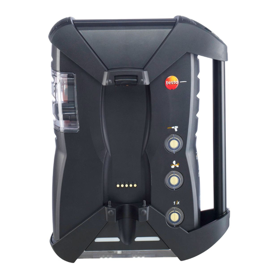
4.2. Analyzer box 4.2.1. Overview 1.800.561.8187 information@itm.com www. .com... -
Page 26: Status Display
1 Condensate trap and condensate container, 2 Locking/unlocking button for control unit 3 Particle filter 4 Filter fresh air inlet (option: fresh air valve/measurement range extension overall (5x)) 5 Contact bar for connection to control unit 6 Guide pins for locking with control unit 7... -
Page 27: Connections/Interfaces
9 DC-voltage input 11…40V DC (option) 10 Covering cap gas channel access (only for servicing purposes) Plugged in covering cap: Position ( ) must not be changed! 11 Pressure ports p+ and p- 12 Testo Data bus 1.800.561.8187 information@itm.com www. .com... -
Page 28: Functions/Instrument Options
4.2.4. Functions/instrument options Some functions are available as optional extras. The functions your analyzer box is equipped with (condition as delivered) is shown on the identification plate on the bottom side of the analyzer box. Imprint Description CO, NO, NO , SO The sensor of the specified type is check , CO... - Page 29 Main menu Menu Description Device settings Dilution Set the dilution factor Measurement view Configure the display, set measurement parameters and units for selected application and measurement type Units Set units for display variables Date / time Set date, time, time format: Power Options Set automatic instrument shut-down and switch off...
-
Page 30: Modular Flue Gas Probe
4.2.6. Modular flue gas probe 1 Removable filter chamber with window and particle filter 2 Probe handle 3 Connecting cable 4 Connector plug for measuring instrument 5 Probe module lock release 6 Probe module 1.800.561.8187 information@itm.com www. .com... -
Page 31: First Steps
32 to 122 °F. If the rech. batt. had been completely discharged, the charging time at room temperature will take about 7hr (charging with power supply adapter) or approx. 14hr (charging via testo Data bus). Charging via power supply (Art.-No. 0554 1096) ✓... -
Page 32: Charging The Rech. Batt. Of The Analyzer Box
Charging via analyzer box ✓ Control unit is locked to analyzer box or is connected via the testo data bus cable. ✓ The analyzer box is supplied via the power supply. During operation with low charge power or in switched off state. -
Page 33: Connecting Probes / Sensors
Control unit 1. Connect the plug of the power supply to the power supply socket on the control unit. 2. Connect the plug of the power supply to an electiric socket. The control unit is powered by the power supply. If the control unit is switched off the rech. -
Page 34: Occupying The Trigger Input
5.2.3. Occupying the trigger input The trigger input can be used as a criterion to either start or stop (ascending or descending flank) measuring programs. > Activating the trigger input, with external voltage supply (5...12 V): > Activating the trigger input, with supply via instrument voltage (12 V): When using the instrument voltage the analyzer can only be started via the trigger input from the switched off state... -
Page 35: Connection Using A Data Bus Cable (Accessory Part To A Bus System)35
Connection using a data bus cable (accessory part to a bus system) If testo easyEmission software is connected via a control unit to measuring boxes, the number of measuring boxes must not be changed. To add new measuring boxes, end... - Page 36 → [OK] → Data bus → [OK]. Bus address The bus address of each component connected to the testo data bus must be unambiguous. The bus address of the connected component can be changed, if necessary. 1. Bus Address →...
- Page 37 > Connect the data bus cable to the data bus interfaces. Please observe the following points when setting up a connection via data bus cable: • Use only testo data bus cables • Do not route data bus cables in the vicinity of electric power cables.
-
Page 38: Connection Via Bluetooth (Option)
Electrical termination of the bus system The data bus system is linear in structure. The control unit or the testo data bus controller with USB connection represents the beginning of the line. The end is represented by the last components connected in the system (analyzer box or analog output box). -
Page 39: Switching On
Via Bluetooth the control unit can be connected to a analyzer box or a PC/Notebook, as long as both components are equipped with this function, see Bluetooth, page 55. 5.2.5. Switching on Before switching on > Connect all system components. >... -
Page 40: Calling Up A Function
5.2.6. Calling up a function 1. Select function: [▲], [▼]. The chosen function appears in a frame. 2. Confirm selection: [OK]. The chosen function is opened. 5.2.7. Entering values Some functions require values (numbers, units, characters) to be entered. Depending on the function that is chosen, the values are entered via either a list field or an input editor. - Page 41 Input editor 1. Select the value to be changed (character): [▲], [▼], [◄], [►]. 2. Accept value: [OK]. Options: > Toggle between characters and special characters: ← → → → Select Ι &$/ Ι: [▲], [▼] → [ABC &$/]. > Position the cursor in the text: ←...
-
Page 42: Printing / Saving Data
(only available via Control unit tab) > → Search for boxes → [OK]. Analyzer boxes connected via testo data bus: are displayed (tabs) Analyzer boxes connected via Bluetooth: • Analyzer box found: Analyzer box and control unit are connected automatically •... -
Page 43: Switching Off
5.2.11. Switching off Unsaved readings will be lost when the analyzer is switched off. Rinse phase When switched off, the analyzer box checks whether flue gases are still in the sensors. The sensors are rinsed with fresh air, if this should be necessary. - Page 44 Creating a new measurement site: A measurement site is always created in a folder. 1. Select the folder in which the measurement site is to be created. 2. [Options] → New measurement site→ [OK]. 3. Enter values or make settings. The following inputs/settings are possible: Parameter Description...
- Page 45 Parameter Description Barometric The input of the barometric pressure and pressure the height above sea level is only required when no absolute pressure is available (no CO IR module present). The barometric pressure influences the calculation of flow speed, volume flow, mass flow and flue gas dew point.
-
Page 46: Saved Measurements
Other folder options: • Edit Folder: Make changes to an existing folder. • Copy Folder: Make a copy of an existing folder. • Delete Folder: Delete an existing folder, including the measurement sites created therein. • Delete All Folders: Delete all existing folders, including the measurement sites created therein. -
Page 47: Instrument Diagnosis
Display record: 1. Choose the desired record from the detailed view. 2. [Data]. Options > [Options] → [Delete All Measurements]: The readings of all measurement sites will be deleted. > [Options] → [Copy All Measurements]: The readings of all measurement sites will be copied. Analyzer box options >... -
Page 48: Error Diagnosis
5.5.1. Error diagnosis > Error diagnosis → [OK]. Unrectified errors, warnings and notes are displayed. > View next / previous error: [▲], [▼]. 5.5.2. Gas path check (only available via Analyzer Box tab) Check the analyzer regularly for leaks, to ensure accurate measurements. -
Page 49: Using The Analyzer
Using the analyzer 6.1. Settings 6.1.1. Assigning the right hand function key The right function key can have a function from the Options menu assigned to it. The menu Options is accessed via the left function key and is available in many different menus. This assignment is only valid for the currently opened menu / the opened function. - Page 50 Factor Ratio of diluting gas: Measuring gas no dilution 1 : 1 4 : 1 x 10 9 : 1 x 20 19 : 1 x 40 39 : 1 Auto dilution 4 : 1 If the dilution stage auto-dilution is selected, dilution (5x) is activated automatically when the set switch-off threshold of the sensor in slot 6 is reached.
-
Page 51: Measurement View
It is possible to calibrate/adjust with test gas when dilution is switched on to eliminate any measuring errors caused by dilution (see Calibration/adjustment page 61). Calling up the function: > → Device settings → [OK] → Dilution → [OK] 1. Select to dilute all (x5): →... - Page 52 Display Measurement parameter COamb Ambient carbon monoxide Nitrogen monoxide Nitrogen dioxide Nitrogen oxide Sulphur dioxide Hydrogen sulphide CxHy Hydrocarbon Hydrogen ExAir Air ratio Corrected carbon monoxide value Corrected sulphur dioxide value Carbon dioxide IR active Flow velocity Volume flow Volume flow DewPt Flue gas dew point temperature Mass flow CO...
-
Page 53: Units
Change parameter / unit in a line: 1. Select the line: [▲], [▼] → [Change] 2. S elect the parameter: [▲], [▼] → [OK] 3. Select the unit: [▲], [▼] → [OK] 4. Save changes: [OK] Options: > [Options] →... -
Page 54: Date/Time
6.1.2.4. Date/time This function is available in both the analyzer box and the control unit. Changes are accepted for the control unit and for the analyzer box. Date, time mode and time can be set. Activating the function: > → Device Settings →... -
Page 55: Printer
6.1.2.7. Printer This function is available in both the analyzer box and the control unit. This function is available for both the control unit and the analyzer box. The headers (lines 1-3) and the footer for the printout can be set. The printer that is used can be activated. -
Page 56: Language
Information concerning assignment table, basis of calculation and country version see www.testo.com/download-center (registration required). If several components with different country versions are connected, the components will automatically change to the country version of the control unit when the control unit is connected. -
Page 57: Password Protection
Activating the function: > → Device settings → [OK] → Country Version → [OK] This action can be password protected. A password is specified in the menu Password protection, see Password protection, page 57. Possibly: > Enter the password: [Enter] →... -
Page 58: Analog Input
Possibly: > Enter the currently valid password: [Enter] → Enter password → [Next] → [OK]. Changing the password: 1. [Edit]. 2. Enter the new password → [Next]. 3. [Edit]. 4. Enter the new password again to confirm → [Next]. 5. Save changes: [Finished]. 6.1.2.12. -
Page 59: Fuels & Test Option
Fuels & Test option The fuel can be selected. Fuel-specific coefficients can be set. Besides the already pre-configured fuels, up to 5 more fuels can be configured in a customized way (i.e. with the testo easyEmission software). Fuel parameter, see www.testo.com/download-center (registration required). -
Page 60: No Addition
6.1.4.1. addition The NO addition value can be calculated when the NO sensor is not installed. The setting of the NO addition value can be password protected, see Password protection, page 57. Activating the function: > → Sensor settings → [OK] →... -
Page 61: Sensor Protection
(calibrated) and, if required, adjusted. Have the calibration/adjustment carried out by qualified personnel. To ensure that specific accuracies are retained, testo recommends testing every six months and recalibration when required, except when required by local or state regulations. - Page 62 Adjustments made with low gas concentrations can lead to accuracy deviations in the upper measuring ranges. The sensor protection (shut-down function) is not deactivated. The test gas concentration should therefore be lower than the set thresholds for the sensor protection. The function of to dilute all (x5) is automatically...
- Page 63 Perform calibration/adjustment of CO-, SO -, NO -, NO-, O sensors: WARNING Dangerous gases Danger of poisoning! > Observe safety regulations/accident prevention regulations when handling test gas. > Use test gases in well ventilated rooms only. Application of test gas via service adapter (0554 1205) is recommended, or apply test gas directly to the probe tip to avoid possible absorptions in the gas path.
-
Page 64: Ppmh Counter
1. S elect the IR-sensor: [▲], [▼] → [OK] 2. Connect Absorptionsfilter or apply Testgas CO2 with 0%. 3. [◄], [►], [Yes] → [OK] Stability time (300s) 4. Start analyzer val. admis. manually: [Start] wait for stability time: Analyzer val. admis. is automatically started. -
Page 65: Calibration Data
6.1.4.6. Calibration data With this function the current calibration data and the sensor status of the individual sensors can be displayed. The condition of the sensor is checked with each sensor calibration / adjustment. The graphic representation shows the last 25 calibrations. -
Page 66: Programs
6.1.5. Programs Five flue gas measuring programs can be set, saved and executed. Trigger function (trigger signal as start/stop criterion) is only available for devices with the trigger input option. Instrument settings cannot be changed if a program is active or running. The program Exhaust Gas (before + after cat) checks... - Page 67 Parameter Function Start Determine the start criterion • The measuring program is started at any time (the function key automatically changes to the stop function). • Time Start of measurement at a pre-programmed time. • External signal Trigger signal to control the start of measuring programs.
-
Page 68: Measuring
• plugged vertically to the wall bracket by the handle To prevent measuring errors the position of the testo 350 must not be changed during a measurement. Under ambient temperatures of 50° F the CO... - Page 69 Before switching on > Check whether: • All system components are properly connected. • All required probes / sensors are connected. • The power supply of all system components is guaranteed. During then zeroing phase During the zeroing phase the sensors of the analyzer are zeroed. Zero point and drift of the sensors are checked.
-
Page 70: Using The Flue Gas Probe
you should then wait about 10 min. (with the analyzer switched on) before starting another zeroing process manually. To prevent the CxHy sensor from drifting during lengthy measurement operations, zeroing should be carried out from time to time. 6.2.2. Using the flue gas probe Checking the thermocouple >... - Page 71 If one of the two analyzer boxes is equipped with a measurement range extension (individual dilution), the testo 350 will automatically recommend this analyzer box to be used Before cat. If the analyzer box used for measurement...
-
Page 72: Flue Gas, Flue Gas + M/S, Flue Gas + ∆P, Program For All Analyzer Boxes, Exhaust Gas Before + After Catalyst
For this flue gas menu two measuring boxes are required, which are linked via the testo data bus. The readings of both analyzer boxes are displayed parallel in the display of the control unit to provide a quick overview over the condition of the catalyst. - Page 73 Flow measurement: Before the measurement beings, make the measurement site settings (Pitot tube factor and correction factor), see Folders / Measurement sites, page Do not measure for longer than 5 min., as the drift of the pressure sensor could have the effect that the readings are outside the tolerance limits.
-
Page 74: Draft-Measurement
Undiluted CO reading If a separate measurement of CO undiluted has not yet been carried out, this value is calculated using the readings of the flue gas probe and is updated continuously. If CO undiluted has already been measured separately, the value obtained is adopted. -
Page 75: Smoke Number
measured flue gas temperature (FT) helps when positioning the probe. The reading is displayed. 3. Quit measurement The reading is maintained. Options: > [Options] → Save: The readings are saved in a record. > [Options] → Print: The readings from a record are printed. >... -
Page 76: Oil Flow Calc
Activating the function: > Measurement Type → Gas flow calc. → [OK]. Performing the measurement: 1. Start measurement: The measuring duration is displayed. 2. When the adjusted gas flow is reached: The calculated gas flow and the gas burner capacity (in kW) are displayed. -
Page 77: Analog Outputs
20 mA). The analog output box is connected to the instrument via databus, the configuration can be made via control unit or the PC software easyEmission (with testo databus controller). Power supply Power is supplied to the analog output box via the measuring box. - Page 78 The current value is set to 3.5 mA as start value for a non-adjusted analog output box and for cases of faults. Connections The channels are electrically isolated towards the testo databus. However, the individual channels are not electrically isolated among each other.
-
Page 79: Maintenance
Maintainence 7.1. Changing the rechargeable battery Control unit The rech. batt. pack can only be changed by the testo service. Analyzer box ✓ The analyzer box must not be connected to a power socket. ✓ The analyzer box must be switched off. -
Page 80: Cleaning The Flue Gas Analyzer
The CO -(IR) sensor can only be changed / retrofitted by the testo service. When the sensor is changed, the switch-off threshold values are only retained if the measuring box is isolated from the mains supply and rechargeable battery during the change, and is restarted afterwards. - Page 81 4. Take the sensor out of the bracket. 5. Pull the hose connections off the connecting nipples of the defective sensor/the bridge. 6. Remove the defective sensor/bridge from the slot. > NO- / NO sensors: Remove the auxiliary circuit board. Remove the additional circuit boards of the new sensors just before the installation.
- Page 82 Sensors must be connected to the dedicated and correspondingly marked slots: Slot Sensors S, CO, CO , NO, NO , SO S, CO, COl , NO, NO , SO -(IR), NO S, CO, CO , NO, , SO CO, CO , NO, NO , SO , CxHy...
-
Page 83: Replacing The Filter For No Sensors
10. A ttach the sensor compartment cover and close it (the clip must click into place). After replacing an O -sensor, plug in and change for 60 min. before you use the device. 7.4. Replacing the filter for NO sensors ✓... -
Page 84: Cleaning The Modular Flue Gas Probe
7.6. Cleaning the modular flue gas probe ✓ Disconnect the flue gas probe from the measuring instrument prior to cleaning. 1. Release the probe catch by pressing the key on the probe handle and remove the probe module. 2. Blow compressed air through the flue gas ducts in probe module and probe handle (see illustration). -
Page 85: Condensate Trap/Condensate Container
7.9. Condensate trap/condensate container With the gas preparation option fitted, the condensate is separated from the measuring gas and is led into a condensate container that is isolated from the gas path. In the case of longer measurements with moist flue gas, the condensate can be led off using a tube without any external air being carried along. -
Page 86: Checking/Replacing The Dirt Filter
2. Unlock the condensate trap/condensate container and pull it vertically off the analyzer box. 3. Open the drain plug (1) and let the condensate run out into a sink. 4. Wipe off any drops still on the condensate outlet with a cloth and close the condensate outlet. -
Page 87: Cleaning/Replacing The Pump
1. Open the filter chamber: Turn the filter cover counter-clockwise and remove. 2. Remove the dirt filter and replace it with a new one (0554 3381). 3. Attach the filter cover and lock by turning it clockwise. The rib on the filter cover must be parallel to the handle. 7.11. -
Page 88: Cleaning The Main Gas Pump
3. Open the cover of the service compartment (locking clip) on the back of the analyzer box. 1 Condensate pump 2 Main gas pump 3 Rinsing/feed pump for diluting gas 7.11.1. Cleaning the main gas pump 1. Pull the gas pump upwards out of the gas measuring block. 2.... -
Page 89: Changing The Main Gas Pump
7. Remove and clan the pump diaphragm (i.e. white spirit). > If necessary, blow the inlet and outlet sockets out with compressed air. 8. Reattach the pump diaphragms with the circlips. 9. Place the pump head on the main gas pump and fasten with the screws (Torx spanner T 9). -
Page 90: Changing The Condensate Pump
7.11.3. Changing the condensate pump The condensate pump is only available in instruments with the gas preparation (GP) option. 1. Unlock an remove the cover. 2. Unlock the two lateral clip locks of the condensate pump and pull off the pump head. 3.... -
Page 91: Replacing The Motor Of The Condensate Pump
7.11.4. Replacing the motor of the condensate pump The condensate pump is only available in instruments with the gas preparation (GP) option. 1. Unlock and remove the cover. 2. Unlock the two lateral clip locks of the condensate pump and pull off the pump head. - Page 92 4. Loosen the motor on the condensate pump (short anti- clockwise turn). 5. Take the motor of the condensate pump out of the bracket. 6. Loosen the plug connector, remove the motor. 7. Push on the plug connector of the new motor. 8....
-
Page 93: Replacing The Filtration Non-Woven In The Gas Cooler
7.12. Replacing the filtration non-woven in the gas cooler The filtration non-woven is included in the filter set 0554 3381. ✓ The analyzer box must be switched off and isolated from the mains supply. 1. Unlock the condensate trap and pull it vertically off the measuring box. -
Page 94: Recommended Maintenance Cycles
If the message appears repetitively, the flue gas analyzer must be returned to the testo service. Drying the condensate watchdog ✓ The analyzer box must be switched off and isolated from the mains supply. - Page 95 2. Unscrew the 4 screws from the cover and open the cover. 3. Remove the measuring electrodes and clean them with a dry cloth. The housing may still contain condensate residues. 4. Clean out all condensate and wipe the housing with a dry cloth. 5....
-
Page 96: Tips And Assistance
Dilution Gas flow rate in dilution path too high / too low > Please contact your local dealer or the Testo Customer Service. sensor exhausted > Replace the O sensor ... Signal too high Signal of indicated sensor is too high. - Page 97 Bluetooth via Bluetooth connection directly via the measuring box. If we could not answer your question, please contact your dealer or testo Customer Service. Contact data see back of this document or website www.testo.com/service-contact. 1.800.561.8187 information@itm.com www.
-
Page 98: Accessories And Spare Parts
8.2. Accessories and spare parts Printer Description Article no. Infrared high-speed printer 0554 0549 Bluetooth printer, incl. rechargeable battery and 0554 0543 charging adapter Filter Description Article no. Particle filter for flue gas probe 0554 3385 Filter set for measuring box and gas cooler 0554 3381 20 pcs. - Page 99 Article no. 0393 0000 CO, H2-comp., filter not replaceable 0393 0104 NO, incl. replacement filter 0393 0150 0393 0200 0393 0250 0393 0251 2low 0393 0152 -H2-comp 0393 0102 -(IR) Testo-Sevice 0393 0350 CxHy 0393 0300 1.800.561.8187 information@itm.com www. .com...
- Page 100 0554 2200 sensor 0554 2250 sensor 0554 2152 -H2-comp. sensor 0554 2102 -(IR) sensor Testo-Sevice S sensor 0554 2350 Bluetooth module for control unit and analyzer box Testo-Sevice Gas cooler / gas preparation Testo-Sevice Fresh air valve Testo-Sevice Measurement range extension for individual slot...
-
Page 101: Updating The Instrument Software
8.3. Updating the instrument software Under www.testo.com/download-center you can download the current instrument software (Firmware) for testo 350 (registration required). Control unit and analyzer box must be separated for updating the instrument software. Before the firmware update is started, the control unit's rechargeable battery must be fully charged. - Page 102 Control unit > Unplug the power supply and switch off the control unit. 1. Hold [▲] depressed. 2. Plug in the power supply, keep [▲] depressed. The display shows Firmware update along the bottom edge. 3. Release [▲] 4. Plug the connecting cable (Art.-No. 0449 0073) into the USB- port on the Control unit, then connect it to the PC.
- Page 103 The status display flashes alternately green and red. This process may take a few minutes. 8. Remove the connecting cable from the analyzer box 350. After updating of the instrument software (Firmware) has been completed the analyzer box will automatically reboot and is ready for use.
-
Page 104: Appendix
Appendix Recommendation for emission measurements over an extended period of time The following table shows recommendations for rinse times for measurements with high concentrations and recommendations for calibration cycles for emission measurements over an extended period (via a measuring program): >... - Page 105 O shut-down...) -(IR) no rinse cycles required If the testo 350 is not used for measurements over an extended period, but rather, for example, for random measurements during start-up, servicing and adjustment of industrial combustion systems, process systems, power...
- Page 106 Cross-sensitivities This table is valid for new sensors with unused filters, and for cross-gas concentrations in the ppm-range (down to less than 1000ppm). The value "0" means: <1% cross-sensitivity. Cross-gas Target gas CO(H CO(H <5% <-2% -20% <5% -110% <5% -110% CxHy <2%...
- Page 107 Target gas Cross-gas CO(H CO(H 100% <3% -80% <3% -80% CxHy 130% no data no data no data <10% No influence up to a few 1000ppm; for cross-concentrations in the %-range 0.3% O per 1% SO / HCl. 0.3% O per 1% CO ;...
- Page 108 0970 3519 en 02 V01.00 en_US 1.800.561.8187 information@itm.com www. .com...
Need help?
Do you have a question about the 350 and is the answer not in the manual?
Questions and answers