TESTO 350 Instruction Manual
Flue gas analyzer
Hide thumbs
Also See for 350:
- Instruction manual (108 pages) ,
- Short manual (28 pages) ,
- Instruction manual (107 pages)
Table of Contents
Advertisement
Quick Links
Advertisement
Table of Contents

Related Manuals for TESTO 350


Summary of Contents for TESTO 350
- Page 1 350 · Flue gas analyzer Instruction manual...
-
Page 3: Table Of Contents
1 Contents Contents Contents .................. 3 Safety and the environment ............. 7 2.1. About this document ............7 2.2. Ensure safety ................. 8 2.3. Product-specific safety instructions ....... 10 2.4. Protecting the environment ..........10 Specifications ................. 11 3.1. Use..................11 3.2. - Page 4 1 Contents 5.2. Getting to know the product ..........32 5.2.1. Mains unit, batteries/rechargeable batteries ............32 5.2.1.1. Recharging the rech. batt. of the Control Unit ........... 32 5.2.1.2. Charging the rech. batt. of the meas. box ..........33 5.2.1.3. Battery care ....................33 5.2.1.4.
- Page 5 1 Contents 6.1.2.12. Analog input ....................58 6.1.2.13. Data bus ..................... 59 6.1.3. Fuels .......................... 59 6.1.4. Sensor settings ......................60 6.1.4.1. NO addition ....................60 6.1.4.2. CxHy-Sensor ....................60 6.1.4.3. Sensor protection ..................61 6.1.4.4. Calibration / adjustment ................61 6.1.4.5.
- Page 6 1 Contents 7.11.1. Cleaning the main gas pump ..................89 7.11.2. Changing the main gas pump ..................90 7.11.3. Changing the condensate pump ................90 7.11.4. Replacing the motor of the condensate pump ............91 7.12. Replacing the filtration non-woven in the gas cooler ..93 7.13.
-
Page 7: Safety And The Environment
2 Safety and the environment Safety and the environment 2.1. About this document This document describes the product testo 350 with the device Country version Great Britain. setting > Please read this documentation through carefully and familiarize yourself with the product before putting it to use. Pay particular attention to the safety instructions and warning advice in order to prevent injuries and damage to the products. -
Page 8: Ensure Safety
Use only original spare parts from Testo. > Any further or additional work must only be carried out by authorised personnel. Testo will otherwise refuse to accept responsibility for the proper functioning of the measuring instrument after repair and for the validity of certifications. - Page 9 2 Safety and the environment Safety related symbols on the instrument Representation Explanation If the product is not used in strict compliance with this documentation, the intended protection may be impaired. > Operate the product only as described in this documentation. >...
-
Page 10: Product-Specific Safety Instructions
> Dispose of faulty rechargeable batteries/spent batteries in accordance with the valid legal specifications. > At the end of its useful life, send the product to the separate collection for electric and electronic devices (observe local regulations) or return the product to Testo for disposal. -
Page 11: Specifications
3 Specifications Specifications 3.1. The testo 350 is a portable flue gas analyser for professional flue gas analysis. The instrument consists of the Control Unit (control unit for displaying readings and controlling the meas. box) and the meas. box (measuring instrument). Plug-type contacts, databus... - Page 12 3 Specifications testo 350 Product Analyse box Control Unit 0632 3510 Mat.-No. 0632 3511 17.09.2020 Date Country Comments Canada contains IC 5123A-WT11U IC Warnings Europa + EFTA (Länderliste EU countries: einfügen) Belgium (BE), Bulgaria (BG), Denmark (DK), Germany (DE), Estonia (EE), Finland (FI), France...
- Page 13 3 Specifications contains FCC ID: QOQWT11U FCC Warnings Radio module Feature Values Bluetooth Range <10 m (free field) Bluetooth type Bluegiga WTT11u Bluetooth Module Qualified Design ID 22298 Declaration ID B016141 Bluetooth radio class Class 1 Bluetooth company Silicon Laboratories Inc. RF Band 2402 - 2480 MHz Nominal output power...
-
Page 14: Declaration Of Conformity
Japan Information 当該機器には電波法に基づく、技術基準適合証明等を受けた特定無線設備を装着している。 KCC Warning 해당 무선 설비는 운용 중 전파혼신 가능성이 있음。 3.2.3. Declaration of Conformity You can find the EU declaration of conformity on the Testo website www.testo.com under the product-specific downloads. 3.2.4. Measurement ranges and resolution Analysis box... -
Page 15: Accuracy And Response Time
3 Specifications Measurement Measurement Resolution parameter range 0...500ppm 0.1ppm 0...5000ppm 1ppm 0...300ppm 0.1ppm -(IR) 0...50vol.% 0.01Vol.% (0…25Vol.%) 0.1Vol.% (> 25Vol.%) CxHy 1, 2 Natural gas: 100…40000ppm 10ppm Propane: 100…21000ppm 10ppm Butane: 100…18000ppm 10ppm Differential -40…40hPa 0.01hPa pressure 1 Differential -200…200hPa 0.1hPa pressure 2 NTC (permanently... - Page 16 3 Specifications Measurement Accuracy Response parameter time CO, H -comp. ±10ppm (0…199ppm) < 40s (t90) ±5% of reading (200…2000ppm) ±10% of reading (rest of range) -comp. ±2ppm (0…39.9ppm CO) < 40s (t90) ±5% of reading (rest of range) ±5ppm (0…99ppm) <...
-
Page 17: Measurement Range Extension For Individual Slot (Option)
3 Specifications Measurement Accuracy Response parameter time Combustion air ±0.2°C (-10…50°C) ±3°C Offset - (VT) via permanently installed NTC 3.2.6. Measurement range extension for individual slot (option) Measurement Max. measuring Accuracy Resolution parameter range with highest dilution factor 40 CO, H -comp. -
Page 18: Fresh Air Valve (Option)
3 Specifications 3.2.7. Fresh air valve (option) Dilution of all sensors, dilution factor 5 Measurement Measurement Accuracy 6, 7 parameter range The reading does not appear in the display. CO, H -comp. 2500…50000ppm ±5% of reading (-150…0hPa) -comp. 500…2500ppm ±5% of reading (-100…0hPa) 500…2500ppm ±5% of reading... -
Page 19: Other Instrument Data
3 Specifications 3.2.8. Other instrument data Flue gas analyser Feature Values Ambient -5°C…45°C temperature short-term (max. 5min.): up to 80°C by radiated heat (e.g. heat radiation from a hot exhaust channel) Ambient pressure 600…1100mbar (abs.) Ambient humidity 5…95%rF Storage and -20 to 50°C transport temperature... - Page 20 3 Specifications Feature Values Battery charge time <6h Battery operation 2.5h (with gas cooler and IR module) / time 4.5h (without gas cooler and IR module) Dimensions 330 x 128 x 438mm Housing ABS URL 94V0 Weight 4800g (completely assembled) Memory 250000 readings Flue gas...
-
Page 21: Product Description
4 Product description Product description 4.1. Control Unit 4.1.1. Overview 1 IrDA interface 2 Switch On / Off 3 Magnetic holder (on rear) WARNING Magnetic field May be harmful to those with pacemakers. > Keep a minimum distance of 15 cm between pacemaker and instrument. -
Page 22: Keyboard
(e.g. monitors, computers or credit cards). 4 Display 5 Keyboard 6 Contact bar for meas. box (on rear) 7 Interfaces: USB 2.0, charger, Testo Data bus 4.1.2. Keyboard Functions Switch measuring instrument on / off... -
Page 23: Display
4 Product description 4.1.3. Display 1 Status bar (dark grey background): • Display of date and time (valid for control unit and meas. box). • Display of Bluetooth status, power supply and remaining ® rech. batt. capacity (valid for control unit): Icon Feature Blue background / white symbol = Bluetooth... -
Page 24: Connections / Interfaces
4 Function display for function keys. 4.1.4. Connections / interfaces 1 USB 2.0 2 Testo Data bus 3 Connecting socket for mains unit 0554 1096 4 Guide groove for locking with meas. box 4.1.5. Menu guidance for control unit... - Page 25 4 Product description Main menu Menu Description Power Options Automatic instrument shut-down on / off Display backlight in battery operation on / off Display brightness Set display brightness Printer Select printer, enter print text Bluetooth (option) Bluetooth on / off ®...
-
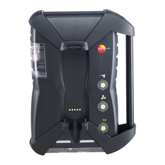
Page 26: Meas. Box
4 Product description 4.2. Meas. box 4.2.1. Overview 1 Condensate trap and condensate container,... -
Page 27: Status Display
4 Product description 2 Locking/unlocking button for Control Unit 3 Measuring gas particle filter 4 Filter fresh air inlet (option: fresh air valve / measurement range extension overall (5x)) 5 Contact bar for connection to Control Unit 6 Guide pins for locking with Control Unit 7 Diluting gas filter 8 Status display 9 Full-view slider for marking/identification... -
Page 28: Connections / Interfaces
Plugged in covering cap: Position ( ) must not be changed! 11 Pressure ports p+ and p- 12 Testo Data bus 4.2.4. Functions / instrument options Some functions are available as optional extras. The functions your meas. box is equipped with (condition as delivered) can be read on the identification plate on the bottom side of the meas. -
Page 29: Menu Guidance Meas. Box
4 Product description Imprint Description Special main gas pump for long-term measurement Measurement range extension (individual dilution with selectable dilution factors) DC-voltage input (11…40V DC) Δp-0 Automatic pressure zeroing for flow measurement Gas preparation, by means of reduced and constant measuring gas dew point temperature for higher measuring accuracy Fresh air valve for overall dilution (x5) to measure high flue gas values. - Page 30 4 Product description Main menu Menu Description Device Dilution Set the dilution factor settings Measurement view Configure the display, set measurement parameters and units for selected application and measurement type Units Set units for display variables Date / time Set date, time, time format: Power Options Set automatic instrument shut-down and switch off display backlight in...
-
Page 31: Modular Flue Gas Probe
4 Product description 4.2.6. Modular flue gas probe 1 Removable filter chamber with window and particle filter 2 Probe handle 3 Connecting cable 4 Connector plug for measuring instrument 5 Probe module lock release 6 Probe module... -
Page 32: First Steps
7h (charging with mains adapter) or approx. 14h (charging via Testo Data bus). In the case of Testo data bus cables >90 m, the rechargeable battery for the control unit can no longer be charged via the Testo data bus cables when the control unit is switched off. -
Page 33: Charging The Rech. Batt. Of The Meas. Box
Charging via meas. box ✓ Control Unit is locked to meas. box or is connected via the Testo Data bus cable. ✓ The meas. box is supplied via the mains unit. During operation with low charge power or in switched off state. -
Page 34: Connecting Probes / Sensors
5 First steps The Control Unit is powered by the mains unit. If the Control Unit is switched off the rech. batt. charging process will start automatically. Switching the Control Unit on has the effect of stopping battery charging and the Control Unit being powered via the mains unit. - Page 35 5 First steps > Occupying the trigger input, with external voltage supply (5...12 V): > Occupying the trigger input, with supply via instrument voltage (12 V): In case of supply via instrument voltage the flue gas analyser can only be started via the trigger input from switched off state when the mains plug is plugged in.
-
Page 36: Connecting System Components
5.2.4.2. Connection using a Data bus cable (accessory part to a bus system) testo data bus cables must not be used during electrical storms. Before connecting to a bus system, all analyzer units must first be equipped with the identical country version and... - Page 37 5 First steps If testo easyEmission software is connected via a control unit to measuring boxes, the number of measuring boxes must not be changed. To add new measuring boxes, end the testo easyEmission software, connect the new measuring box and restart the testo easyEmission software.
- Page 38 5 First steps Bus address The bus address of each component connected to the Testo data bus must be unambiguous. The bus address of the connected component can be changed, if necessary. Bus Address → [Edit]. 2. Setting a new bus address: ], [◄], [►].
-
Page 39: Connection Via Bluetooth (Option)
Electrical termination of the bus system The Data bus system is linear in structure. The Control Unit or the Testo Data bus controller with USB connection represents the beginning of the line. The end is represented by the last components connected in the system (meas. -
Page 40: Switching On
5 First steps Via Bluetooth ® the Control Unit can be connected to a meas. box or a PC/Notebook, as long as both components are equipped with this function, see Bluetooth®, page 56. ® The Bluetooth connection between measurement box ®... -
Page 41: Calling Up A Function
5 First steps The Welcome Screen is displayed (approx. 5s) The Control Unit display screen appears. The Control Unit searches for connected meas. boxes and shows these as independent tabs in the display. Control Unit and meas. box are not connected: If the Control Unit has already been switched on, you must press once again for a short moment to set up a... -
Page 42: Printing / Saving Data
5 First steps 6. Save the entry: [Finished]. Input editor 1. Select the value to be changed (character): [▲], [▼], [◄], [►]. 2. Accept value: [OK]. Options: > Toggle between characters and special characters: ← → → → Select Ι &$/ Ι: [▲], [▼]... -
Page 43: Search For Meas. Boxes
Control Unit (only available via tab) > → Search for boxes → [OK]. Meas. boxes connected via Testo Data bus: are displayed (tabs) Meas. boxes connected via Bluetooth ® • Meas. box found: Meas. box and Control Unit are connected automatically •... -
Page 44: Folders / Locations
5 First steps > press The rinse phase starts. The flue gas analyser switches off. It is normal for the fan of the meas. box to run on for a while. 5.3. Folders / Locations (only available via Meas. Box tab) All readings can be saved under the currently active location. - Page 45 5 First steps Parameter Description Pitot Tube The parameter "Pitot tube factor" influences the Factor measurement of flow speed, volume flow rate and mass flow. The Pitot factor depends on the type of Pitot tube used: Straight Pitot tubes: Factor = 0.67 Prandt’l Pitor tubes (bent): Factor = 1 Humidity The parameter "Humidity"...
-
Page 46: Measurement Records
5 First steps Parameter Description Dewpoint The parameter "Dewpoint" (combustion air dewpoint) influences the calculation of qA (flue gas loss) and flue gas dew point. The factory setting for the dewpoint is 1.5°C. To achieve a higher accuracy, the values can be adjusted to the actual ambient conditions. - Page 47 5 First steps e.g. to be able to transport these for evaluation by PC software, while the meas. box remains at the location. For easy assignment the measurement records are saved under the serial number of the meas. box. The data (folders, locations, readings) contained in these records are displayed like in the meas.
-
Page 48: Instrument Diagnosis
5 First steps 5.5. Instrument diagnosis Important operating values and instrument data are displayed. A gas path check can be carried out. The status of the sensors and any device errors not yet rectified are displayed. Calling up the function: >... -
Page 49: Instrument Information
5 First steps 5.5.4. Instrument information > Device information → [OK]. Information is displayed. The fill level of the condensate trap is only displayed if the condensate trap is plugged onto the analyzer unit. -
Page 50: Using The Product
6 Using the product Using the product 6.1. Performing settings 6.1.1. Assigning the right hand function key Options The right function key can have a function from the menu assigned to it. The menu Options is accessed via the left function key and is available in many different menus. - Page 51 6 Using the product Factor Ratio of diluting gas: Measuring gas no dilution 1 : 1 4 : 1 x 10 9 : 1 x 20 19 : 1 x 40 39 : 1 Auto dilution 4 : 1 If the dilution stage auto-dilution is selected, dilution (5x) is activated automatically when the set switch-off threshold of the...
-
Page 52: Measurement View
6 Using the product Device settings [OK] Dilution [OK] > → → → → 1. Select to dilute all (x5): → [Change]. 2. Select setting: [On] / [Off]. 3. Confirm the entry: [OK]. 6.1.2.2. Measurement view Meas. Box (only available via tab) The parameters / units and the display representation (number of readings displayed per display page) can be set. - Page 53 6 Using the product Display Measurement parameter Effg Efficiency under due consideration of the heat value range Carbon monoxide Carbon monoxide undiluted AmbCO Ambient carbon monoxide Nitrogen monoxide Nitrogen dioxide Nitrogen oxide Sulphur dioxide Hydrogen sulphide Hydrocarbon Hydrogen (this is only an indicator value and is used to compensate the cross-sensitivity) λ...
-
Page 54: Units
6 Using the product Change parameter / unit in a line: 1. Select the line: [▲], [▼] [Change] → 2. Select the parameter: [▲], [▼] [OK] → 3. Select the unit: [▲], [▼] [OK] → 4. Save changes: [OK] Options: >... -
Page 55: Date / Time
6 Using the product 6.1.2.4. Date / time This function is available in both the meas. box and the Control Unit. Changes are accepted for the Control unit and for the meas. box. Date, time mode and time can be set. Calling up the function: >... -
Page 56: Bluetooth
To be able to transfer data to a record printer via infrared or Bluetooth interface, the printer used must be enabled. The following printers can be used with the testo 350: - infrared high-speed printer (order no. 0554 0549) - Bluetooth ®... -
Page 57: Language
Information concerning assignment table, basis of calculation and country version see www.testo.com/download-center If several components with different country versions are connected, the components will automatically change to the country version of the Control Unit when the Control Unit is connected. -
Page 58: Password Protection
6 Using the product [OK] 2. Confirm confirmation request: → The system is restarted. If the control unit is connected via Bluetooth to the measuring box, when the measuring box is restarted, the control unit should be used to search again for the measuring box (see Search for meas. -
Page 59: Data Bus
2 max 2 max Besides the already pre-configured fuels, up to 5 more fuels can be configured in a customized way (e.g. with the testo easyEmission software). Fuel parameter, see www.testo.com/download-center (registration required). In order to maintain the measuring accuracy of the instrument one must choose or configure the correct fuel. -
Page 60: Sensor Settings
Recommended test gas concentrations and compositions can be found in the Testo Test Gas Manual (order no. 0980 2313 version D) or in the Download Centre. Calling up the function:... -
Page 61: Sensor Protection
6 Using the product exist, the sensor can also be switched off manually. CxHy-Sensor starts the flue gas analyser with a zeroing phase (30s). For proper functioning the sensor is heated up to approx. 500°C, duration: approx. 10min. This means that the sensor needs to be zeroed again 10min after the device has been switched on, in order to prevent drifting (into the "minus"... - Page 62 (calibrated) and, if required, adjusted. The calibration/adjustment can be carried out by the user or by a qualified service centre approved by Testo. To ensure that specific accuracies are retained, Testo recommends testing every six months and recalibration when required.
- Page 63 6 Using the product > → Sensor settings → [OK] → Calibration /Adjust → [OK]. Possibly: [Enter] [Next] > Enter the password: → Enter password → → [OK]. Gas zeroing (30s). Perform calibration / adjustment of CO-, SO -, NO -, NO-, O S-, CxHy-sensors: WARNING...
-
Page 64: Ppmh Counter
6 Using the product WARNING Dangerous gases Danger of poisoning! > Observe safety regulations / accident prevention regulations when handling test gas. > Use test gases in well ventilated rooms only. Application of test gas via service adapter (0554 1205) is recommended, or apply test gas directly to the probe tip to avoid possible absorptions in the gas path. -
Page 65: Calibration Data
6 Using the product Reset hour meter (NO sensor only) [Reset]. [OK] 2. Confirm confirmation request: → 6.1.4.6. Calibration data Use this function to display the current calibration data (comparison of nominal value and actual value without sensor adjustment). Calling up the function: >... -
Page 66: Programs
6 Using the product Switching negative values on/off [Change] 2. Select setting: [▲], [▼] [OK] 3. Confirm the entry: 6.1.5. Programs Five flue gas measuring programs can be set, saved and executed. Trigger function (trigger signal as start/stop criterion) is only available for devices with the trigger input option. - Page 67 6 Using the product Parameter Function Reading per Mean value Yes: mean value the measurement system saves one reading per second (measurement rate cannot be changed). At the end of the gas phase, a mean value is calculated from the individual values saved thus far and stored.
- Page 68 6 Using the product Parameter Function Stop Determining the stop criterion • The measuring program is stopped at any time (the function key automatically changes to the start function) • Time The recoding of readings stops at a desired time. •...
-
Page 69: Measuring
The testo 350 can be operated as follows: • lying down • hanging horizontally down by its handle • plugged vertically to the wall bracket by the handle To prevent measuring errors the position of the testo 350 must not be changed during a measurement. - Page 70 6 Using the product Under ambient temperatures of <10°C the CO -(IR) sensor requires a shorter heat-up time to reach full measuring accuracy. At -5°C this typically is 15min. Before switching on > Check whether: • All system components are properly connected. •...
-
Page 71: Using The Flue Gas Probe
6 Using the product Zeroing takes place automatically when the CxHy sensor is activated. To ensure that accurate CxHy readings are obtained, you should then wait about 10min (with the instrument switched on) before starting another zeroing process manually. To prevent the CxHy sensor from drifting during lengthy measurement operations, zeroing should be carried out from time to time. - Page 72 For this measurement type, both analyzer units must have a fresh air valve. If one of the two meas. boxes is equipped with a measurement range extension (individual dilution), the test 350 will automatically recommend this meas. box to be used for Before cat.
-
Page 73: Flue Gas, Flue Gas + M/S, Flue Gas + Δp, Program For All Meas. Boxes, Flue
6 Using the product → [OK]. 3. Selecting fuel: 6.2.3.1. Flue Gas, Flue Gas + m/s, Flue Gas + Δp, Program for all meas. boxes, Flue Gas before + after catalyst The flue gas menus (Measurement Type) are the central measuring menus, which –... - Page 74 6 Using the product Calling up the function: ✓ Application selected. > Choose the measurement type: → [OK]. Options > [Options] → Save: The readings are saved in a record. > [Options] → Print: The readings from a record are printed. >...
-
Page 75: Draught-Measurement
Do not measure for longer than 5 min, as the drift of the pressure sensor could have the effect that the readings are outside the tolerance limits. The automatic pressure zeroing (retrofit by Testo Service) automatically zeroes the pressure sensor at regular intervals (60s), to prevent the typical drift of the pressure sensor. -
Page 76: Smoke Number/Hct
6 Using the product Options: [Options] → Save: The readings are saved in a record. > [Options] → Print: The readings from a record are printed. > [Options] Show Graphic: The readings are displayed in > → form of a line graph. [Options] Configure Graphic: The measurement... -
Page 77: Oil Flow Rate
6 Using the product [Options] Enter Gas Flow: Set the gas flow value. > → [Options] Change unit: The unit for the gas flow can be > → changed (m3 > l l > m3). 6.2.3.5. Oil flow rate The function is only available if the chosen fuel is an oil. Calling up the function: >... - Page 78 6 Using the product The analog output unit 0554 3149 (accessory) is suitable for the output of up to 6 measuring channels in the form of analog signals (4 to 20mA). The analog output unit is connected to the instrument via data bus, and the configuration can be carried out via the control unit.
- Page 79 6 Using the product Connections The channels are electrically isolated towards the Testo databus. However, the individual channels are not electrically isolated among each other. When connecting you must make sure that there are no undesired ground loops! In both channels the positive output is connected to the ground connection of the recorder.
-
Page 80: Maintaining The Product
Maintaining the product 7.1. Changing the rechargeable battery Control Unit The rech. batt. pack can only be changed by the Testo service. Meas. box ✓ The meas. box must not be connected to a mains socket. ✓ The meas. box must be switched off. -
Page 81: Changing / Retrofitting Sensors
CO H -compensated sensors within the scope of the first German Federal Immission Control Ordinance (BImSchV) must only be changed / retrofitted by a Testo service centre. When retrofitting a sensor, the associated measurement parameter and unit must be enabled, see Section 6.1.4 Sensor settings. - Page 82 7 Maintaining the product 4. Take the sensor out of the bracket. 5. Pull the hose connections off the connecting nipples of the defective sensor / the bridge. 6. Remove the defective sensor /bridge from the slot. > NO- / NO sensors: Remove the auxiliary circuit board.
- Page 83 7 Maintaining the product Slot Sensors S, CO, CO , NO, NO , SO S, CO, COl , NO, NO , SO -(IR), NO S, CO, CO , NO, , SO CO, CO , NO, NO , SO , CxHy CO, CO , NO, NO , SO...
-
Page 84: Replacing The Filter For No Sensors
7 Maintaining the product 11. Switching on the analyzer box. After replacing an O sensor, allow a 15-minute acclimatization time before using the instrument (establishing the supply voltage and initial stability time for new sensors). 7.4. Replacing the filter for NO sensors ✓... -
Page 85: Cleaning The Modular Flue Gas Probe
7 Maintaining the product 7.6. Cleaning the modular flue gas probe ✓ Disconnect the flue gas probe from the measuring instrument prior to cleaning. 1. Release the probe catch by pressing the key on the probe handle and remove the probe module. 2. -
Page 86: Condensate Trap / Condensate Container
7 Maintaining the product 4. Fit a new probe module on the handle and engage in place. 7.9. Condensate trap / condensate container With the gas preparation option fitted, the condensate is separated from the measuring gas and is led into a condensate container that is isolated from the gas path. -
Page 87: Checking / Replacing The Dirt Filter
7 Maintaining the product 2. Unlock the condensate trap / condensate container and pull it vertically off the meas. box. 3. Open the drain plug (1) and let the condensate run out into a sink. 4. Wipe off any drops still on the condensate outlet with a cloth and close the condensate outlet. -
Page 88: Cleaning / Replacing The Pump
7 Maintaining the product 1. Open the filter chamber: Turn the filter cover anti-clockwise and take it off. 2. Remove the dirt filter and replace it with a new one 0554 3381). 3. Attach the filter cover and lock by turning it clockwise. The rib on the filter cover must be parallel to the handle. -
Page 89: Cleaning The Main Gas Pump
7 Maintaining the product 3. Open the cover of the service compartment (locking clip) on the back of the meas. box. 1 Condensate pump 2 Main gas pump 3 Rinsing / feed pump for diluting gas 7.11.1. Cleaning the main gas pump 1. -
Page 90: Changing The Main Gas Pump
7 Maintaining the product > If necessary, blow the inlet and outlet sockets out with compressed air. 8. Reattach the pump diaphragms with the circlips. 9. Place the pump head on the main gas pump and fasten with the screws (Torx spanner T 9). 10. -
Page 91: Replacing The Motor Of The Condensate Pump
7 Maintaining the product 2. Unlock the two lateral clip locks of the condensate pump and pull off the pump head. 3. Pull the inlet and outlet hoses off the sockets on the meas. box. 4. Plug the inlet hose (length 25mm) and outlet hose (length 31mm) of the new pump onto the connecting sockets of the meas. - Page 92 7 Maintaining the product 2. Unlock the two lateral clip locks of the condensate pump and pull off the pump head. 3. Pull the inlet and outlet hoses off the sockets on the meas. box. 4. Loosen the motor on the condensate pump (short anti- clockwise turn).
-
Page 93: Replacing The Filtration Non-Woven In The Gas Cooler
7 Maintaining the product 8. Place the motor of the condensate pump into the bracket. 9. Fasten the motor on the condensate pump (short clockwise turn). 10. Plug the inlet hose (length 25mm) and outlet hose (length 31mm) of the pump onto the connecting sockets of the meas. box. -
Page 94: Recommended Maintenance Cycles
7 Maintaining the product 4. Replace the exhausted filter with a new filtration non-woven. 5. Close the cover. 6. Plug on the hose. 7. Plug the condensate container on the measuring box. 7.13. Recommended maintenance cycles Component Service life Remedy Main gas pump 2500h Renew the pump... -
Page 95: Tips And Assistance
Dilution Gas flow rate in dilution path too high / too low > Please contact your local dealer or the Testo Customer Service. sensor exhausted > Replace the O sensor ... Signal too high Signal of indicated sensor is too high. -
Page 96: Accessories And Spare Parts
Bluetooth via Bluetooth connection directly via the measuring box. If we could not answer your question, please contact your dealer or Testo Customer Service. Contact data see back of this document or website www.testo.com/service-contact. 8.2. Accessories and spare parts Printer Description Article no. - Page 97 8 Tips and assistance Description Article no. Spare thermal paper for printer, permanent ink 0554 0568 Filter Description Article no. Particle filter for probe handle 0554 3385 20 pcs. dirt filters for measuring box 0554 3381 Replacement sintered filter for probe 0554 3372 Spare filter for NO-sensor 0554 4150...
- Page 98 0393 0104 NO, filter not replaceable 0393 0150 0393 0200 0393 0250 0393 0251 2low 0393 0152 -H2-comp. 0393 0102 -(IR) Testo-Sevice 0393 0350 CxHy 0393 0300 Retrofits CO, H2-comp. sensor 0554 2104 NO sensor 0554 2150 sensor 0554 2200...
- Page 99 8 Tips and assistance sensor 0554 2152 -H2-comp. sensor 0554 2102 -(IR) sensor Testo-Sevice S sensor 0554 2350 CxHy-sensor 0554 2300 Bluetooth ® module for Control Unit and meas. box Testo-Sevice Gas cooler / gas preparation Testo-Sevice Fresh air valve...
-
Page 100: Updating The Instrument Software
If the battery is not fully charged, this will affect the firmware update. The flue gas analyser must then be sent in to Testo Service. Once the instrument software has been updated, the descriptions in the operating instructions will no longer match the instrument functions. - Page 101 The status display flashes alternately green and red. This process may take a few minutes. 8. Remove the connecting cable from the meas. box 350. After updating of the instrument software (Firmware) has been completed the meas. box will automatically reboot and is ready...
-
Page 102: Appendix
9 Appendix Appendix Recommendation for emission measurements over an extended period of time The following table shows recommendations for rinse times for measurements with high concentrations and recommendations for calibration cycles for emission measurements over an extended period (via a measuring program): >... - Page 103 O shut-down...) -(IR) no rinse cycles required If the testo 350 is not used for measurements over an extended period, but rather, for example, for random measurements during start-up, servicing and adjustment of industrial combustion systems, process systems, power...
- Page 104 9 Appendix annual check of the testo 350 by Testo Service is recommended. Cross-sensitivities This table is valid for new sensors with possibly unused filters, and for cross-gas concentrations in the ppm-range (down to less than 1000ppm). The value "0" means: <1% cross-sensitivity.
- Page 105 9 Appendix Target gas Cross-gas CO(H CO(H 100% <3% -80% <3% -80% 2 low CxHy 130% no data no data no data <10% after H -compensation Is compensated with indication H from the CO(H ) sensor...
- Page 106 0970 3511 en 05_GB...
Need help?
Do you have a question about the 350 and is the answer not in the manual?
Questions and answers