
Related Manuals for TESTO 300 Pro Smoke Edition


Summary of Contents for TESTO 300 Pro Smoke Edition
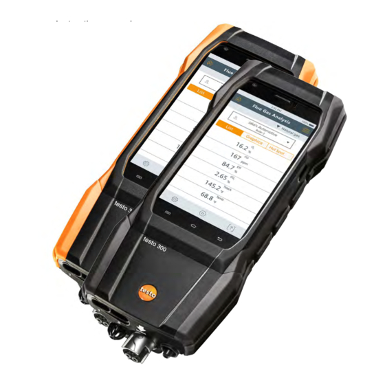
- Page 1 300 Smoke Edition / testo 300 Pro - Combustion Analyzer Instruction manual GlobalTestSupply www. .com Find Quality Products Online at: sales@GlobalTestSupply.com...
-
Page 2: Table Of Contents
Contents Contents 1 About this document ................... 7 1.1 Symbols ....................7 1.2 Warning notices ..................7 2 Safety and disposal ..................8 3 Product-specific safety instructions ............8 4 Authorizations and certification ..............8 5 Specifications ....................9 6 Product description ................... 10 6.1 Front view ..................... - Page 3 8.2.9 Server Information..............37 E-mail ..................37 8.2.10 My Apps ................39 8.2.11 8.2.12 Help ..................40 Please register your testo 300 ......40 8.2.12.1 Tutorial ..............40 8.2.12.2 8.2.12.3 Setup Wizard ............40 8.2.12.4 Update via USB ............ 41 9 Performing the measurement ..............
- Page 4 Contents Smoke Number ..............50 9.6.5 Differential pressure ............... 51 9.6.6 9.6.7 Differential temperature ............51 9.6.8 air (EU regulation) ............52 Clock Meter ................52 9.6.9 9.6.10 Oil flow calculation ..............53 9.6.11 CO Ambient ................53 Pipe Commissioning (EU regulation) ........54 9.6.12 Pressure Drop test (EU regulation) ........
-
Page 5: About This Document
1 About this document 1 About this document • The instruction manual is an integral part on the instrument. • Keep this documentation to hand so that you can refer to it when necessary. • Please read this instruction manual carefully and familiarize yourself with the product before use. -
Page 6: Safety And Disposal
2 Safety and disposal 2 Safety and disposal Take the testo information document into account (accompanies the product). 3 Product-specific safety instructions CAUTION The condensate may be acidic. Risk of burns to the hands! - Wear acid-resistant safety gloves, glasses and overalls to empty the condensate. -
Page 7: Specifications
5 Specifications 5 Specifications The testo 300 is a measuring instrument for flue gas analysis on applications, such as • residential, commercial and industrial applications (oil, gas, wood, coal) • low-temperature and condensing boilers • boilers, furnaces and gas heaters. -
Page 8: Product Description
6 Product description 6 Product description Front view 1 USB interface/ 4 User interface power connection 2 Gas outlet 5 Condensate trap 3 On/Off button 6 Connections GlobalTestSupply www. .com Find Quality Products Online at: sales@GlobalTestSupply.com... -
Page 9: Rear View
6 Product description Rear view 1 Attachment point for carrying 2 Magnets strap Connections 1 Probe connections for additional 3 Flue gas socket probes 2 Integrated ambient air probe 4 Differential pressure measurement connection There must be no more than one extension lead (0554 1202) connected between flue gas socket and flue gas probe. -
Page 10: Compact Flue Gas Probe
6 Product description Compact flue gas probe 1 Removable filter chamber with 3 Connector plug for measuring window and particle filter instrument 2 Probe handle 4 Connection cable Modular flue gas probe Removable filter chamber with Connector plug for measuring window and particle filter instrument 2 Lock release... -
Page 11: First Steps
7 First steps 7 First steps Commissioning Take the information in the testo information document (included with the product) into account for this. Power supply / Battery The measuring instrument is supplied with a rechargeable battery. Fully charge the battery before use. -
Page 12: Power Supply (Ac) Operation
For longer measurements involving AC operation, Testo recommends using a combustion air temperature probe with connection cable. Self- heating of the instrument during AC operation may influence the combustion air temperature measurement using a mini ambient air probe. -
Page 13: Keypad
7 First steps Description Zooming To make a section of the display larger or smaller, touch the display with two fingers and move them apart or together. Dragging You can move an element by touching it, holding it and dragging it to the required position. -
Page 14: Switch Instrument On And Off
7 First steps Switch instrument on and off Current Action Function status Instrument Press the button for Instrument is turned on. a long time (> 3 s) When the measuring instrument is started for the first time, the setup wizard guides you through the following setting parameters step by step: Country version (basis of calculations) Language... -
Page 15: Connect Probes
7 First steps Connect probes Flue gas probes Instrument is turned on. Insert the connector plug into the flue gas socket and lock it in place by turning it slightly clockwise (bayonet lock). There must be no more than one extension line (0554 1201) between measuring instrument and flue gas probe. -
Page 16: Using The Product
8 Using the product 8 Using the product User interface Measurement types Status bar Main menu Fuels Open selection list Select Customer/Measuring site Select reading display type: • List • Graphics • Hot Spot Edit measurement data Start measurement Pause measurement Stop measurement Options GlobalTestSupply... -
Page 17: Main Measurement Display - List
8 Using the product Further symbols on the user interface (without numbering) Refresh measurement One level back One level back One level back Cancel process Print values Save report Save and send report 8.1.1 Main measurement display - List The measurement units and the number and order of the measurement parameters displayed in the Main measurement display –... -
Page 18: Main Measurement Display - Graphics
8 Using the product 8.1.2 Main measurement display - Graphics In the Main measurement display - Graphics, the reading progression can be displayed as a line diagram. A maximum of 4 measurement parameters can be set at any one time. Only those measurement parameters can be displayed that are available in the Main measurement display - Graphics. -
Page 19: Main Measurement Display - Hot Spot
8 Using the product Main measurement display - Hot Spot 8.1.3 Search for hot spot: Measurement view is enabled. Call up function: Hot Spot Start search: Perform zeroing. The measurement starts automatically after zeroing. Align the flue gas probe in the flue so that the probe tip is in the hot spot (area of the highest flue gas temperature... -
Page 20: Overview Of Main Menu ( )
8 Using the product Overview of main menu ( Main menu Description Customer / Measuring site Create, edit and delete customer and system information. Tests Call up, delete and send measurements that have been performed (various formats possible). Saved reports Call up and delete measurement report. -
Page 21: Customer / Measuring Site (Point)
Help Aids Device Registration Tutorial Setup Wizard Help Online Testo Website Update via USB 8.2.1 Customer / Measuring site (point) Create, edit and copy Customer / Measuring site information. Customer / Measuring site can be deleted. Customer / Measuring site Call up function: ... - Page 22 8 Using the product The following functions are available: View/edit existing data about 1 Search Customer / Measuring site Create new Customer / Measuring site Search Search operating field. Text cursor flashes. Enter search test using the text editor. Via the search text, only the Customer / Measuring site is displayed that contains characteristics of the search text.
- Page 23 8 Using the product Confirm each input with Customer/Company Name input field is a required field and must be filled in. Save. Customer is created. To be able to select a customer, at least one measuring site must be created and selected! Create new measuring site A customer is created.
-
Page 24: Tests
8 Using the product Edit measuring site Customer input screen is open. Measuring site button. Select Measuring site. Edit data. Save. 8.2.2 Tests Tests Call up function: Tests menu is displayed. Select customer. Open measuring site. Measurements for the selected customer / measuring site can be viewed and deleted... -
Page 25: Saved Reports
8 Using the product Category Description Format and print Select output format(s): (comma separated text file, e.g. for Microsoft ® Excel) ZIV 2.00 (XML file, complying with the regulations of the Guild of Master Chimney Sweeps in Germany). Customer data Enter / add contact details. - Page 26 8 Using the product Delete report(s) Touch required report for >2 sec. Report is marked. If necessary, mark more reports by tapping. Delete report(s): tap Send report(s) Touch report for >2 sec. Report is marked. If necessary, mark more reports by tapping symbol.
-
Page 27: Gas Path Check
8 Using the product 8.2.4 Gas path check Regular tightness testing of measurement systems (measuring instrument + flue gas probe) is recommended. Call up function: Gas path check Gas path check starts automatically. Place the black sealing cap on the tip of the flue gas probe. ... - Page 28 8 Using the product Set country version Country version (basis of calculations) selection field. The available country versions are displayed. Select country version. The query Change country version? is displayed. Tap Next. Configuration of the country version can be ended by Device Settings.
-
Page 29: Wi-Fi
8 Using the product Wi-Fi 8.2.5.2 A radio link, such as a Wi-Fi, is not needed for performing measurements. Set up a connection to a Wi-Fi router or a Wi-Fi hotspot. The connection allows sending of measurement reports by e-mail. Device Settings Call up function: Wi-Fi. -
Page 30: Date/Time
8 Using the product Date/Time 8.2.5.3 You can set the date, time and time zone in the Date/Time menu. You can choose between the 24 hr or AM/PM formats for the time. If the Wi-Fi has already been enabled, the Date/Time provided by the network is automatically set. - Page 31 8 Using the product Set Date/Time manually Tap Date/Time. Autom. Date/Time. Select Off. Autom. Date/Time is disabled. The pop-up window closes automatically. Date. Select date via the calendar and confirm with OK. GlobalTestSupply www. .com Find Quality Products Online at: sales@GlobalTestSupply.com...
-
Page 32: My Company Address
8 Using the product Time. Tap hour and set. Tap minute, set and confirm with OK. Device Settings Back to the menu: tap Set time zone manually Time Zone. Autom. Time Zone and disable ( ). Select time zone. Select desired time zone. Back to the Device Settings menu: tap... -
Page 33: Bluetooth
8 Using the product Bluetooth 8.2.5.5 Enable Bluetooth to print out or transmit measurement data. Call up function: Device Settings Bluetooth ® Enable/disable Bluetooth by tapping the selection field. Back to the Device Settings menu: Tap Hotspot 8.2.5.6 Enable a hotspot to be able to transmit readings to software / industry software. The interface must also be available in the software / industry software. -
Page 34: Co/No Sensor Protect
8 Using the product 8.2.5.8 CO/NO sensor protect Limit values can be set to protect the CO/NO sensors against overload. Sensor protect is enabled if these are exceeded: • Fresh air dilution if exceeded (only for instruments with the "Dilution" option) •... -
Page 35: Sensor Diagnosis
8 Using the product Keypad appears. Enter the value via the keypad. Confirm each input with ✓. Tap [OK]. 8.2.6 Sensor Diagnosis Overview of the sensors fitted and their condition. Call up function: Sensor Diagnosis 8.2.7 Error List Call up error reports. Call up function: Error List 8.2.8 Device Information... - Page 36 • Open e-mail client, e.g. gmail, on a PC and check e-mail reception. The provider may have sent a security e-mail which has to be confirmed before the e-mail account on the testo 300 is accepted. • Enable IMAP account To do this, call up your e-mail account on the PC.
-
Page 37: My Apps
8 Using the product Call up e-mail account Call up function: E-Mail Inbox menu is opened. Create e-mail: tap Compose menu and the keypad is opened. Enter the e-mail address via the keypad. Fill in subject and create text. If required, additional files can be attached to the e-mail using the paper clip symbol. -
Page 38: Help
Please register your testo 300 Call up function: Testo would like to offer you the best possible customer service. Register your instrument so that, when you call, our employees in Customer Service have all the information they need available at all times, so that they can quickly provide you with further assistance. -
Page 39: Update Via Usb
8 Using the product Update via USB 8.2.12.4 Call up function: Help Update via USB Confirm info with OK. Firmware update is started. Insert the connecting cable (0449 0134) into the USB port on the measuring instrument, then connect it to the PC. ... -
Page 40: Performing The Measurement
Gas zeroing The gas sensors are automatically zeroed after the instrument is turned on. testo 300 without option of probe zeroing in the flue gas: The flue gas probe must be in fresh air during the zeroing phase (30 sec)! -
Page 41: Carry Out Gas Path Check
9 Performing the measurement Carry out gas path check Regularly check the measurement system (measuring instrument + flue gas probe) for leaks. Too high an O2 value may be an indicator of a leaking measurement system. > Gas path check. Use of flue gas probe Check thermocouple before use >... -
Page 42: Overview Of Measurement Types
9 Performing the measurement Align the flue gas probe in the flue gas duct so that the probe tip is in the hot spot (area of the highest flue gas temperature Max Tstack). Grey value/grey pointer: Display of current flue gas temperature Orange value/orange pointer: Display of maximum flue gas temperature ... -
Page 43: Overview Of Options
9 Performing the measurement Measurement types Differential temperature Clock Meter Oil flow calculation CO Ambient Pipe Commissioning Pressure Drop test Pretest Overview of options ( Options Description Config. Measurem. display Add, delete ( ), measurement parameters, display sequences ( ) and edit units (click on Unit). -
Page 44: Configure Measurement Display
9 Performing the measurement 9.6.1 Configure measurement display Call up function: Options Config. measurem. Display Edit Display menu is opened. Measurement parameter - Add: tap to open selection list of measurement parameters. - Delete: tap on - Edit unit: tap on the measurement parameter you want to edit. Tap on the required measurement unit in the selection list that has been opened. - Page 45 9 Performing the measurement Display Measurement parameter Carbon dioxide Eff net Efficiency without consideration of the heat value range Efficiency with consideration of the calorific value range Carbon monoxide Draft Flue draft CO AF Undiluted carbon monoxide Corrected CO for environmental regulation ExAir Excess Air CO amb...
-
Page 46: Flue Gas Analysis
9 Performing the measurement 9.6.2 Flue Gas Analysis To maintain the measuring accuracy of the instrument, the correct fuel must be selected or configured. (Fuels) > Select fuel. To achieve usable measurement results, the test time of a flue gas measurement should be at least 3 minutes and the measuring instrument should display stable readings. -
Page 47: Draft-Measurement
9 Performing the measurement For the draft measurement, the minus connection for differential pressure measurement must be free (ambient pressure, not closed). Tap on the draft reading display next to it. End measurement: tap 9.6.3 Draft-Measurement A flue gas probe must be connected. ... -
Page 48: Co Air Free
9 Performing the measurement 9.6.4 CO Air free A multi-hole probe (0554 5762) must be connected. Call up function: CO Air free Start measurement: tap Reading is displayed. End measurement: tap 9.6.5 Smoke Number Smoke Number Oil depos. parameters are only available for oil fuels. -
Page 49: Differential Pressure
9 Performing the measurement 9.6.6 Differential pressure WARNING Dangerous mixture of gases! Danger of explosion! - Make sure there are no leaks between the sampling point and the measuring instrument. - Do not smoke or use naked flames during the measurement. The gas pressure kit (0554 1203) must be connected. -
Page 50: O 2 Air (Eu Regulation)
9 Performing the measurement 9.6.8 O air (EU regulation) An O dual wall clearance probe (0632 1260) must be connected. Call up function: Start measurement: tap Reading is displayed. End measurement: tap 9.6.9 Clock Meter The function is only available if the chosen fuel is a gas. The gas burner capacity is calculated by means of the gas amount consumed. -
Page 51: Oil Flow Calculation
9 Performing the measurement 9.6.10 Oil flow calculation The function is only available if the chosen fuel is an oil. This function is used to calculate the capacity of the burner from the set oil pressure and the oil flow rate of the oil nozzle. Call up function: Oil flow calculation Set oil flow rate of the oil nozzle and oil pressure. -
Page 52: Pipe Commissioning (Eu Regulation)
9 Performing the measurement 9.6.12 Pipe Commissioning (EU regulation) The pipe commissioning (using air or inert gas such as CO or N ) is a tightness test for pipes, including fittings, but without gas appliances and the relevant regulating and safety devices. The pipe commissioning is performed after a load test has been successfully completed on newly laid gas pipes, or after renovation of existing gas pipes, and is used for the acceptance of these pipes. -
Page 53: Pressure Drop Test (Eu Regulation)
9 Performing the measurement Stabilization time is finished. End stabilization time early: tap Measuring time starts. The readings are automatically saved and displayed after the measurement has been completed. The measuring value result can be assessed. Conclude measurement: tap Next. If applicable, repeat measurement: tap 9.6.13 Pressure Drop test (EU regulation) This measurement is performed to test the serviceability of an existing gas pipe... - Page 54 9 Performing the measurement Set parameters or enter values. All values that can be modified have a dotted underlining. Three circle diameters and three pipe lengths can be entered, which are then used to calculate three partial volumes. The pipe volume is calculated by adding these three partial volumes.
-
Page 55: Pretest (Eu Regulation)
9 Performing the measurement 9.6.14 Pretest (EU regulation) > Insert the connector plug of the hose connection kit (0554 1203) into the flue gas socket and lock it in place by turning it slightly clockwise (bayonet fitting). Performing the measurement The pressure socket of the instrument must be free (depressurized, not ... -
Page 56: Overview Of Tests
Saved reports can be retrieved in the main menu. 9.7.1 Print values The current readings are printed via a Bluetooth ® printer (accessories: Testo printer 0554 0621). Carry out print text settings Print text settings can be performed and the reading printout can be supplemented with individual creator information (header: company address;... -
Page 57: Save
9 Performing the measurement Print current readings The printer is turned on and within wireless range. Tests menu is opened. Print values. The test is created and sent to the printer. The test is printed. 9.7.2 Save The measurement data from the last measurement performed of each measurement type are saved on the measuring instrument. - Page 58 9 Performing the measurement Finish test. Options for Tests are opened. Enter/select log data: Category Description Format and print Select output format(s): (comma separated text file, e.g. for Microsoft ® Excel), (XML file, complying with the regulations of the ‘Federal Association of Chimney Sweeps in Germany’).
- Page 59 9 Performing the measurement Print values: tap To save readings: tap Save and send report: tap GlobalTestSupply www. .com Find Quality Products Online at: sales@GlobalTestSupply.com...
-
Page 60: Maintenance
10 Maintenance 10 Maintenance 10.1 Service Testo recommends an annual check of the testo 300 which can be performed by a service center authorized by Testo. Please contact Fr d 10.2 Calibration The measuring instrument is supplied with a calibration protocol as standard. -
Page 61: Clean The Measuring Instrument
10 Maintenance 10.4 Clean the measuring instrument > If the housing of the measuring instrument is dirty, clean it with a damp cloth. Use distilled water, or alternatively mild solvents, such as isopropanol, to clean the flue gas analyzer. CAUTION Improper use of isopropanol! Irritation of the eyes and sensitive mucous membranes! Fumes have a slight narcotic effect! - Page 62 10 Maintenance CAUTION Weak mix of acids in the condensate! Minor injuries! - Avoid skin contact. - Make sure that the condensate does not run over the housing. CAUTION Condensate entering the gas path! Damage to sensors and flue gas pump! - Do not empty condensate trap while the flue gas pump is in operation.
-
Page 63: Open The Measuring Instrument
10 Maintenance 10.6 Open the measuring instrument Only open the measuring instrument when this is required for maintenance purposes (replacing gas sensors). The measuring instrument must not be connected to a mains socket via the mains unit. The measuring instrument must be turned off. When opening/assembling the instrument, take care not to lose any screws that have been removed. -
Page 64: Replace Sensors
10 Maintenance Place the instrument on its front again. Remove the remaining four screws on the back of the instrument. Lift off the back of the instrument. Assembly Perform in reverse order to assemble. Please note: - Lay hoses and lines in the guides intended for this purpose. - Make sure that hoses and lines do not get jammed. -
Page 65: Replace O2 Sensor
10 Maintenance 10.7.1 Replace O2 sensor Measuring instrument is open, see Section Open measuring instrument. Unlock retaining bracket and open out. Remove faulty sensor from the slot. Insert new sensor in the slot. Make sure that the socket on the sensor circuit board is correctly connected to the contact plug. -
Page 66: Change Co, Co H2 And No Sensor
10 Maintenance 10.7.2 Change CO, CO H2 and NO sensor Measuring instrument is open, see Section Open measuring instrument. Remove faulty sensor and hose connections from the slot. Remove hose connections from the faulty sensor/bridge. For NO sensor: Remove auxiliary circuit board. Do not remove the auxiliary circuit board of the NO sensor until immediately before installation. -
Page 67: Clean Modular Flue Gas Probe
10 Maintenance 10.8 Clean modular flue gas probe Disconnect flue gas probe from the measuring instrument. Release probe catch by pressing the key on the probe handle and remove probe module. Blow compressed air through flue gas ducts of the probe module and probe handle (see illustration). - Page 68 10 Maintenance Replace particle filter The filter chamber may contain condensate. This is not a malfunction and will not cause incorrect readings. Open filter chamber: turn slightly counter-clockwise. Remove filter chamber. Remove filter plate and replace it with a new one (0554 3385). Attach the filter chamber and lock it: turn slightly clockwise.
-
Page 69: Replace Thermocouple
10 Maintenance 10.11 Replace thermocouple Release probe catch by pressing the key on the probe handle and remove probe module. Remove thermocouple plug-in head from the socket using a screwdriver and pull thermocouple out of the probe shaft. Insert new thermocouple into the probe shaft until the plug-in head clicks into place. -
Page 70: Technical Data
11 Technical data 11 Technical data Feature Value Temperature measuring instrument -40 to +2192°F Draft measurement -4.01 to +16.06 inH2O Pressure measurement -40.15 to 80.29 inH2O measurement 0 to 21 vol.% CO measurement 0 to 4000 ppm Option: CO measurement 0 to 8000 ppm -compensated) Option: CO measurement with activated... -
Page 71: Contact And Support
11 Technical data Feature Value Power supply Energy storage unit, USB mains unit Energy storage unit service life 10 hrs Lifetime energy storage > 1000 charging cycles Protection class IP 40 Memory 1 million measuring values 5.0" touch display, Display HD 1280x720 pixels Weight Approx.
Need help?
Do you have a question about the 300 Pro Smoke Edition and is the answer not in the manual?
Questions and answers