TESTO 350 Instruction Manual
Flue gas analyzer
Hide thumbs
Also See for 350:
- Instruction manual (108 pages) ,
- Short manual (28 pages) ,
- Instruction manual (106 pages)

Related Manuals for TESTO 350


Summary of Contents for TESTO 350
- Page 1 350 · Flue gas analyzer Instruction manual 800.561.8187 information@itm.co www. .com...
-
Page 2: Table Of Contents
1 Contents Contents Contents ....................3 Safety and the environment ..............6 2.1. About this document ................ 6 2.2. Ensure safety ................... 7 2.3. Protecting the environment .............. 9 Specifications ..................10 3.1. Use ....................10 3.2. Technical data ................11 3.2.1. - Page 3 1 Contents 5.2.4. Connecting system components ..............34 5.2.4.1. Connection using contact strip ............34 5.2.4.2. Connection using a Data bus cable (accessory part to a bus system) ............ 35 ® 5.2.4.3. Connection via Bluetooth (option) ..........38 5.2.5. Switching on ....................39 5.2.6.
- Page 4 1 Contents 6.2. Measuring ..................68 6.2.1. Preparing for measurement ................68 6.2.2. Using the flue gas probe ................70 6.2.3. Applications ....................70 6.2.3.1. Flue Gas, Flue Gas + m/s, Flue Gas + Δp, Program for all meas. boxes, Flue Gas before + after catalyst ........... 72 6.2.3.2.
-
Page 5: Safety And The Environment
2 Safety and the environment Safety and the environment 2.1. About this document This document describes the product testo 350 with the device setting Country version | Germany. > Please read this documentation through carefully and familiarize yourself with the product before putting it to use. Pay particular attention to the safety instructions and warning advice in order to prevent injuries and damage to the products. -
Page 6: Ensure Safety
Use only original spare parts from Testo. > Any further or additional work must only be carried out by authorised personnel. Testo will otherwise refuse to accept responsibility for the proper functioning of the measuring instrument after repair and for the validity of certifications. - Page 7 2 Safety and the environment > Temperatures given on probes/sensors relate only to the measuring range of the sensors. Do not expose handles and feed lines to any temperatures in excess of 70 °C unless they are expressly permitted for higher temperatures. >...
-
Page 8: Protecting The Environment
> At the end of its useful life, send the product to the separate collection for electric and electronic devices (observe local regulations) or return the product to Testo for disposal. 800.561.8187 information@itm.co www. -
Page 9: Specifications
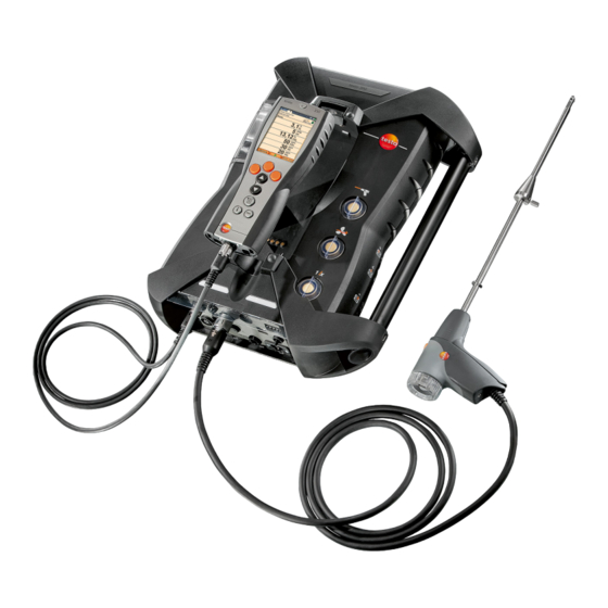
3 Specifications Specifications 3.1. The testo 350 is a portable flue gas analyser for professional flue gas analysis. The instrument consists of the Control Unit (control unit for displaying readings and controlling the meas. box) and the meas. box (measuring instrument). Plug-type contacts, databus ®... -
Page 10: Technical Data
3 Specifications testo 350 must not be used: • for continuous measurements • as a safety (alarm) device • to measure combustion gases (before the actual combustion process) ® testo 350 with Bluetooth option: The use of the wireless module is subject to the... - Page 11 The FCC demands that the user is to be informed that with any changes and modifications to the device, which have not been explicitly approved by testo AG, the right of the user to use this device will become null and void.
-
Page 12: Declaration Of Conformity
3 Specifications 3.2.3. Declaration of Conformity 800.561.8187 information@itm.co www. .com... -
Page 13: Measurement Ranges And Resolution
3 Specifications 3.2.4. Measurement ranges and resolution Analysis box Measurement Measurement Resolution parameter range 0…25vol.% 0.01vol.% CO, H -comp. 0…10000ppm 1ppm -comp. 0...500ppm 0.1ppm 0...4000ppm 1ppm 0...300ppm 0.1ppm 0...500ppm 0.1ppm 0...5000ppm 1ppm 0...300ppm 0.1ppm -(IR) 0...50vol.% 0.01Vol.% (0…25Vol.%) 0.1Vol.% (> 25Vol.%) 1, 2 CxHy Natural gas:... -
Page 14: Accuracy And Response Time
3 Specifications 3.2.5. Accuracy and response time Analysis box Measurement Accuracy Response parameter time ±0.2Vol.% < 20s (t95) CO, H -comp. ±10ppm (0…199ppm) < 40s (t90) ±5% of reading (200…2000ppm) ±10% of reading (rest of range) -comp. ±2ppm (0…39.9ppm CO) <... -
Page 15: Measurement Range Extension For Individual Slot (Option)
3 Specifications Measurement Response Accuracy parameter time Type K (NiCr-Ni) ±0.4°C (-100 to 200°C) ±1°C (rest of range) Type S ±1°C (0 to 1760°C) (Pt10Rh-Pt) Combustion air ±0.2°C (-10…50°C) ±3°C Offset - (VT) via permanently installed NTC 3.2.6. Measurement range extension for individual slot (option) Measurement Max. -
Page 16: Fresh Air Valve (Option)
3 Specifications 3.2.7. Fresh air valve (option) Dilution of all sensors, dilution factor 5 6, 7 Measurement Measurement Accuracy parameter range The reading does not appear in the display. 2500…50000ppm ±5% of reading CO, H -comp. (-150…0hPa) -comp. 500…2500ppm ±5% of reading (-100…0hPa) ±5% of reading 500…2500ppm... -
Page 17: Other Instrument Data
NO sensor: 12 months -(IR) sensor: 24 months Flue gas probe: 24 months Thermocouple: 12 months Rech. battery: 12 months Terms of warranty Terms of warranty: see website www.testo.com/warranty Control unit Feature Values Power supply • Li-ion rech. batt. •... - Page 18 3 Specifications Feature Values Housing material PC, TPE Weight 440g Display Graphic colour display, 240 x 320 pixels Dimensions 88 x 38 x 220mm Analysis box Feature Values Power supply via rech. batt. Li-ion rech. batt. via internal mains unit: 100V AC/0.45A - 240V AC/ 0.2A (50-60Hz) via DC-input (option) 11V…40V DC/ 1 - 4A...
-
Page 19: Product Description
4 Product description Product description 4.1. Control Unit 4.1.1. Overview 1 IrDA interface 2 Switch On / Off 800.561.8187 information@itm.co www. .com... -
Page 20: Keyboard
(e.g. monitors, computers or credit cards). 4 Display 5 Keyboard 6 Contact bar for meas. box (on rear) 7 Interfaces: USB 2.0, charger, Testo Data bus 4.1.2. Keyboard Functions Switch measuring instrument on / off... -
Page 21: Display
4 Product description 4.1.3. Display 1 Status bar (dark grey background): • Display of date and time (valid for control unit and meas. box). ® • Display of Bluetooth status, power supply and remaining rech. batt. capacity (valid for control unit): Icon Feature ®... -
Page 22: Connections / Interfaces
4 Function display for function keys. 4.1.4. Connections / interfaces 1 USB 2.0 2 Testo Data bus 3 Connecting socket for mains unit 0554 1096 4 Guide groove for locking with meas. box 800.561.8187 information@itm.co www. -
Page 23: Menu Guidance For Control Unit
4 Product description 4.1.5. Menu guidance for control unit Main menu Menu Description Measurement records Display of saved measurement records Device settings Date/Time Set date, time, time format: Power Options Automatic instrument shut-down on / off Display backlight in battery operation on / off Display brightness Set display brightness Printer... -
Page 24: Meas. Box
4 Product description 4.2. Meas. box 4.2.1. Overview 800.561.8187 information@itm.co www. .com... -
Page 25: Status Display
4 Product description 1 Condensate trap and condensate container, 2 Locking/unlocking button for Control Unit 3 Measuring gas particle filter 4 Filter fresh air inlet (option: fresh air valve / measurement range extension overall (5x)) 5 Contact bar for connection to Control Unit 6 Guide pins for locking with Control Unit 7 Diluting gas filter 8 Status display... -
Page 26: Connections / Interfaces
9 DC-voltage input 11…40V DC (option) 10 Covering cap gas channel access (only for servicing purposes) Plugged in covering cap: Position ( ) must not be changed! 11 Pressure ports p+ and p- 12 Testo Data bus 800.561.8187 information@itm.co www. .com... -
Page 27: Functions / Instrument Options
4 Product description 4.2.4. Functions / instrument options Some functions are available as optional extras. The functions your meas. box is equipped with (condition as delivered) can be read on the identification plate on the bottom side of the meas. box. Imprint Description CO, NO, NO... -
Page 28: Menu Guidance Meas. Box
4 Product description 4.2.5. Menu guidance meas. box Main menu Menu Description Applications Select an application in accordance with the measuring task to be performed Folders Create and manage folders and locations Fuels Select and configure fuels Measurement Display and manage measurement records records Device... -
Page 29: Modular Flue Gas Probe
4 Product description Main menu Menu Description Instrument Error diagnosis Display of present errors diagnosis Gas path check Perform tightness test Sensor diagnosis Perform sensor diagnosis Device information Display of device information 4.2.6. Modular flue gas probe 1 Removable filter chamber with window and particle filter 2 Probe handle 3 Connecting cable 4 Connector plug for measuring instrument... -
Page 30: First Steps
7h (charging with mains adapter) or approx. 14h (charging via Testo Data bus). In the case of Testo data bus cables >90 m, the rechargeable battery for the control unit can no longer be charged via the Testo data bus cables when the control unit is switched off. -
Page 31: Charging The Rech. Batt. Of The Meas. Box
Charging via meas. box ✓ Control Unit is locked to meas. box or is connected via the Testo Data bus cable. ✓ The meas. box is supplied via the mains unit. During operation with low charge power or in switched off state. -
Page 32: Connecting Probes / Sensors
5 First steps Meas. box via internal mains unit > Connect the mains cable to meas. box and mains socket. The meas. box is powered via the internal mains unit. If the meas. box is switched off the rech. batt. charging process will start automatically. -
Page 33: Connecting System Components
5 First steps > Occupying the trigger input, with supply via instrument voltage (12 V): In case of supply via instrument voltage the flue gas analyser can only be started via the trigger input from switched off state when the mains plug is plugged in. 5.2.4. -
Page 34: Connection Using A Data Bus Cable (Accessory Part To A Bus System)
Before connecting to a bus system, all analyzer units must first be equipped with the identical country version and firmware version. If testo easyEmission software is connected via a control unit to measuring boxes, the number of measuring boxes must not be changed. To add new measuring boxes, end... - Page 35 → [OK]. → → → Bus address The bus address of each component connected to the Testo data bus must be unambiguous. The bus address of the connected component can be changed, if necessary. Bus Address → [Edit]. 2. Setting a new bus address: ], [◄], [►].
- Page 36 Electrical termination of the bus system The Data bus system is linear in structure. The Control Unit or the Testo Data bus controller with USB connection represents the beginning of the line. The end is represented by the last components connected in the 800.561.8187...
-
Page 37: Connection Via Bluetooth ® (Option)
5 First steps system (meas. box or analog output box). This component must have a defined electrical termination. An analog output box is the furthest subscriber. > Plug the Data bus termination plug into the Data bus socket on the analog output box. A meas. -
Page 38: Switching On
5 First steps 5.2.5. Switching on Before switching on > Connect all system components. > Connect all required probes / sensors. > Connect all system components to the electric power supply. When switching on the Control Unit should be plugged on the contact strip of the meas. box connected with a Data bus cable plugged to the mains cable of the meas. -
Page 39: Entering Values
5 First steps 5.2.7. Entering values Some functions require values (numbers, units, characters) to be entered. Depending on the function that is chosen, the values are entered via either a list field or an input editor. List field 1. Select the value to be changed (numerical value, unit): [▲], [▼], [◄], [►] (depending on the selected function). -
Page 40: Printing / Saving Data
(only available via Control Unit tab) > → Search for boxes → [OK]. Meas. boxes connected via Testo Data bus: are displayed (tabs) Meas. boxes connected via Bluetooth ® • Meas. box found: Meas. box and Control Unit are connected automatically •... -
Page 41: Confirming An Error Message
5 First steps 5.2.10. Confirming an error message If an error occurs, an error message is shown in the display. > Confirming an error message: [OK]. Errors which have occurred and have not yet been rectified are indicated by a warning symbol in the status bar. Not yet rectified error messages can be displayed in the menu Error diagnosis, see Sensor diagnosis, page 47. - Page 42 5 First steps Activating a location: > Select the location → [OK]. The location is activated and the menu Measurement Type opened. Creating a new location: A location is always created in a folder. 1. Select the folder in which the location is to be created. [Options] location→...
- Page 43 5 First steps Parameter Description Pressure The absolute pressure influences the calculation absolute of flow speed, volume flow, mass flow and flue gas dew point. The factory setting is 980mbar. To achieve a higher accuracy, the values can be adjusted to the actual ambient conditions. If a CO -(IR) module is installed, the absolute pressure value measured there...
-
Page 44: Measurement Records
5 First steps Create a new folder: [Options] → New Folder → [OK]. 2. Enter values or make settings. 3. Finalise the entry: [Finished]. Other folder options: • Edit Folder: Make changes to an existing folder. • Copy Folder: Make a copy of an existing folder. •... -
Page 45: Instrument Diagnosis
5 First steps Display record: 1. Choose the desired record from the detailed view. 2. [Data]. Options > [Options] → [Delete All Records]: The readings of all locations will be deleted. > [Options] → [Copy All Records]: The readings of all locations will be copied. -
Page 46: Gas Path Check
5 First steps 5.5.2. Gas path check (only available via Meas. Box tab) Check the flue gas analyser regularly for leaks, to ensure accurate measurements. The leak test requires a plastic cap 0193 0039, comes with the flue gas probe). Gas path check →... -
Page 47: Using The Product
6 Using the product Using the product 6.1. Performing settings 6.1.1. Assigning the right hand function key Options The right function key can have a function from the menu assigned to it. The menu Options is accessed via the left function key and is available in many different menus. - Page 48 6 Using the product Factor Ratio of diluting gas: Measuring gas no dilution 1 : 1 4 : 1 x 10 9 : 1 x 20 19 : 1 x 40 39 : 1 Auto dilution 4 : 1 If the dilution stage auto-dilution is selected, dilution (5x) is activated automatically when the set switch-off threshold of the...
-
Page 49: Measurement View
6 Using the product Calling up the function: > → Device settings → [OK] → Dilution → [OK] to dilute all (x5): → [Change]. 1. Select [On] / [Off]. 2. Select setting: 3. Confirm the entry: [OK]. 6.1.2.2. Measurement view (only available via Meas. - Page 50 6 Using the product Display Measurement parameter Nitrogen monoxide Nitrogen dioxide Nitrogen oxide Sulphur dioxide Hydrogen sulphide Hydrocarbon Hydrogen (this is only an indicator value and is used to compensate the cross-sensitivity) λ Air ratio SmNum ø Mean smoke number Oil deposits Oil deposits yes/no Flow velocity...
-
Page 51: Units
6 Using the product Options: > [Options] → Number of lines: Change the number of measuring values per display page. > [Options] → Blank line: Insert the empty line before the selected line. > [Options] → Delete line: Delete the selected line. >... -
Page 52: Date / Time
6 Using the product 6.1.2.4. Date / time This function is available in both the meas. box and the Control Unit. Changes are accepted for the Control unit and for the meas. box. Date, time mode and time can be set. Calling up the function: >... -
Page 53: Bluetooth
To be able to transfer data to a record printer via infrared or Bluetooth interface, the printer used must be enabled. The following printers can be used with the testo 350: - infrared high-speed printer (order no. 0554 0549) ®... -
Page 54: Language
Information concerning assignment table, basis of calculation and country version see www.testo.com/download-center If several components with different country versions are connected, the components will automatically change to the country version of the Control Unit when the Control Unit is connected. -
Page 55: Password Protection
6 Using the product The system is restarted. If the control unit is connected via Bluetooth to the measuring box, when the measuring box is restarted, the control unit should be used to search again for the measuring box (see Search for meas. boxes, page 41.) 6.1.2.11. -
Page 56: Analog Input
6 Using the product 6.1.2.12. Analog input (Only available via Meas. Box tab) Power cable 0554 0007 (accessory) is required. An analog signal is read in by an external instrument. The signal is scaled and assigned to a physical parameter. The calculated value is displayed. -
Page 57: Fuels
Recommended test gas concentrations and compositions can be found in the Testo Test Gas Manual (order no. 0980 2313 version D) or in the Download Centre. Calling up the function:... -
Page 58: Cxhy-Sensor
6 Using the product Sensor settings [OK] NO2 addition > → → → → [Change]. Possibly: > Enter the password: [Enter] → Enter password → [Next] → [OK]. Setting the NO addition: > Set parameter → [OK]. 6.1.4.2. CxHy-Sensor The CxHy-Sensor can be activated / deactivated. CxHy-Sensor menu under Sensor settings... -
Page 59: Sensor Protection
(calibrated) and, if required, adjusted. The calibration/adjustment can be carried out by the user or by a qualified service centre approved by Testo. To ensure that specific accuracies are retained, Testo recommends testing every six months and recalibration when required. - Page 60 6 Using the product Adjustments made with low gas concentrations can lead to accuracy deviations in the upper measuring ranges. The sensor protection (shut-down function) is not deactivated. The test gas concentration should therefore be lower than the set thresholds for the sensor protection. The function of to dilute all (x5) is automatically...
- Page 61 6 Using the product Perform calibration / adjustment of CO-, SO -, NO -, NO-, O S-, CxHy-sensors: WARNING Dangerous gases Danger of poisoning! > Observe safety regulations / accident prevention regulations when handling test gas. > Use test gases in well ventilated rooms only. Application of test gas via service adapter (0554 1205) is recommended, or apply test gas directly to the probe tip to avoid possible absorptions in the gas path.
- Page 62 6 Using the product Perform calibration / adjustment of the CO -(IR) sensor Check the CO -(IR)-sensor with the absorption filter to obtain accurate readings. The displayed CO -value should be <0.03%CO . If the value is higher, perform calibration and gradient adjustment.
-
Page 63: Ppmh Counter
6 Using the product 6.1.4.5. ppmh counter The current ppm/h value can be displayed for the CO, COlow, NO, NOlow sensors. The hour meter can be reset for the NO sensor, which uses a replaceable filter for neutralizing transverse gases. Calling up the function: >... -
Page 64: Negative Value
6 Using the product Options > [Options] → [Print]: the current adjustment data for all sensors is printed out. [Options] → [Graphic]: the status of the selected sensor is > graphically displayed. Threshold Explanation 100% Full capacity Reduced sensor sensitivity. Recommendation: Acquire a replacement sensor Replace sensor... - Page 65 6 Using the product Activating / deactivating a program: > Select the program: [▲], [▼] → [Enable] or [Disable]. When activating a program: The program is activated and the measurement type matching the program is opened. Editing the measuring program: Adjustable parameters: Parameter Function...
- Page 66 6 Using the product Parameter Function Determining the stop criterion Stop • The measuring program is stopped at any time (the function key automatically changes to the start function) • Time The recoding of readings stops at a desired time. •...
-
Page 67: Measuring
• plugged vertically to the wall bracket by the handle To prevent measuring errors the position of the testo 350 must not be changed during a measurement. Under ambient temperatures of <10°C the CO... - Page 68 6 Using the product During then zeroing phase During the zeroing phase the sensors of the flue gas analyser are zeroed. Zero point and drift of the sensors are checked. The value is set to 21% O > Make sure that the ambient air is free of interfering gases (e.g. CO, NO) during the zeroing phase! Before the measurement >...
-
Page 69: Using The Flue Gas Probe
6 Using the product 6.2.2. Using the flue gas probe Checking the thermocouple > Make sure that the thermocouple of the flue gas probe does not touch the probe basket. Bend the thermocouple back if necessary. Aligning the flue gas probe >... - Page 70 For this measurement type, both analyzer units must have a fresh air valve. If one of the two meas. boxes is equipped with a measurement range extension (individual dilution), the test 350 will automatically recommend this meas. box to be used for Before cat.
-
Page 71: Flue Gas, Flue Gas + M/S, Flue Gas + Δp, Program For All Meas
6 Using the product 6.2.3.1. Flue Gas, Flue Gas + m/s, Flue Gas + Δp, Program for all meas. boxes, Flue Gas before + after catalyst The flue gas menus (Measurement Type) are the central measuring menus, which – in addition to the readings measured with this function –... - Page 72 6 Using the product Calling up the function: ✓ Application selected. → [OK]. > Choose the measurement type: Options [Options] → Save: The readings are saved in a record. > [Options] → Print: The readings from a record are printed. >...
-
Page 73: Draught-Measurement
Do not measure for longer than 5 min, as the drift of the pressure sensor could have the effect that the readings are outside the tolerance limits. The automatic pressure zeroing (retrofit by Testo Service) automatically zeroes the pressure sensor at regular intervals (60s), to prevent the typical drift of the pressure sensor. -
Page 74: Smoke Number/Hct
6 Using the product Options: > [Options] → Save: The readings are saved in a record. > [Options] → Print: The readings from a record are printed. > [Options] → Show Graphic: The readings are displayed in form of a line graph. >... -
Page 75: Oil Flow Rate
6 Using the product Options: > [Options] → Print: The readings from a record are printed. > [Options] → Save: The readings are saved in a record. > [Options] → Enter Gas Flow: Set the gas flow value. > [Options] →... - Page 76 6 Using the product Call up function: Measurement Type Solid Fuel [OK]. > → → Carrying out a measurement: 1. Select start, stop, gas phase, rinsing time, measurement rate and stability time parameters: [▲], [▼], sometimes [►] → [Edit]. 2. Enter values: [▲], [▼] and sometimes [◄], [►]...
-
Page 77: Analog Outputs
6 Using the product > [Options] Recalibrate (this function is not available during a measurement): the gas sensor zeroing begins. > [Options] → Folders/Locations (this function is not available during a measurement): the folder Folders/Locations opened. > [Options] → Show mean values: mean values are displayed. - Page 78 The current value is set to 3.5 mA as start value for a non-adjusted analog output box and for cases of faults. Connections The channels are electrically isolated towards the Testo databus. However, the individual channels are not electrically isolated among each other.
- Page 79 6 Using the product In both channels the positive output is connected to the ground connection of the recorder. The interfaces work correctly. Calling up the function: > → Analog outputs → [OK]. Configuration of analog outputs 1. Press [Edit]. 2.
-
Page 80: Maintaining The Product
Maintaining the product 7.1. Changing the rechargeable battery Control Unit The rech. batt. pack can only be changed by the Testo service. Meas. box ✓ The meas. box must not be connected to a mains socket. ✓ The meas. box must be switched off. -
Page 81: Cleaning The Flue Gas Analyser
The CO -(IR) sensor can only be changed / retrofitted by the Testo Service. When changing the sensor, the current switch-off threshold values are only preserved if the analyzer unit is not disconnected from the rechargeable battery. If the switch-... - Page 82 7 Maintaining the product 4. Take the sensor out of the bracket. 5. Pull the hose connections off the connecting nipples of the defective sensor / the bridge. 6. Remove the defective sensor /bridge from the slot. > NO- / NO sensors: Remove the auxiliary circuit board.
- Page 83 7 Maintaining the product Slot Sensors S, CO, CO , NO, NO , SO S, CO, COl , NO, NO , SO -(IR), NO S, CO, CO , NO, , SO CO, CO , NO, NO , SO , CxHy CO, CO , NO, NO , SO...
-
Page 84: Replacing The Filter For No Sensors
7 Maintaining the product 7.4. Replacing the filter for NO sensors ✓ The measuring instrument must be switched off and isolated from the mains supply. 1. Place the measuring instrument on its front. 2. Open the cover of the sensor compartment (locking clip) and take it off. -
Page 85: Cleaning The Modular Flue Gas Probe
7 Maintaining the product 7.6. Cleaning the modular flue gas probe ✓ Disconnect the flue gas probe from the measuring instrument prior to cleaning. 1. Release the probe catch by pressing the key on the probe handle and remove the probe module. 2. -
Page 86: Condensate Trap / Condensate Container
7 Maintaining the product 7.9. Condensate trap / condensate container With the gas preparation option fitted, the condensate is separated from the measuring gas and is led into a condensate container that is isolated from the gas path. In the case of longer measurements with moist flue gas, the condensate can be led off using a tube without any external air being carried along. -
Page 87: Checking / Replacing The Dirt Filter
7 Maintaining the product 2. Unlock the condensate trap / condensate container and pull it vertically off the meas. box. 3. Open the drain plug (1) and let the condensate run out into a sink. 4. Wipe off any drops still on the condensate outlet with a cloth and close the condensate outlet. - Page 88 7 Maintaining the product 1. Open the filter chamber: Turn the filter cover anti-clockwise and take it off. 2. Remove the dirt filter and replace it with a new one 0554 3381). 3. Attach the filter cover and lock by turning it clockwise. The rib on the filter cover must be parallel to the handle.
-
Page 89: Cleaning / Replacing The Pump
7 Maintaining the product 7.11. Cleaning / replacing the pump ✓ The meas. box must be switched off and isolated from the mains supply. 1. Empty the condensate container. 2. Place the meas. box on its front. 3. Open the cover of the service compartment (locking clip) on the back of the meas. -
Page 90: Changing The Main Gas Pump
7 Maintaining the product 4. Loosen the 4 fastening screws (Torx spanner T 9) on the pump head of the main gas pump. 5. Pull off the pump head. 6. Remove the two circlips from the depressions of the pump head (front and rear). -
Page 91: Changing The Condensate Pump
7 Maintaining the product 7.11.3. Changing the condensate pump The condensate pump is only available in instruments with the gas preparation (GP) option. 1. Unlock an remove the cover. 2. Unlock the two lateral clip locks of the condensate pump and pull off the pump head. -
Page 92: Replacing The Motor Of The Condensate Pump
7 Maintaining the product 7.11.4. Replacing the motor of the condensate pump The condensate pump is only available in instruments with the gas preparation (GP) option. 1. Unlock and remove the cover. 2. Unlock the two lateral clip locks of the condensate pump and pull off the pump head. - Page 93 7 Maintaining the product 4. Loosen the motor on the condensate pump (short anti- clockwise turn). 5. Take the motor of the condensate pump out of the bracket. 6. Loosen the plug connector, remove the motor. 7. Push on the plug connector of the new motor. 8.
-
Page 94: Replacing The Filtration Non-Woven In The Gas Cooler
7 Maintaining the product 7.12. Replacing the filtration non-woven in the gas cooler The filtration non-woven is included in the filter set 0554 3381 ✓ The meas. box must be switched off and isolated from the mains supply. 1. Unlock the condensate trap and pull it vertically off the measuring box. -
Page 95: Recommended Maintenance Cycles
Control Unit, the condensate watchdog needs to be dried. If the message appears repetitively, the flue gas analyser must be returned to the Testo Service. Drying the condensate watchdog ✓ The meas. box must be switched off and isolated from the mains supply. - Page 96 7 Maintaining the product 3. Remove the measuring electrodes and clean them with a dry cloth. The housing may still contain condensate residues. 4. Clean out all condensate and wipe the housing with a dry cloth. 5. Reinsert the cleaned measuring electrodes. 6.
-
Page 97: Tips And Assistance
Dilution Gas flow rate in dilution path too high / too low > Please contact your local dealer or the Testo Customer Service. sensor exhausted > Replace the O sensor ... Signal too high Signal of indicated sensor is too high. - Page 98 Bluetooth via Bluetooth connection directly via the measuring box. If we could not answer your question, please contact your dealer or Testo Customer Service. Contact data see back of this document or website www.testo.com/service-contact. 800.561.8187 information@itm.co www.
-
Page 99: Accessories And Spare Parts
8.2. Accessories and spare parts Printer Description Article no. test Infrared high-speed printer 0554 0549 ® testo Bluetooth printer including rechargeable 0554 0620 battery and mains unit Spare thermal paper for printer, permanent ink 0554 0568 Filter Description Article no. - Page 100 Article no. 0393 0000 CO, H2-comp. filter cannot be changed 0393 0104 NO, filter not replaceable 0393 0150 0393 0200 0393 0250 0393 0251 2low 0393 0152 -H2-comp. 0393 0102 -(IR) Testo-Sevice 0393 0350 CxHy 0393 0300 800.561.8187 information@itm.co www. .com...
- Page 101 0554 2150 sensor 0554 2200 sensor 0554 2250 sensor 0554 2152 -H2-comp. sensor 0554 2102 -(IR) sensor Testo-Sevice S sensor 0554 2350 CxHy-sensor 0554 2300 ® Bluetooth module for Control Unit and meas. box Testo-Sevice Gas cooler / gas preparation...
-
Page 102: Updating The Instrument Software
If the battery is not fully charged, this will affect the firmware update. The flue gas analyser must then be sent in to Testo Service. Once the instrument software has been updated, the descriptions in the operating instructions will no longer match the instrument functions. - Page 103 The status display flashes alternately green and red. This process may take a few minutes. 8. Remove the connecting cable from the meas. box 350. After updating of the instrument software (Firmware) has been completed the meas. box will automatically reboot and is ready for use.
-
Page 104: Appendix
9 Appendix Appendix Recommendation for emission measurements over an extended period of time The following table shows recommendations for rinse times for measurements with high concentrations and recommendations for calibration cycles for emission measurements over an extended period (via a measuring program): >... - Page 105 O shut-down...) -(IR) no rinse cycles required If the testo 350 is not used for measurements over an extended period, but rather, for example, for random measurements during start-up, servicing and adjustment of industrial combustion systems, process systems, power...
- Page 106 9 Appendix Cross-sensitivities This table is valid for new sensors with possibly unused filters, and for cross-gas concentrations in the ppm-range (down to less than 1000ppm). The value "0" means: <1% cross-sensitivity. Cross-gas Target gas CO(H CO(H <5% <-2% -20% <5% -110% <5%...
- Page 107 9 Appendix Target gas Cross-gas 100% <3% -80% <3% -80% CxHy 130% no data no data no data <10% Is compensated with indication H from the CO(H ) sensor 800.561.8187 information@itm.co www. .com...
Need help?
Do you have a question about the 350 and is the answer not in the manual?
Questions and answers