TESTO 350 Short Manual
Flue gas analyzer
Hide thumbs
Also See for 350:
- Instruction manual (108 pages) ,
- Instruction manual (48 pages) ,
- Instruction manual (106 pages)
Table of Contents
Advertisement
Quick Links
Advertisement
Table of Contents

Related Manuals for TESTO 350


Summary of Contents for TESTO 350
- Page 1 350 · Flue gas analyzer Short manual...
-
Page 3: Table Of Contents
1 Contents Contents Contents ....................3 1.1. Technical data .................4 1.1.1. Measurement ranges and resolution..............4 1.1.2. Other instrument data ..................5 Product description.................6 2.1. Control Unit..................6 2.1.1. Overview......................6 2.1.2. Keyboard ......................7 2.1.3. Connections / interfaces ..................7 2.2. Meas. box ..................8 2.2.1. Overview......................8 2.2.2. -
Page 4: Technical Data
These brief instructions provide an overview over the most important functions of the product. Before using the product you should absolutely read and follow the operating instructions! This document describes the product testo 350 with the device setting Country version Great Britain. -
Page 5: Other Instrument Data
1 Contents The dilution of all sensors results in an additional measuring error (measuring inaccuracy). 1.1.2. Other instrument data Control Unit Feature Values ® Rech. batt. service approx. 5h (display switched on, Bluetooth life deactivated) Meas. box Rech. batt. service 2.5h (with gas cooler and IR module) / life 4.5h (without gas cooler and IR module) -
Page 6: Product Description
2 Product description Product description 2.1. Control Unit 2.1.1. Overview 1 IrDA interface 2 Switch On / Off... -
Page 7: Keyboard
> Keep a safe distance from products which could be damaged by magnets (e.g. monitors, computers, pacemakers, credit cards). 4 Display 5 Keyboard 6 Contact bar for meas. box (on rear) 7 Interfaces: USB 2.0, charger, Testo Data bus 2.1.2. Keyboard Functions Switch measuring instrument on / off [OK]... -
Page 8: Meas. Box
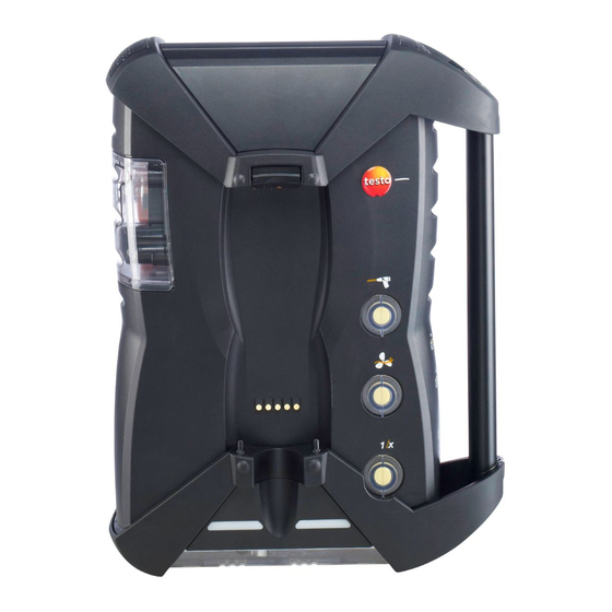
2 Product description 4 Guide groove for locking with meas. box 2.2. Meas. box 2.2.1. Overview 1 Condensate trap and condensate container 2 Locking/unlocking button for Control Unit 3 Particle filter 4 Filter fresh air inlet (option: fresh air valve / measurement range extension overall (5x)) 5 Contact bar for connection to Control Unit 6... -
Page 9: Status Display
2 Product description 2.2.2. Status display The status display shows the operating status of the meas. box: Display Status green / permanent (meas. box Mains operation or rech. batt switched on) operation / rech. batt. fully charged red / flashing (meas. box •... -
Page 10: Menu Guidance Meas. Box
10 Covering cap gas channel access (only for servicing purposes) Plugged in covering cap: Position ( ) must not be changed! 11 Pressure ports p+ and p- 12 Testo data bus 2.2.4. Menu guidance meas. box Main menu Menu Description... -
Page 11: Modular Flue Gas Probe
3 First steps Main menu Menu Description Sensor settings Make sensor settings, perform calibration / adjustment Programs Configure and activate measuring programs Instrument Error diagnosis Display of present errors diagnosis Gas path check Perform tightness test Sensor diagnosis Perform sensor diagnosis Device information Display of device information 2.2.5. -
Page 12: Meas. Box
±0...+35°C. If the rech. batt. had been completely discharged, the charging time at room temperature will take about 7h (charging with mains adapter) or approx. 14h (charging via Testo Data bus). Charging via meas. box ✓ Control Unit is locked to meas. box or is connected via the Testo Data bus cable. -
Page 13: Getting To Know The Product
Connecting via Data bus cable (accessory) The individual components (e.g. Control Unit with meas. box or meas. box with meas. box) can be connected using the Testo databus cable. > Connect the Data bus cable to the Data bus interfaces. - Page 14 Electrical termination of the bus system The databus system is linear in structure. The Control Unit or the Testo databus controller with USB connection represents the beginning of the line. The end is represented by the last components connected in the system (meas.
-
Page 15: Connection Via Bluetooth ® (Option)
3 First steps ® 3.2.2.3. Connection via Bluetooth (option) The Control Unit can be connected to a meas. box or a PC/ ® Notebook via Bluetooth , as long as both components are equipped with this function. 3.2.3. Switching on Before switching on >... -
Page 16: Printing / Saving Data
3 First steps - plugged to the mains cable of the meas. box, so that starting via ® Bluetooth is enabled. Switching on > press The Welcome Screen is displayed (approx. 5s) The Control Unit display screen appears. The Control Unit searches for connected meas. boxes and shows these as independent tabs in the display. -
Page 17: Folders / Locations
3 First steps 3.3. Folders / Locations (only available via Meas. Box tab) All readings can be saved under the currently active location. Readings not yet saved are lost when the measuring instrument is switched off. Folders and locations can be created, edited, copied and activated. Folders and locations (incl. - Page 18 3 First steps Parameter Description Pitot Tube The parameter "Pitot tube factor" influences the Factor measurement of flow speed, volume flow rate and mass flow. The Pitot factor depends on the type of Pitot tube used: Straight Pitot tubes: Factor = 0.67 Prandt’l Pitor tubes (bent): Factor = 1 Humidity The parameter "Humidity"...
-
Page 19: Using The Product
4 Using the product Parameter Description Dewpoint The parameter "Dewpoint" (combustion air dewpoint) influences the calculation of qA (flue gas loss) and flue gas dew point. The factory setting for the dewpoint is 1.5°C. To achieve a higher accuracy, the values can be adjusted to the actual ambient conditions. -
Page 20: Instrument Settings
4 Using the product ✓ A menu / function is opened in which the Options menu is displayed on the left function key. 1. P ress [Options]. 2. Select option: Depending on the menu / function from which the Options menu was opened, various functions are available. - Page 21 4 Using the product Display Measurement parameter Effg Efficiency under due consideration of the heat value range Carbon monoxide Carbon monoxide undiluted AmbCO Ambient carbon monoxide Nitrogen monoxide Nitrogen dioxide Nitrogen oxide Sulphur dioxide Hydrogen sulphide Hydrocarbon Hydrogen λ Air ratio Smoke numberØ...
-
Page 22: Date / Time
4 Using the product Change parameter / unit in a line: 1. Select the line: [▲], [▼] → [Change] 2. S elect the parameter: [▲], [▼] → [OK] 3. Select the unit: [▲], [▼] → [OK] 4. Save changes: [OK] Options: >... - Page 23 4 Using the product The program Flue Gas (before + after cat) checks whether the meas. box is equipped with a fresh air valve. If not, a measuring program with normal flue gas measurement will be added, instead of the program Flue Gas (before + after cat).
- Page 24 4 Using the product Parameter Function Start Determine the start criterion • The measuring program is started at any time (the function key automatically changes to the stop function). • Time Start of measurement at a pre-programmed time. • External signal Trigger signal to control the start of measuring programs.
-
Page 25: Measuring
4 Using the product 1. Select the program: → [OK]. 2. Press [Change]. 3. Press [Change]. 4. Edit program name: ], [◄], [►]. 5. Confirm the entry: [OK]. 6. Repeat steps 4 and 5 as required. 7. Press [Next]. 8. Perform steps 4 and 7 for further criteria accordingly. 9.... -
Page 26: Applications
4 Using the product > Activate the location to which the readings are to be assigned. > Make sure that the gas outlets are free, so that the gas can escape without obstruction. Otherwise the measurement results may be corrupted. 4.2.2. - Page 28 0971 3511 en 01 V01.00 en_GB...
Need help?
Do you have a question about the 350 and is the answer not in the manual?
Questions and answers